1
Installation
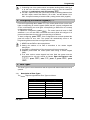
2.4.1.1
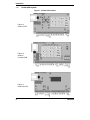
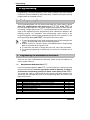
PCB Terminals and Fuses
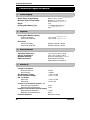
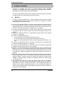
Terminal
AC (2)
BATTBATT+
S
D
C
B
A
L/S (2)
AUXAUX+
SW+
TAMP
Z1 - Z8
T
R
AUXAUX+
Description
Transformer AC in
Standby Battery negative
Standby Battery positive
SAB Strobe switched negative
SAB negative Supply
SAB negative Tamper return
SAB Bell switched negative
SAB positive Supply
Loudspeaker
Auxiliary Supply negative
Auxiliary Supply positive
Switched Positive output
Global Tamper loop
Zone loops
Keypad data
Keypad data
Auxiliary Supply negative
Auxiliary Supply positive
Note
NOT for mains supply
use for detectors
use for detectors
use for RKP(s)
use for RKP(s)
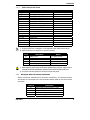
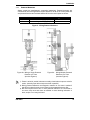
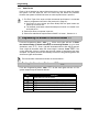
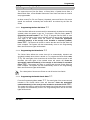
1) A spare mains fuse is supplied in a clip adjacent to the mains terminal block.
2) Spare PCB fuses are supplied in a press-seal bag.
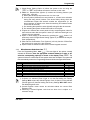
Fuse
F1
F2
F3
F4
F5
Description
Battery fuse
Bell & Strobe fuse
L/S & Detector Auxiliary fuse
RKP Auxiliary fuse
Power Supply Output fuse
Rating
F1A, 250V, 20mm
F1A, 250V, 20mm
F500mA, 250V, 20mm
F500mA, 250V, 20mm
F1.6A, 250V, 20mm
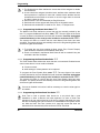
1) When replacing a fuse always observe the specified rating and type - failure to do so
is dangerous and will invalidate the warranty. Fuses should comply with IEC 127.
2) The press-seal bag must NOT be stored inside the panel.
2.4.2
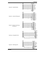
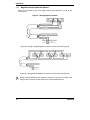
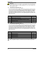
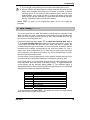
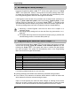
Wiring the External Sounder and Strobe
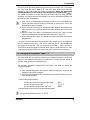
Always consult the manufacturer's connection instructions. The external sounder
and strobe are connected to the five terminals labelled SAB on the control panel
as follows:
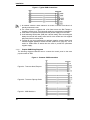
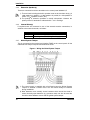
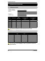
Terminal
A
B
C
D
S
INS 034-9
Description
Permanent Positive Supply (+12V)
Switched Negative to Activate Sounder
Negative Tamper Return
Permanent Negative Supply (0V)
Switched Negative to Activate Strobe
9