1
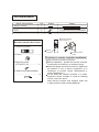
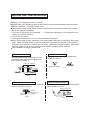
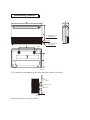
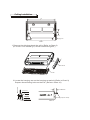
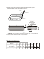
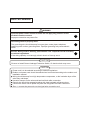
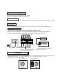
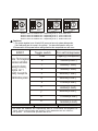
E-II-YDFC-0907
ENGLISH
INSTALLATION MANUAL
DIGITAL SCROLL SERIES
AIR-CONDITIONER CEILING AND FLOOR TYPE
Models:
YDFC-36C(A/B)15A
YDFC-45C(A/B)15A
YDFC-56C(A/B)15A
YDFC-71C(A/B)15A
YDFC-80C(A/B)15A
YDFC-90C(A/B)15A
YDFC-112C(A/B)15A
YDFC-140C(A/B)15A
For correct installation, read this manual before starting installation.
Only trained and qualified service personnel should install, repair or service air conditioning equipment. Users
should not install the air conditioner by themselves.
All pictures are only sketches. If there is any difference between pictures in this manual and the actual shape
of the air conditioner you purchased, the actual shape shall prevail.
INSTALLATION PRECAUTION
To install properly, please read this manual at first.
The air conditioner must be installed by qualified persons.
When installing the indoor unit or its tubing, please follow this manual as strictly as possible.
When all the installation work is finished, please turn on the power only after a thorough
check.
No further announcement if there is any change of this manual caused by product improvement.
Note: The installor should illustrate to users how to correctly use and maintain the air-conditioner, as well as remind users to carefully read and keep both Installation Manual and
Owner's Manual well.
INSTALLATION PLACE
The Indoor Unit
There is enough room for installation and maintenance.
The ceiling is horizontal, and its structure can endure the weight of the indoor unit.
The air outlet and the air inlet are not impeded, and the influence of external air is the least.
The air flow can reach throughout the room.
The connecting pipe and drainpipe could be extracted out easily.
There is no direct radiation from heaters
Cautions
Location in the following places may cause malfunction of the machine. (If unavoidable,
please consult your local dealer.)
a. There exists petrolatum.
b. There is salty air surrounding(near the coast).
c. There is caustic gas(the sulfide, for example) existing in the air (near a hot spring).
d. The Volt vibrates violently(in the factories).
e. In buses or cabinets.
f. In kitchen where it is full of oil gas.
g. There is strong electromagnetic wave existing.
h. There are inflammable materials or gas.
i. There is acid or alkaline liquid evaporating.
j. Other special conditions.
Notes Before Installation
1. Select the correct carry-in path.
2. Move this unit as originally packaged as possible.
3. If the air conditioner is installed on a metal part of the building, it must be electrically
insulated according to the relevant standards to electrical appliances.
NOTE:
Remark per EMC Directive 89/336/EEC
For to prevent flicker impressions during the start of the compressor (technical process),
following installation conditions apply.
1. The power connection for the air conditioner has to be done at the main power distribution.
The distribution has to be of a low impedance, normally the required impedance reaches
at a 32A fusing point.
2. No other equipment has to be connected with this power line.
3. For detailed installation acceptance, please refer to your contract with the power supplier
if restrictions do apply for products like washing machines, air conditioners or electrical
ovens.
4. For power details of the air conditioner, refer to the rating plate of the product.
5. For any question contact your local dealer.
ACCESSORIES
Name of Accessories
Owner's manual
Installation manual
Hook
Hanging arm
Q'ty
1
1
2
2
Qutline
Usage
(This manual)
For wall mounting installation
For ceiling installation
3 Mounting screw B
ST2.9x10-C-H
Remote controller & Its Frame
1. Remote controller..................1
1 Remote
controller
2. Frame...................................1
2 Remote controller
holder
Cautions on remote controller installation
3. Mounting screw
(ST2.9x10-C-H).....................2
4. Alkaline dry batteries(AM4)
...............................................2
Never throw or beat the controller.
Before installation, operate the remote controller
to determine its location in a reception range.
Keep the remote controller at least 1m apart from
the nearest TV set or stereo equipment. (It is
necessary to prevent image disturbances or
noise interferences.)
Do not install the remote controller in a place
exposed to direct sunlight or close to a heating
source, such as a stove.
Note that the positive and negative poles are
in right positions when loading batteries.
INDOOR UNIT INSTALLATION
Installing 10 hanging screw bolts. (4 bolts)
Please refer to the following figure for the distance measurement between the screw bolts.
Please install with 10 hanging screw bolts.
The handling to the ceiling varies from the constructions, consult the construction personnels for the specific procedures.
1. The size of the ceiling to be handled ... ... do keep the ceiling flat. Consolidate the roof
beam for possible vibration.
2. Cut off the roof beam.
3. Strengthen the place cut off, and consolidate the roof beam.
Carry out the pipe and line operation in the ceiling after finishing the installation of the main
body. While choosing where to start the operation, determine the direction of the pipes to
be drawn out. Especially in case there is a ceiling, position the refrigerant pipes, drain pipes,
indoor & outdoor lines to the connection places before hanging up the machine.
The installation of hanging screw bolts.
New concrete bricks
Wooden construction
Put the square timber traversely over the
roof beam, then install the hanging screw
bolts. (Refer to Chart 1)
Inlaying or embedding the screw bolts.
(Refer to Chart 2)
Timber over the beam
(Slide insertion)
(Blade shape insertion)
Chart 2
Roof beam
Ceiling
Hanging screw bolts
Chart 1
For Original concrete bricks
Use embedding screw bold, crock and stick
harness. (Refer to Chart 3)
Steel roof beam structre
Install and use directly the supporting angle
steel. (Refer to chart 4)
Hanging screw bolt
Steel bar
Embedding screw bolt
(Pipe hanging and embedding
screw bolt)
Chart 3
Supporting
angle steel
Hanging bolts
Chart 4
Wall Mounting Installtion
D. Connecting point of
refrigerant pipe
(D. gas side)
Drain point
E. Connecting point of
refrigerant pipe
(E. Liquid side)
Hook
Chart 5
1.Fix the hook with tapping screw onto the wall.(Refer to Chart 6)
Hook
Tapping screw
Washer
<6mm
Chart 6
2.Hang the indoor unit on the hook.
Ceiling Installation
Hanging arm
Chart 7
1.Remove the side board and the grille.(Refer to Chart 8)
(For models 11200-14000W type, do not remove the grille.)
Side board
Grille
8
13mm
Screw nut
20
25mm
2.Locate the hanging arm on the hanging screw bolt.(Refer to Chart 9)
Prepare the mounting bolts on the unit.( Refer to Chart 10)
Washer
Hanging
screw bolt
Mounting bolt(max.40mm)
Hanging arm
Chart 9
Chart 10
3.Hang the unit on the hanging arm by sliding backward. Securely tighten
the mounting bolts on both sides.(Refer to Chart 11)
Hanging
screw bolt
Hanging arm
Mounting bolt
D. Connecting point of
refrigerant pipe
(D.gas side)
E. Connecting point of
refrigerant pipe
(E. Liquid side)
Drain point
Chart 11
ATTENTION: The figures above are based on model with 3600-7100W type as rated
capacity, which may differ from the unit you purchased.
The dimension of the unit
Capacity(W)
A
B
C
D
E
F
G
H
3600-7100W type
990
660
206
505
506
907
200
203
8000-9000W type
1280
660
206
795
506
1195
200
203
11200-14000W type
1670
680
244
1070
450
1542
200
240
INSTALL THE CONNECTING PIPE
Do not let air, dust, or other impurities fall in the pipe system during the time of installation.
The connecting pipe should not be installed until the indoor and outdoor units have been
fixed already.
Keep the connecting pipe dry, and do not let moisture in during installation.
The Procedure of Connecting Pipes
1. Measure the necessary length of the connecting pipe, and make it by the following way.
1) Connect the indoor unit at first, then the outdoor unit.
,
Bend the tubing in proper way. Don t harm them.
Cautions
Daub the surfaces of the flare pipe and the joint nuts with frozen oil, and wrench it for 3~4
rounds with hands before fasten the flare nuts. (Refer to chart 12)
Be sure to use two wrenches simultaneously when you connect or disconnect the pipes.
2) The stop valve of the outdoor unit should be closed absolutely (as original state). Every
time you connect it, first loosen the nuts at the part of stop valve, then connect the flare
pipe immediately (in 5 minutes). If the nuts have been loosened for a long time, dusts
and other impurities may enter the pipe system and may cause malfunction later. So
please expel the air out of the pipe with refrigerant before connection.
3) Expel the air (refer to the Expel The Air ) after connecting the refrigerant pipe with the
indoor unit and the outdoor unit.
Then fasten the nuts at the repair-points.
Notices For Benable pipe.
o
The bending angle should not exceed 90 C
Bending position is preferably in the bendable pipe. The larger the better it is .
Do not bend the pipe more than three times.
Bend the connecting pipe of small wall thickness.
Cut out a desired concave at the bending part of the insulating pipe.
Then expose the pipe(cover it with tapes after bending).
To prevent collapsing of deforming, please bend the pipe at its biggest radius.
Use bender to get a small radius pipes.
Use the market brass pipe.
Be sure to use the same insulating materials when you buy the brass pipe. (More than
9mm thick)
Use frozen oil
Bend the pipe with thumb
Make the ends
straight
Min-radius 100mm
Chart 12
Chart 13
Chart 14
2. Locate The Pipe
1) Drill a hole in the wall (suitable just for the size of the wall conduit, 90mm in general), then
set on the fittings such as the wall conduit and its cover.
2) Bind the connecting pipe and the cables together tightly with binding tapes. Do not let air
in, which will cause water leakage by condensation.
3) Pass the bound connecting pipe through the wall conduit from outside. Be careful of the
pipe allocation to do no damage to the tubing.
3. Connect the pipes.
4. Then, open the stem of stop valves of the outdoor unit to make the refrigerant pipe connecting the indoor unit with the outdoor unit fluently flow.
5. Be sure of no leakage by checking it with leak detector or soap water.
6. Cover the joint of the connecting pipe to the indoor unit with the soundproof/insulating
sheath (fittings), and bind it well with the tapes to prevent leakage.
SIZES OF THE PIPES
R22/R407C
R410A
R410A
19
12.7
15.9
Liquid
9.53
6.35
9.53
Models
All
36
45-140
Gas
CONNECT THE DRAIN PIPE
1. Install indoor unit drain pipe
The outlet has PTI screw bread, Please use sealing materials and pipe sheath (fitting)
when connecting PVC pipes.
CAUTIONS
The drain pipe of indoor unit must be heat insulated, or it will condense dew, as well as
the connections of the indoor unit.
Hard PVC binder must be used for pipe connection, and make sure there is no leakage.
With the connection part to the indoor unit, please be noted not to impose pressure on the
side of indoor unit pipes.
When the declivity of the drain pipe downwards is over 1/100, there should not be any win
ding.
The total length of the drain pipe when pulled out traversely shall not exceed 20m, when
the pipe is over long, a prop stand must be installed to prevent winding.
Refer to the figures on the right for the installation of the pipes.
Put as deep as possible
(about 10cm)
1.5m~2m
Bend
S shape
Insulating Downward declivity
material lower than 1/100
Downward declivity
lower than 1/100
2. Drainage test
Check whether the drainpipe is unhindered
New built house should have this test done before paving the ceiling.
VP30
ELECTRIC WIRING
!
WARNING
Specified power cables should be used. Do not apply any pressure on the
terminals used to connect.
Improper connection may cause fire.
Grounding must be properly done.
The grounding wire should be away from gas pipes, water pipes, telephone,
lightening rods or other grounding wires. Improper grounding may cause electric
shock.
Electric Wiring must be done by professionals. Use a separate circuit according
to national regulations.
If the wiring capacity is not enough, electric shock or fire may occur.
CAUTION
Be sure to Install Current Leakage Protection Switch, Or electric shock may occur.
CAUTION
Power cord is to be selected according to national regulations.
Outdoor unit power cord should be selected and connected according to the outdoor unit
installation manual.
Wiring should be away from high temperature components, or the insulation layer of the
wires may melt down.
Use wire clamp to fix the wires and terminal block after connection.
Control wire should be wrapped together with heat insulated refrigerant pipes.
Connect the indoor unit to power only after the refrigerant has been vacuumed.
Don t connect the power wire to the signal wire connection end.
The Specification of Power
2200-14000W type
TYPE(W)
POWER
PHASE
1-PHASE
FREQUENCY AND VOLT
220~ 50Hz/60Hz
CIRCUIT BREAKER/FUSE
(A)
5/3
2
2.0
INDOOR UNIT POWER WIRING(mm )
2
INDOOR/OUTDOOR GROUND WIRING (mm )
CONNECTING 2
WEAK ELECTRIC
WIRING ( mm ) SIGNAL
2.0
1.0
Table 3
Caution:
A disconnection device having an air gap contact separation in all active conductors should
be incorporated in the fixed wiring according to the National Wiring Regulation.
Wiring Chart
Power
220
50Hz/60Hz
INDOOR UNIT
CENTRAL CONTROL
MONITOR(CCM)
COMPUTER
INDOOR UNIT
OUTDOOR UNIT
INDOOR UNIT
the shielded twisted-pair wire
Caution:
The reserved function is indicated in broken line table,users can select it when necessary
Indoor/Outdoor Unit Signal Wire
Connect the wire according to their numbers.
Wrong connection may cause malfunction .
Wiring Connection
Seal the wiring connection with the insulation material , or the condensing dew will be caused.
Panel Wiring
Connect the Swing Motor terminal block according to the Panel Installation Manual.
Terminal Board Diagram
Please refer to the indoor unit wiring diagram for the wiring.
Note: The air-conditioners can connect with Central Control Monitor (CCM). Before operation,
please wiring correctly and set system address and network address of indoor units.
Single phase indoor unit
ON
X
Y (E)
P
Q
1
2
SW1
TO INDOOR POWER To Central Control
Monitor(CCM)COMM. BUS
220V 50Hz/60Hz
TO OUTDOOR
COMM. BUS
To wire controller
The reserved wire control function is indicated
in broken line table,users can purchase the
wire controller when necessary
Please adopt the shielded twisted-pair wire,
and connect the shielded layer to (E)
CONTROL
Please number the indoor units during the installation . For example, for the first outdoor unit ,the number
of the first indoor unit is 1-1, the second indoor unit is 1-2, and the set address is 1 and 2
respectively , the others is analogical.
System address code
POWER_S
NUM_S
CD
01
AB
CD
AB
8
67 9
ENC1
EF
2345
2345
0
EF 1
8
67 9
Hoursepower code
ENC2
NUM_S
AB
1
ENC2
1
2
SW1
ENC2
Model 3
8
67 9
Model 2
the
the
the
the
CD
CD
CD
AB
AB
8
67 9
2
SW1
Model 1
Model 1 show
Model 2 show
Model 3 show
Model 4 show
8
67 9
1
ENC2
EF 01
2345
2
2345
CD
EF 01
2345
1
SW1
NUM_S
ON
EF 01
address `0-F` respectively, that
address `0-F` respectively, that
address `0-F` respectively, that
address `0-F` respectively, that
2345
EF 01
NUM_S
ON
AB
ON
8
67 9
NUM_S
ON
2
SW1
ENC2
Model 4
is, `0-15` indoor unit;
is, `16-31` indoor unit;
is, `32-47` indoor unit;
is, `48-63` indoor unit.
Cautions:
1.The system together have 64units(0-63),everyone has only system addresscode,
If two addresses are the same in one system , the abnormal operation will occur.
2.Please switch off the power before setting,otherwise the unexpected error will occur.
ENC1
Note: The horsepower
has been set before
leaving the factory ,
anyone can t
modify it except the
maintenance person.
ENC2
Toggle switch
For set horsepower
Code
Capacity(Horsepower)
0
2200W(0.8HP)
1
2800W(1.0HP)
2
3600W(1.2HP)
3
4500W(1.5HP)
4
5600W(2.0HP)
5
7100W(2.5HP)
6
8000W(3.0HP)
7
9000W(3.2HP)
8
11200W(4.0HP)
9
14000W(5.0HP)
TOGGLE SWITCH
FOR SETTING ADDRESS
'0-F' show the address '0-F' respectively, that is, '0-15' indoor unit (together 16
units), and the others follow the analogy. If two addresses are the same in
one system , the abnormal operation will occur.
DE - COMMISSIONING DISMANTLING & DISPOSAL
This product contains refrigerant under pressure, rotating parts, and electrical connections which
may be a danger and cause injury!
All work must only be carried out by competent persons using suitable protective clothing and safety precautions.
Read the Manual
Risk of electric shock
Unit is remotely controlled
and may start without warning
1. Isolate all sources of electrical supply to the unit including any control system supplies switched by the unit. Ensure that all points of electrical and gas
isolation are secured in the OFF position. The supply cables and gas pipework may then be disconnected and removed. For points of connection refer
to unit installation instructions.
2. Remove all refrigerant from each system of the unit into a suitable container using a refrigerant reclaim or recovery unit. This refrigerant may then be
re-used, if appropriate, or returned to the manufacturer for disposal.Under No circumstances should refrigerant be vented to atmosphere. Where
appropriate, drain the refrigerant oil from each system into a suitable container and dispose of according to local laws and regulations governing
disposal of oily wastes.
3. Packaged unit can generally be removed in one piece after disconnection as above. Any fixing down bolts should be removed and then unit lifted from
position using the points provided and equipment of adequate lifting capacity. Reference MUST be made to the unit installation instructions for unit
weight and correct methods of lifting. Note that any residual or spilt refrigerant oil should be mopped up and disposed of as described above.
4. After removal from position the unit parts may be disposed of according to local laws and regulations.
E-II-YDFC-0907
ENGLISH