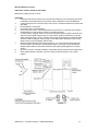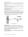
1
Installation Manual
for the
D3001 / D3011 / D3021 / D3022
EN Compliant CIE
CIE = v5 Software or later,
ACE = v2 Software or later
These products are suitable for use in systems designed to comply with PD6662:2004 and
EN50131-1:
D3001 = Grade 3, Environmental Class II
D3011 = Grade 3, Environmental Class II
D3021 = Grade 2, Environmental Class II
D3022 = Grade 3, Environmental Class II
Dycon Ltd
Tel: +44 (0)1443 471060 - Fax: +44 (0)1443 479374
www.dyconsecurity.com - [email protected]
INDEX
Introduction
System Architecture
Part Numbers and Pictures
3
4
6
What to Do: READ THIS
System Planning and Design
Site Survey
Installation
System Testing
Factory Defaults and Resetting
Help Desk
Frequently Asked Questions
9
11
12
13
14
14
15
The Details:
Control Panels D3001, 3011, 3021, D3022
Proximity Readers D3232
Keypads D3202-B, D3205, D3211-B, D3212-B
ADD8 D3300
ADD8PSU D3500, D3510
ADD-R D3301
Plug-on GSM Radio Modem D2070
Plug-on Output Board D3024
Plug-on Audio Module D3025
Wire-free Detectors D4809, D4810, D4811, D4812, D4814, D4815, D4820
18
28
30
36
39
44
48
51
52
53
Telephone Line Connections
PSTN Digi-Modem
Analogue Telephone Line Connection Options
PABX
ISDN, ISDN2, ISDN30, Home Highway, Business Highway
ADSL, ‘Broadband’
The ‘Call Minder’ call answering service
Safety Earth connection
66
66
67
69
70
72
74
74
System Bus Wiring
Audio Bus Wiring
Wired Zone Inputs
Wired Tamper Inputs
Internal Sounders
Siren/Bell and Strobe Connections
Programmable Outputs
Power Supplies and Batteries
Auxiliary Power Outputs
75
81
82
84
85
86
88
89
93
Appendix 1 Aerial Siting for GSM Radio Networks
Appendix 2 Wire-free Detectors, ADD-R, Siting, Range, Aerial Options
Appendix 3 Current Consumption of all Units
Appendix 4 Setting-up a Basic System (Panel + 1 Keypad)
Appendix 5 Specification and Regulations
Appendix 6 Approvals
Appendix 7 Glossary of Terms
94
96
101
102
104
105
106
D3000 Series – Installation Manual – D3000‐INST/09H/v3 ‐ 2 Introduction
The D3001/11/21/22 control systems are designed to suit small to large size intruder alarm
installations (8 to 208 detectors). Extensive hardware and programmable options make these systems
suitable for the national requirements of many countries and for installations to European Standard
EN50131-1 Grade 2 and 3.
Systems are fully adaptable to meet all initial design specifications. Future expansion and additions
may be made to meet changing requirements in the easiest manner imaginable, i.e. any zone input
on any unit (panel, ADD8, keypad, ADD8PSU or ADD-R) may be programmed as a zone, a tamper, a
24 hour circuit, a PA, an Exit Terminate button etc. in any order and in any group. Equally, any
programmable output on any unit may be programmed to any of the 70+ output type options. See
page 5 for tables of product features.
All control panels have fully supervised loop (FSL) Zone inputs. All control panels have fully
programmable outputs in addition to the normal bell and strobe output plus a sounder output for
internal sounders.
Full ‘dual-path’ alarm reporting (PSTN and radio) is available with a built-in (PSTN) Digi-Modem for
telephone lines and plug-on options for a VDN (Vodafone Data Network) or GSM (Global System for
Mobile Communications) radio modem. Plug-on interface options allow for connection to other
communication systems.
The network (4 core bus) wiring provides system expansion via keypads, ADD8s, ADD8PSUs and
ADD-Rs.
Low-cost and multimedia keypads are available. The multimedia version has 4 FSL inputs, 2
programmable outputs, a sounder output and audio functions for a user help, hands-free 2-way
speech system. A proximity tag reader is also available to allow the system to be set and unset from
outside the protected premises.
ADD8s have 8 FSL inputs, 4 programmable outputs and a sounder output plus a socket where an
engineer’s keypad may be plugged-in. ADD8PSUs have the same facilities as an ADD8 plus they
include a fully monitored 3 Amp power supply, backup batteries and bell/siren and strobe outputs.
The ADD-R allows any of the Dycon range of 868 MHz wire-free detectors to be used with the control
panels. More than one ADD-R can be added to a system to provide coverage on large sites.
The D3001/11 systems when fully expanded have 144 FSL wired inputs, 64 wireless inputs, 13
siren/bell outputs (SAB/SCB), 13 strobe outputs, 72 programmable outputs (25 relay, 47 transistor)
and 23 internal sounder outputs for 16 ohm speakers. The D3021 system when fully expanded has
36 FSL wired inputs, 16 wireless inputs, 1 siren/bell output (SAB/SCB), 1 strobe output, 15
programmable outputs (1 relay, 14 transistor) and 6 internal sounder outputs for 16 ohm speakers.
The D3021 system when fully expanded has 52 FSL wired inputs, 1 siren/bell output (SAB/SCB), 1
strobe output, 25 programmable outputs (1 relay, 24 transistor) and 8 internal sounder outputs for 16
ohm speakers. The D3001/11 control panel and ADD8PSUs incorporate a 3 Amp Switched Mode
power supply with integral current sensing and measurement, temperature compensation, battery
condition testing plus reverse and deep-discharge protection. Two case sizes are available for the
control panel. The D3001 can accommodate two 7Ah batteries. The D3011 has space for up to two
17Ah batteries or four 7Ah batteries. The D3021 and D3022 incorporate a 1.2 Amp Switched Mode
power supply and the case has space for two 7Ah batteries.
All control panels include a serial port for connection to a printer (temporary or permanent).
An optional engineer’s keypad may be plugged into the control panel or ADD or ADD8PSU or ADD-R
throughout the system. All control panels may be programmed using any keypad or an engineer’s
keypad.
Remote programming (downloading) is supported via multiple transmission paths. The D3054
programmer is software that runs on a PC and may be connected to the control panel via PSTN, VDN
or GSM. In addition the programming PC (or laptop) can be connected by a serial lead directly to the
control panel.
D3000 Series – Installation Manual – D3000‐INST/09H/v3 ‐ 3 System architecture
All control panels may be set for commercial or domestic use. All systems may be programmed in
the same manner. All engineering programming at the keypads is accessed by menus. Any menu
may be selected by a ‘short cut’ code of one letter and 2 numbers. Copy and paste functions allow
many zones, groups and outputs to be selected and programmed in a short time. Refer to the table
on the next page for details of each system’s expansion options.
The D3001/11 Control Panels
The D3001/11 has up to 208 zone inputs. Each is associated with 1 of up to 20 groups. Groups may
be set and unset using operator codes and/or proximity tags/cards. There are up to 68 operator codes
and prox tags (these incorporate users and engineers). Each operator code can be associated with
any or all of the 20 groups. Fast setting and unsetting of a particular selection of groups is possible for
each of the operator codes. Operator codes can have different attributes for use as managers, users,
cleaners etc…
Each keypad can be associated with any or all of the 20 groups. Each group has its own bell timers
which control the operation of the bell(s) for that group. These timers are used by the group when the
system is not full set. When the system is full set (when each group that is required to be set for
‘system full set’ has been set), then the entire system can use the global bell timers to control the
bell(s).
When set to commercial mode, the D3001/11 is an independent group setting control panel. There
are 20 groups that may be independently set and unset. Each of the 208 zones can only be
associated with one group, i.e. groups cannot overlap. There are no Vari-Zones. Keypads can be
associated with groups. Bell/siren and strobe outputs may be associated with each group. Four ‘Quick
Set’ keys on each keypad allow several groups to be set and unset together.
When set to domestic mode, the D3001/11 is a part setting control panel. There are 4 groups.
Groups cannot overlap. Only one group may be set at any time. Any or all of the 208 zone inputs may
be configured as a Vari-Zone. A Vari-Zone belongs to each of the 4 groups and can have a different
action in each group.
The D3021/22 Control Panel
The D3021 and D3022 have up to 52 zone inputs. Each is associated with 1 of up to 4 groups.
Groups may be set and unset using operator codes and/or proximity tags/cards. There are up to 22
operator codes and prox tags (incorporating user and engineers). Each operator code can be
associated with any or all of the 4 groups. Fast setting and unsetting of a particular selection of
groups is possible for each of the 22 operator codes. Operator codes can have different attributes for
use as managers, users, cleaners etc…
When set to commercial mode, the D3021/22 are independent group setting control panels. There
are 4 groups that may be independently set and unset. Each of its zones can only be associated with
one group, i.e. groups cannot overlap. There are no Vari-Zones. Keypads can be associated with
groups. Bell/siren and strobe outputs may be associated with each group. Four ‘Quick Set’ keys each
allow each group to be set and unset.
When set to domestic mode, the D3021/22 are part setting control panels. There are 4 groups.
Groups cannot overlap. Part set is where one or more of the 4 groups is not set when the control
panel is set. Any or all of the 48 zone inputs may be configured as a Vari-Zone. A Vari-Zone belongs
to each of the 4 groups and can have a different action in each group.
D3000 Series – Installation Manual – D3000‐INST/09H/v3 ‐ 4 D3000 Series – Installation Manual – D3000‐INST/09H/v3 ‐ 5 Part Numbers
D3001
D3011
D3021
D3022
216 zone control panel - Case size = 2 x 7Ah batteries
216 zone control panel - Case size = 2 x 17Ah batteries or 4 x 7Ah batteries
52 zone control panel - Case size = 2 x 7Ah batteries
52 zone control panel - Case size = 2 x 7Ah batteries
D2070
D3024
D3025
GSM radio modem A panel plug-on accessory
Output board A panel plug-on accessory
Audio board A panel plug-on accessory
D3202-B
D3211-B
D3212-B
D3205
Multimedia keypad - As D3201 multimedia keypad + card/tag prox reader
Lo-Cost keypad - Keypad (no i/p, no o/p, no sounder o/p, no audio)
Lo-Cost keypad - As D3211 keypad + card/tag prox reader
Engineers Keypad - As D3202 multimedia keypad + plug-in connection and cased
D3232
D3233
D3240
Proximity reader - Card/tag prox reader (external reader IP sealed)
Proximity reader sensor - Additional sensor for use with D3232. IP sealed.
Proximity tag – Key fob style for use with D3202, D3212 and D3232.
D3300
D3301
ADD8 - 8 FSL wired zone inputs + 4 programmable outputs + sounder o/p
ADD-R receiver - 868MHz. for wire-free detectors (no outputs)
D3500
ADD8PSU - As ADD8 + 3amp power supply
Case size = 2 x 7Ah batteries
ADD8PSU - As ADD8 + 3amp power supply
Case size = 2 x 17Ah batteries or 4 x 7Ah batteries
D3510
D4809
D4810
D4811
D4812
D4814
D4815
D4830
D4831
D4832
Wire-free pet tolerant PIR - 868MHz. Use with ADD-R
Wire-free PIR - 868MHz. Use with ADD-R
Wire-free door contact - 868MHz. Use with ADD-R
Hand-held controller - 868MHz. Use with ADD-R
Smoke detector - 868MHz. Use with ADD-R
Water detector - 868MHz. Use with ADD-R
Quarter-wave aerial - Supplied with ADD-R
Dipole aerial - Optional aerial for use with ADD-R
Yagi aerial - Optional aerial for use with ADD-R
D3054
D0730
Programming Software - Programmer for up/downloading and local connection
Security ADSL filter - For connection to ADSL (Broadband) PSTN telephone lines
D3000 Series – Installation Manual – D3000‐INST/09H/v3 ‐ 6 D3000 Series – Installation Manual – D3000‐INST/09H/v3 ‐ 7 D3000 Series – Installation Manual – D3000‐INST/09H/v3 ‐ 8 System Planning and Design
Groups and Quick Set Keys
Although most items can be programmed in any order and at any time during installation or at a later
time, it is important to program some items before others. This is essential when programming group
features and the operation of the Quick Set keys.
Program these items in this order:
1. Planning
Plan the operation of the alarm system and decide how many groups are required and how they will
be used. Refer to System Description and Architecture on pages 3 and 4. Decide the location and
wiring routes for all keypads, ADD8 / ADD8PSUs, ADD-Rs and the control panel with its radio and
telephone modems.
2. The System Type
Select domestic or commercial Mode. Refer to System Architecture on page 4 and menu C01 in the
Programming Manual.
3. Zones
Select one or more zones and associate them with the groups required. A group will be ‘unused’ if no
zones have been associated with it. Ensure that all of the planned groups have one or more zones
associated with them. For each used zone, select that zone’s attributes, e.g. Entry/Exit Door, 24
Hour.
Zone names and other features can be programmed later but we recommend that you do it now to
avoid confusion. Refer to menus C10 to C14 in the Programming Manual.
4. Groups
Select the exit mode and attributes for each of the groups. A group will be ‘unused’ and cannot be
programmed if no zones have been associated with it.
Group names, timers and other features can be programmed later but we recommend that you do it
now to avoid confusion. Refer to menus D60 to D62 in the Programming Manual.
5. Quick Set Keys
Decide how the Quick Set keys are to be used and associate one or more groups to them.
A group will be ‘unused’ and cannot be associated if no zones have been associated with it.
Refer to menu D82 in the Programming Manual.
Operational Considerations
UserGroup
The D3001 and D3011 control panels can support up to 20 groups, and each operator may be given
access to any or all of these groups. This selection is called the UserGroup. An operator can only set
and unset groups that are in their UserGroup. See KeypadGroups and Quick Set keys below for
additional information.
AutoGroups
Each operator is allocated an AutoGroup which can be any or all of the groups in that Operator’s
UserGroup.
AutoGroups are operated without having to use the set / unset menu. The group(s) in that operator’s
AutoGroup will be set and unset when that operator code is entered and the OK key is pressed, e.g.
1 2 3 4 OK. See KeypadGroups and Quick Set keys below for additional information.
Operator Set/Unset Menu
Each operator Code has a ‘Menu 1 Access’ attribute. If this is enabled then that operator can
individually set and unset each of the groups in their UserGroup. These groups are set and unset
when the operator code is entered and the MENU key is pressed, e.g. 1 2 3 4 MENU. See
KeypadGroups below for additional information.
D3000 Series – Installation Manual – D3000‐INST/09H/v3 ‐ 9 System Planning and Design (cont’d)
Operator Set/Unset Menu (cont’d)
When setting via Menu 1, the display indicates whether each group is set or unset.
S = the group is set. U = the group is unset.
When the operator presses a NUMBER key, the status for the relevant group changes between set
and unset and vice versa. When the new status is selected the operator presses the OK key.
Keypad Groups
The D3001 and D3011 control panels can support up to 20 groups, and each keypad or proximity
reader may be given access to any or all of these groups. This selection is called the KeypadGroup.
An operator has control of all of the groups in their UserGroup at any keypad that has the same
groups in its KeypadGroup. Where the KeypadGroup is different from that operator’s UserGroup,
then only those groups that are in both the KeypadGroup and the UserGroup may be set and unset
from that keypad e.g. an operator’s UserGroup = 1,2,5,6,7 and 8. A KeypadGroup = 3,5,6,7,8 and 14.
The operator cannot set and unset groups 1 and 2 from that keypad.
Quick Set Keys
Each Quick Set key (A, B, C or D) can be associated with any combination of the groups on the
system.
Quick Set keys are a system function. Any operator can use any Quick Set key at any keypad.
The group(s) associated with a particular Quick Set key is the same whichever keypad is used. The
group(s) associated with a Quick Set key do not have to be the same as that keypad’s
KeypadGroup.
If an operator tries to set the system via a Quick Set key that is associated with group(s) that are not
in that operator’s UserGroup, then the Quick Set action will be completely ignored and the display will
read "Function Not Allowed".
Alarm Reporting
These control panels will not transmit alarms via PSTN nor VDN/GSM when the system is part-set.
Where alarm reporting to the ARC is required when one or more groups are unset, ensure that the
"Always Full Set" attribute is enabled in one or more group.
D3000 Series – Installation Manual – D3000‐INST/09H/v3 ‐ 10 Site Survey
It is strongly recommend that a site survey is conducted prior to installation of an alarm
system. This is to confirm that correct and sufficient equipment is available and that the
equipment is placed in the optimum position for its best performance.
1. VDN or GSM Radio Coverage
Firstly (and most important). all control panels can support dual signalling features. Where radio
communications will be used with your alarm system (VDN or GSM), select the position for the aerial.
This will be at the point of strongest signal ensuring that it is within the protected area. This is usually
the highest point in the building and well away from metal roofs, metal walls and sources of radio
interference. Refer to sections for Plug-on VDN or GSM Radio Modem and Appendix 1.
Call a help desk and ask for a radio signal strength prediction. See page 14. For this you will need to
know which radio network will be used and have the postcode of the site available. This will tell you if
there is radio coverage at the proposed site and the signal strength that can be expected. If there is
no radio coverage at the proposed site, the radio alarm reporting path using that radio network will
not operate. Another radio network may provide better signal strength.
Ensure that the aerial lead will be long enough to reach to the control panel. The control panel can be
mounted anywhere within the protected premises apart from the entry route.
Remember, it is always easier to find the point of strongest signal for the aerial before the equipment
is fitted to a wall. Moving aerials, cables, trunking etc… after installation is wasted time and effort.
2. PSTN Telephone line
Where telephone line communications will be used with your alarm system as part of the dual
signalling, select a suitable network termination point. If one requires fitting, request a telephone
network provider to install a line and termination at that point. Refer to page 71.
3. Wire-free Detectors
Determine the location of wire-free detectors. With a test transmitter and test receiver (ADD-R or
D4220) confirm that the quantity and proposed location(s) of receiver(s) will be sufficient to provide a
good signal strength from all detectors. On larger sites, more than one ADD-R receiver may be
required to provide that a good strength radio signal is received from all of the detectors. The D3001
and D3011 control panels can have up to 8 ADD-Rs connected on the bus line (64 total detectors per
Control Panel). The D3021 control panel can have up to 2 ADD-Rs connected (16 total detectors per
Control Panel). Refer to Appendix 3.
Where handheld PA transmitters will be used, ensure that the quantity and proposed location(s) of
ADD-R receivers is sufficient to provide good signal strength from all locations on the site. Refer to
Appendix 3.
4. Power and Battery Requirement
Very important. Estimate the power requirements of all alarm equipment, detectors and sounders
(both internal and external). Calculate voltage drops along cables. Ensure that sufficient cable is
available to keep the voltage drops within specifications and/or estimate the number of additional
ADD8PSU power supplies that will be required. See pages 79 to 85, pages 94 to 97 and Appendix 4.
5. Equipment Required
Confirm the number required, and locations of keypads, proximity readers, ADD8s, ADD8PSUs, ADDRs and wireless detectors.
6. Space Available
Ensure that there is sufficient space to mount the control panel.
7. Mains Supply
Ensure that there is a suitable mains fused spur connection point for the supply of mains power to the
control panel. If one requires fitting, contact a qualified electrician.
D3000 Series – Installation Manual – D3000‐INST/09H/v3 ‐ 11 Installation
1.
If you are new to the D3000 Series, see Appendix 5. This describes a basic installation
using a D3001 control panel and keypad. This is ideal for learning about the basic features in
these products.
2.
Ensure that a site survey has been done. This will locate the optimum positions for the
control panel, ADDs, radio aerials etc… This is important. If this has not been done, do it
now. See page 11. All D3000 Series systems are fully programmable. Any input or any
output on any component of the system may be programmed as required.
3.
Install bus wiring within the protected premises to meet the requirements of the site survey’s
measurements and calculations. See page 79 to 85. Refer also to Appendix 4.
4.
Remove the circuit board from the control panel case. Mark and drill the wall. Mount the case
on the wall. The case and batteries can weigh up to 20 kilogrammes. Select suitable
mountings. For heavier cases, Rawl plugs and 1.5 inch No10 screws are recommended.
Replace the circuit board. See pages 18 to 27.
5.
Route all cables, mains power, radio aerial lead, and telephone line into the case.
6.
Remove the fuse from the mains fused terminal block and connect the mains supply cable.
Observe electrical safety precautions. Do not replace the mains fuse yet and do not
connect the battery(s).
7.
Configure and fit additional plug-on equipment to the control panel circuit board as required.
When plugging on units, ensure that they are correctly aligned. See pages 51 to 57.
8.
Connect wiring from detectors to zone input terminals on the circuit board as required. See
pages 18 to 27 and 87 to 89.
9.
Connect bus wiring from ADDs and keypads to the control panel NETWORK terminals as
required. Some control panels have facilities for 2 separate networks. See pages 79 to 85 and
Appendix 4.
10.
Connect 12 volt supplies to detectors and other equipment from the control panel AUX 12V
terminals as required. See pages 18 to 27 and 98.
11.
Connect wiring from internal sounders to the control panel’s SOUNDER terminals as required.
These items consume a lot of current. Ensure wiring is sufficient. See pages 18 to 27, page
90 and Appendix 4.
12.
Connect wiring from external sirens/bells and/or strobe lights to the control panel’s
BELL/TRIG and STR terminals as required. See pages 18 to 27 and pages 91 to 92.
13.
Connect the telephone line to the PSTN Digi-Modem. See pages 70 to 78.
14.
Connect the radio aerial lead to the optional plug-on VDN or GSM radio modem. Note that the
radio aerial must be installed in a position where there is an adequate radio signal. See pages
51 to 56 an Appendix 1.
Remember it is always easier to find the point of strongest signal for the aerial before the
equipment is fitted to a wall. Moving aerials, cables, trunking etc. after installation is wasted
time and effort.
15.
Configure and install all keypads and connect to the bus cable as required. Connect
detectors and output devices at each keypad as required. Ensure that each keypad’s bus
address jumper is in the ‘23’ position and the bus address selector is set to a different
number from each other keypad. Ensure that one keypad’s bus address selector is set to
1. Make a note of the number for later programming. See pages 30 to 35.
An internal sounder can be connected to a keypad. These items consume a lot of current.
Ensure bus wiring is sufficient. See page 90.
D3000 Series – Installation Manual – D3000‐INST/09H/v3 ‐ 12 Installation (cont’d)
16.
Connect wiring from detectors to zone input terminals on the keypad(s) as required. Connect
12 volt supplies to detectors and other equipment from the keypad’s AUX 12V terminals as
required. Connect wiring from internal sounders to the control panel’s SND terminals as
required. See pages 87 and 88.
17.
Configure and install all ADD8 units and connect to the bus cable as required. Connect
detectors and output devices at each ADD8 as required. Ensure that each ADD8’s bus
address jumper is in the ‘23’ position and the bus address selector is set to a different
number from each other ADD8. Make a note of the number for later programming. See page
36 to 38. An internal sounder can be connected to an ADD- 8. These items consume a lot of
current. Ensure bus wiring is sufficient. See page 90.
18.
Connect wiring from detectors to zone input terminals on the ADD8(s) as required. Connect
12 volt supplies to detectors and other equipment from the ADD8(s)’ AUX 12V terminals as
required. Connect wiring from internal sounders to the ADD8(s)’ SND terminals as required.
See pages 36 to 38.
19.
Configure and install all ADD-R units and connect to the bus cable as required. Configure and
install detectors. See pages 44 to 47 and Appendix 3.
20.
Configure and install all ADD8PSU power supply units and connect to the bus cable as
required. The case and batteries can weigh up to 20 kilogrammes. Select suitable
mountings. Connect detectors and output devices at each ADD8PSU as required. See
pages 39 to 43.
21.
Visually check and correct all wiring and connections.
You are now ready to power-up and test the system.
System Testing
Ensure you have informed your Alarm Receiving Centre that you are ready to test your alarm
system.
1.
2.
3.
4.
5.
6.
7.
8.
9.
10.
Connect the battery or batteries to the BATT terminal(s) as required. Observe electrical
safety precautions. See pages 18 to 27. The control panel may power-up where the
batteries are fully charged. At all other times the control panel will not power-up.
Replace the mains fuse to apply mains power to the control panel. The control panel will
power-up and the batteries will start to charge. See pages 18 to 27.
On the control panel, ensure that the green mains supply LED and the 12 Volt healthy LED
are lit. Ensure that the active LED is flashing. See pages 18 to 27.
On the D3001 and D3011 control panels, ensure that no red ‘fuse blown’ LEDs are lit. See
pages 18 to 27.
On each keypad, ensure that the green supply healthy LED is lit. The display will show
‘Initialising...’ followed by ‘Locating Add8s’, ‘Locating RKPs’, ‘Locating PSUs and ‘Locating
Add-Rs’.
To programme the system, enter the Engineering Access Number on any keypad (Factory
Default = 7890 OK). Programme the system as required. Refer to the programming manual,
charts, or use the D3054 Programmer.
Put the system in Walk Test and by listening to the system sounders and the keypad displays
ensure that all detectors operate as required.
Ensure that all siren/bell, strobe and internal sounders operate as required.
Ensure that all programmable outputs are connected and operate as required.
Ensure that all communication devices are connected and operate as required.
D3000 Series – Installation Manual – D3000‐INST/09H/v3 ‐ 13 Factory Defaults & Resetting
Engineers Reset (All Groups = Unset)
When all groups are in the unset state, the control system may be reset (following an alarm) by use of
the engineer’s code at any keypad. Refer to the Programming Manual for details.
Engineers Reset (One or more Groups = Set)
When one or more groups are in the set state, the control system may be reset (following an alarm)
by first unsetting all groups (from inside the control panel box), then by use of the engineer’s code at
any keypad. Refer to the Programming Manual for details.
Return settings to Factory Default values
Once the engineering mode has been entered by one of the two methods above, menu C, 0, 7 allows
selection of any or all of 30 different ‘resettable’ programmable parameters. Any of these 30
parameters may be selected for returning to the factory default values.
Refer to the Programming Manual for details.
Help Desk
Are you working from the latest version of the manuals? Download all the current product manuals
and all associated documents from the Dycon web site, http://www.dyconsecurity.com.
If you have installed the D3000 series alarm system in accordance with these instructions, checked all
the above points but are still experiencing signaling problems you can contact your equipment
supplier, your Telecom Service Provider or your VDN/GSM Service Provider.
In UK between 09.00 and 17.00 weekdays, all D3000 series installation, programming, operation or
other questions may be addressed to:
Dycon Technical Support:
Tel: 01443 471064
Fax: 01443 479374
Email: [email protected]
Web Site: www.dyconsecurity.com
The Dycon web site contains the latest copies of manuals for all Dycon products. Please ensure that
you are working from the latest version. You can also download associated information and software
samplers. Sales, shipping and contact information is here too.
For Vodafone GSM and Paknet radio signal strength predictions in UK using the postcode of the
proposed installation site, use the Vodafone Web Site: http://www.vodafone.co.uk/paknet.
D3000 Series – Installation Manual – D3000‐INST/09H/v3 ‐ 14 Frequently Asked Questions
What is the system specification
Refer to the description on pages 2 and 3, and to the tables on page 5.
What Keypads are available
There are 4 types offering different features. Refer to the keypad table on page 5.
What standards do the panels meet?
Standard
D3001
D3021
D3022
BS 4737
Yes
Yes
Yes
ACPO 2000
Yes
Yes
Yes
DD 243
Yes
Yes
Yes
Grade 3
Grade 2
Grade 3
EN 50131-1
Table 8
How much current can be drawn from the programmable outputs
Control panel output 1 = voltage free relay contact rated at 1A. Control panel outputs 2, 3 and 4 =
500mA. Add8 outputs = 100mA. Keypad outputs = 100mA.
What loudspeakers can I use?
The number of loudspeakers depends on the drive capability and the way they are connected. For
more information on connecting loudspeakers, refer to page 90.
What cable should I use for the bus wiring?
Standard alarm cable (PVC sheathed 7*0.2mm) is fine. 4 cores is needed for the bus wiring, plus
another 2 cores if the audio bus is to be used. Screened cable can be used, but this is not necessary.
Where the bus cable is long and/or carrying power to several detectors, keypads etc… install a 6 or 8
core cable and use 2 or 3 cores for the A wire and 2 or 3 cores for the B wire. This will reduce the
voltage drop.
The ADD8 has a pot for volume control. Can I control volume of the panel and keypads?
Yes. Volume for loudspeakers connected to these devices is controlled via software. Panel volume is
controlled via Menu C03 (0 = off, 16 = full). Keypad volume is controlled via Menu D80 where audio,
key bips, status and loudspeaker volumes are independently controllable (1 = min, 7 = max).
Do the panels have wire-free detectors?
Yes, via ADD-Rs, which are receiver modules which connect to the bus. The D3001 control panel
supports up to 64 wire-free zones and the D3021 control panel supports up to 16 wire-free zones,
these numbers being independent of the number of ADD-Rs used. The D3022 does NOT support
wire-free detectors.
So why have more than 1 Add-R on a system?
On a simple system, one ADD-R would probably be sufficient. In larger buildings, however, multiple
ADD-Rs allow the installer to ensure that good reception is available throughout the building or over
very large sites. The D3001 supports up to 8 ADD-Rs, whereas the D3021 supports up to 2 ADD-Rs.
Why does the D3001 have a temperature measurement?
The D3001 monitors the temperature and adjusts the battery charging voltage. If the temperature
increases, the charging voltage will decrease and vice versa. Using this feature, the life of the battery
can be increased significantly.
Is there anything special I need to do when installing a Dycon panel?
Not really. One area where Dycon’s panels differ to most other manufacturers is when a CS1070 or D
D2070 radio signaling module is used. Under these circumstances the same rules apply as when
installing a DualCom.
D3000 Series – Installation Manual – D3000‐INST/09H/v3 ‐ 15 Frequently Asked Questions (cont’d)
Why are the LEDs flashing on my CS1070 VDN radio modem?
If a CS1070 is fitted but it has not been programmed onto the system (Menu C40) then the LEDs will
display a “traffic lights” sequence (i.e. red, red/amber, green, amber, red). Once the CS1070 is
selected in the programming, these LEDs will resume their normal functions as per a DualCom.
I have just powered the system up for the first time, why won’t the keypad work?
A new system assumes that keypad with address = 1 will be fitted; if a keypad with another address is
fitted,the panel will not see it. There are 2 possible solutions:
i)
Default the programming data as follows. Place a short across the default pins, then
temporarily short the reset pins. When the display reads “Load Default Data?” remove the
short from the default pins and press [OK]. To default the whole system press [A] [OK], then
[A] [OK].
Alternatively, to default the hardware data only, press the down arrow key until the top line
reads “Hardware” and press the flip key, then press [OK] [OK]. Then panel will reset the
appropriate data and learn the devices connected to the network.
ii)
Change the address of the keypad to 1. Open the keypad, and turn the rotary address switch
so the arrow points to “1”. Ensure that the jumper link next to the rotary address switch
connects positions 2 and 3.
Why do the Green and Red LEDs above the ABCD keys keep going out?
The green LED indicates that the appropriate group(s) are ready to set, whereas the red LED
indicates that the appropriate group(s) are set. These LEDs go out after 30 seconds to ensure that the
system complies with the ABI guidelines, which dictate that it shall not be possible to ascertain
whether the system is set or unset by looking at the keypad. It is possible to override this using menu
D28.
What are the ABCD keys for?
These are Quickset keys that allow the user to set groups, effectively part-setting the system. On the
D3001, it is possible to define a combination of groups which can be set or unset when the
appropriate button is pressed. On the D3021 or D3022, A = group 1, B = group 2, C = group 3 and D
= group 4.
I have connected an additional keypad to my system but the display reads “Bus Fail”
Use Menu C90 to learn the new keypad onto the system and update the hardware fitted list, then use
Menu C91 to update the hardware required list.
How do I program a tag onto the system?
Add a user onto the system as normal. When the user’s menu options have been set, the display will
read “Waiting for tag…”. Present the tag to the reader and it will be learned in. Note that tags can only
be used on systems fitted with software version 3.005 or later, and must use either D3202 or D3212
keypads.
What does the warning “Devices Required Fault” mean?
Menu C90 (Hardware Fitted) tells the system what devices are actually fitted. Menu C92 (Hardware
Required) tells the system what should be fitted. This can be different to the ‘Hardware Fitted’ list to
allow zones to be programmed even though the appropriate Add8s are not yet connected.
The “Devices required Fault” warning indicates that these two lists do not match. If this has been done
deliberately, press [OK] to accept the warning (e.g. you may be revisiting site tomorrow to connect the
remaining Add8s). Otherwise, use Menu C91 to copy the ‘Hardware Fitted’ list into the ‘Hardware
Required’ list.
Can the end user reset alarms with the tag?
Presenting a tag to the reader does the same as entering the users PIN code + [OK]. If the system is
unset, this will start to set the user’s autogroups. If the system is set, this will unset the user’s
autogroups. If there has been an alarm condition, the tag will only reset user resettable conditions, i.e.
if abort is selected as customer reset, the tags will reset aborted alarms. If PA is selected as customer
reset, the tags will reset PA alarms. If unconfirmed alarms are selected as customer reset, the tags
will reset unconfirmed alarms. If the system is selected as customer reset, the tags will reset all
alarms.
D3000 Series – Installation Manual – D3000‐INST/09H/v3 ‐ 16 Frequently Asked Questions (cont’d)
What is the Downloader speed?
The normal communication speed via the modem is 2400 baud although it is possible to reduce this
to 300 baud (Menu C62). When downloading via a direct link, the communications speed is set to
115,200 baud.
Why won’t the D3054 Downloader connect to the Panel?
i)
The serial port is configured as a printer port. Use Menu B70 and ensure that “Logging
Printer” is disabled.
ii)
If a D2070 radio module is not fitted, configure Menu C40 as disabled then short the reset
pins.
iii)
The system is communicating (or waiting to communicate) with the ARC. Wait for
communications to end, or abort the communications by shorting the reset pins.
D3000 Series – Installation Manual – D3000‐INST/09H/v3 ‐ 17 Control Panel
Introduction
The D3001 control panel is exactly the same as the D3011 control panel except for the size of its
metal case. Installation, connection and operation are the same regardless of the case size. Both of
these control panels include a fully monitored 3 Amp power supply.
The D3021 and D3022 control panels are for smaller systems. They include a 1.2 Amp power supply.
Up to 8 detectors may be connected on FSL loops directly to each control panel board. In addition
there are 4 fully programmable outputs, one with relay contacts (3 outputs on the D3021/22). Each
control panel has an output for an internal sounder plus outputs for external sirens/bells and strobes.
There are three fused 12 volts output to power the detectors and other devices (2 outputs on the
D3021/22).
All control panels have an ‘on-board’ Digi-Modem.
All control panels can be fitted with the CS1070 plug-on VDN radio modem for VDN radio
communications, or the D2070 plug-on GSM radio modem for GSM radio communications. All control
panels can be fitted with the D3024 output board when other alarm reporting networks are required.
All control panels can be expanded using units that connect to the 4-wire bus.
The D3001 and D3011 monitor up to 10 keypads, 10 proximity readers, 13 ADD8s or ADD8PSUs,
and 8 ADD-Rs. A fully expanded D3001 and D3011 system has 144 FSL inputs, 72 fully
programmable outputs, 26 internal sounders and 64 wire-free detectors. Refer to the tables on page
4.
The D3021 monitors up to 3 keypads, 2 proximity readers, 2 Add8s and 2 Add-Rs. A fully expanded
D3021 system has 36 FSL inputs, 16 fully programmable outputs, 6 internal sounders and 16 wirefree detectors. Refer to the tables on page 4.
The D3022 monitors up to 3 keypads, 2 proximity readers and 4 Add8s. A fully expanded D3022
system has 52 FSL inputs, 25 fully programmable outputs and 8 internal sounders. Refer to the tables
on page 4.
All control panels are supplied with a fitting kit that includes all required screws, EOL resistors, fuses
etc…
The D3001 measures 400 x 300 x 105 (h x w x d mm) and has space to accommodate one or two
7Ah batteries (size 155 x 105 x 70 (h x w x d mm). The D3011 measures 400 x 400 x 115 (h x w x d
mm) and has space to accommodate one or two 17Ah batteries (size 170 x 180 x 80 (h x w x d mm)
or up to four 7Ah batteries (size 155 x 105 x 70 (h x w x d mm). The D3021/22 measures 260 x 320 x
100 (h x w x d mm) and has space to accommodate one or two 7Ah batteries (size 155 x 105 x 70 (h
x w xd mm).
Refer to the section on power supplies and batteries to determine the batteries required for the
system.
The D3001 and D3011 control panels’ case stands away from the wall by 12mm. There are multiple
cable entry points on the rear of the case and sufficient space behind the case for cables. There are
also cable knock-outs on the top and bottom of the case. Supplied cable entries have smooth edges
but knock-out holes do not. Use of grommets is recommended and may be required by installation
standards. Cable ties should be used at the cable tie points to secure cables where they enter the
case.
Where a battery space is unused on the D3001 and D3011 control panels, the space may be used to
mount an ADD8. Mounting holes are provided in the D3001 and D3011 cases, and push-in mounting
pillars are supplied in the fitting kit. One ADD8 may be fitted in the D3001. One or two ADD8s may be
fitted in the D3011. This product has many connection and programmable options. It is strongly
recommended that the site survey and the Installation Instructions are followed when specifying and
installing this equipment.
D3000 Series – Installation Manual – D3000‐INST/09H/v3 ‐ 18 Control Panel (cont’d)
This page covers items common to all control panels. See Fig 33, 34 and 38 for the layout of the
D3001, D3011, D3021 and D3022 control panel boards.
Termination
The control panel bus is a ‘straight line’ bus (not ‘star’ or ‘ring’ wired). If the control panel is connected
at one of the ends of the bus, a jumper link must be fitted to the TERM selector pins. If the control
panel is connected at any other position on the bus, a jumper link must not be fitted to the TERM
selector pins (park it on one of the two pins). The D3001 and D3011 control panels have two bus
connections. The D3021 and the D3022 control panels have one network connection. See section on
network wiring for further information on addressing.
Kick Start
The KICKSTART pins will switch the control panel on or off when running on batteries only (mains
disconnected). Their operation is fully described later in this manual. Refer to section Power Supplies
and Batteries.
Reset
The RESET pins will reset the microprocessor in the control panel. Use of this pin with the DEFAULT
pin will partially or fully delete all programming and return all timers, groups, areas, zone descriptions
and log, to the factory default values. See the D3000 Series Programming Manual.
LED Indicators
Control panels are fitted with several LED indicators. These will show correct operation of the board,
battery faults and, in the case of the D3001 and D3011 control panels each of the resettable fuses
has a Red LED to indicate when each has tripped. All LEDs are described later in this section.
Printer / Programming Port
A 9 pin D connector is provided on the circuit board. Its use is selected from the control menu. An
industry standard serial printer may be connected for engineering reports or connected permanently
for event logging. A suitable serial printer is the D0640. Printers that use parallel port connections
may be used when connected via a suitable serial/parallel converter.
Alternatively a PC (laptop) serial port may be connected for local up/downloading using the D3054
programming software.
Engineers Keypad Socket
A socket is provided so that an engineer’s keypad can be plugged on to the circuit board while in the
engineering mode. This aids programming during installation and maintenance when the site
keypad(s) are some distance from the control panel.
Safety
All control panels have an enclosed power supply on the circuit board. These enclosures MUST
NOT be opened. There are no user serviceable parts inside. All control panels are fitted with a fused
terminal block for connection of a 230 volt AC mains supply. The 230 volt AC mains supply should
only be connected to the fused terminal block by a qualified electrician. Always observe electrical
safety precautions.
If the supplied fuse should fail, determine the cause of the failure before replacing the fuse and only
replace it by one of a similar type and rating.
When closing the case:
1.
Ensure that no wires are trapped between the back and lid or trapped around the tamper
switch.
2.
Ensure that the safety earth wire is fitted from the case back to the push-on connector on the
lid.
3.
Do not use longer screws that those provided when securing the lid to avoid damage to
internal batteries or wiring.
D3000 Series – Installation Manual – D3000‐INST/09H/v3 ‐ 19 D3001 and D3011 Control Panels
D3001/11 Installation
The lid of the control panel is secured by 2 screws. To open the case remove these screws then
remove the lid. Note how the lid fits into the back of the case.
To mount the control panel on a wall, first remove the circuit board to avoid damaging it. Remove the
2 top screws holding the circuit board, loosen the two lower screws holding the circuit board, then
remove the circuit board from the control panel case. See Fig 24 and 25.
Mark the position of the case single top mounting. Drill the wall then mount the case using one screw
or bolt at this point. Ensure the case is level then mark the position of the two lower mountings.
Remove the case, drill the wall then mount the case using all three mounting points.
The case and batteries can weigh up to 20 kilogrammes. Select suitable mountings. Rawl plug
fixing into a solid wall using 1.5 inch No10 screws is recommended.
Re-install the circuit board in the control panel case and replace its 2 top fixing screws, then tighten all
4 fixing screws.
Fig. 24
D3000 Series – Installation Manual – D3000‐INST/09H/v3 ‐ 20 D3001 and D3011 Control Panels (cont’d)
D3001/11 Installation (cont’d)
Polarity of plug-on units is shown by ‘Pin 1’ or a white triangle. The various connections and plug-on
options to the circuit board are described later in this manual. Refer to Fig 27 and 28 and Table 10.
Subject
PSTN Digi-Modem
Plug-On GSM Radio Modem
Plug-On Output Board
Plug-On Audio Board
System Bus Wiring
Zone Inputs
Tamper Inputs
Internal Sounders
External Siren/Bell and Strobe
Programmable Outputs
Power Supplies and Batteries
Auxilliary Power Outputs
Page Number
69
53
56
57
90
98
100
101
102
104
105
109
Table 10
Fig. 25
D3000 Series – Installation Manual – D3000‐INST/09H/v3 ‐ 21 D3001 and D3011 Control Panels (cont’d)
D3001/11Tamper Switch
The case includes a tamper switch. As supplied this is a ‘lid tamper’ switch only. To also allow it to be
used as a ‘back tamper’ switch requires the knock-out removing in the rear of the case where the
tamper switch activation lever rests. See Fig 26.
Fit a screw in the wall at this point so that the head protrudes through this knock-out and holds the
switch in its closed position. To adjust, turn the screw further into or out of the wall.
Note that the tamper switch may be defeated during installation by releasing the screw of the adjacent
battery retaining clip and turning the clip to hold the tamper pin down. See Fig 24.
Fig. 26
D3000 Series – Installation Manual – D3000‐INST/09H/v3 ‐ 22 D3001 and D3011 Control Panels (cont’d)
(GSM)
Fig. 27
Telephone Line Connection
Connect the analogue telephone line to the A and B terminals of the on-board Digi-Modem. Connect
other equipment that can use the telephone line to the A1 and B1 terminals. Refer to the connection
recommendations on pages 71 to 78 for all PSTN options.
Tamper Inputs
All control panels have a bell tamper. The D3001 and D3011 control panels have 2 other tamper
inputs. These are Tamper 1 (lid Tamper switch), Tamper 2. Where unused, these must be terminated
by a ‘closed loop’ shorting link or a 2200 ohm resistor. See page 89.
D3000 Series – Installation Manual – D3000‐INST/09H/v3 ‐ 23 D3001 and D3011 Control Panels (cont’d)
LED Indicators
On the D3001 and D3011 Control Panels there are several indicator LEDs. See Fig 32 and 33.
The REVERSE polarity battery LED will be lit if either or both batteries are incorrectly connected to
the battery terminals.
The FAIL battery LED will be lit if the battery Load Check has failed. This indicates a battery(s) with
very low capacity and requires changing.
Each Red FUSE LED will be lit if its associated resettable fuse has tripped. Remove power and
reapply after 30 seconds to reset the fuse.
The ACTIVE LED will flash to show correct operation. See Table 12.
Active LED Indication
2 flashes in 1 second, then Off for 1 second
Fast flashing (3 flashes per second)
Off
On solid Fault detected on Panel PCB
Meaning
Normal Operation
Programming (Up/downloading) in progress
Fault detected on Panel PCB
Table 12
Current Consumption
Refer to Appendix 4 for the current consumption of all units. Note that an internal sounder (if
connected) will require an additional 400mA. Use these figures when calculating the battery
capacities.
Auxiliary Power Outputs
The D3001 and D3011 control panels have 3 auxiliary power outputs that can be used to supply 12
volt power to additional equipment. See Fig 27 and 28.
Auxiliary 12 volt power output 1 - 1 amp for any additional equipment
Auxiliary 12 volt power output 2 - 1 amp for any additional equipment
Auxiliary 12 volt power output 3 - 1 amp for any additional equipment
Refer to the section on auxiliary power outputs for more information on page 98.
Safety
The control panel is fitted with a fused terminal block for connection of a 230 volt AC mains supply.
This should only be connected by a qualified electrician. Always observe electrical safety
precautions. See Fig 30 and 31.
D3000 Series – Installation Manual – D3000‐INST/09H/v3 ‐ 24 D3021 and D3022 Control Panels
Fig. 28
D3021 and D3022 Installation
The lid of the control panel is secured by 2 screws. To open the case remove these screws then
remove the lid. Note how the lid fits into the back of the case.
To mount the control panel on a wall, first remove the circuit board to avoid damaging it. Remove the
3 screws holding the circuit board, then remove the circuit board from the control panel case. See Fig
28.
Mark the position of the case single top mounting. Drill the wall then mount the case using one screw
or bolt at this point. Ensure the case is level then mark the position of the two lower mountings.
Remove the case, drill the wall then mount the case using all three mounting points.
The case and batteries can weigh up to 8 kilogrammes. Select suitable mountings. Rawl plug
fixing into a solid wall using 1.5 inch No10 screws is recommended.
Re-install the circuit board in the control panel case and replace its 3 fixing screws.
D3000 Series – Installation Manual – D3000‐INST/09H/v3 ‐ 25 D3021 and D3022 Control Panels (cont’d)
Polarity of plug-on units is shown by ‘Pin 1’ or a white triangle. The various connections and plug-on
options to the circuit board are described later in this manual. Refer to Fig 36 and Table 14.
Subject
PSTN Digi-Modem
Plug-On GSM Radio Modem
Plug-On Output Board
Plug-On Audio Board
System Bus Wiring
Zone Inputs
Tamper Inputs
Internal Sounders
External Siren/Bell and Strobe
Programmable Outputs
Power Supplies and Batteries
Auxiliary Power Outputs
Page Number
69
53
56
57
90
98
100
101
102
104
105
109
Table 14
(GSM)
Fig. 29
D3000 Series – Installation Manual – D3000‐INST/09H/v3 ‐ 26 D3021 and D3022 Control Panels (cont’d)
Tamper Inputs
The D3021/22 control panels have a tamper input and a bell tamper input. Where unused, these
must be terminated by a ‘closed loop’ shorting link or a 2200 ohm resistor. See page 89.
LED Indicators
The D3021/22 control panels have several indicator LEDs. See Fig 30.
The PSTN LED will be lit whenever the control panel’s built-in Digi-modem is on the PSTN line
making a call or up/down loading. The ACTIVE LED will flash to show correct operation. See Table
16.
Active LED Indication
2 flashes in 1 second, then Off for 1 second
Fast flashing (3 flashes per second)
Off
On solid
Meaning
Normal Operation
Programming (Up/downloading) in progress
Fault detected on Panel PCB
Fault detected on Panel PCB
Table 16
Telephone Line Connection
Connect the analogue PSTN telephone line to the A and B terminals. Connect other equipment that
can use the telephone line to the A1 and B1 terminals. Refer to the connection recommendations on
pages 71 to 78 for all PSTN options.
Current Consumption
Refer to Appendix 4 for the current consumption of all units. Note that an internal sounder (if
connected) will require an additional 400mA. Use these figures when calculating battery capacities.
Auxiliary Power Outputs
The D3021/22 control panels have 2 auxiliary power outputs that can be used to supply 12 volt power
to additional equipment. These outputs are protected by a fuse that will automatically reset. To reset
the fuse, disconnect everything from the outputs and wait 30 seconds. Repair the fault and reconnect
to the output. See Fig 30.
Auxiliary 12 volt power output 1
Auxiliary 12 volt power output 2 1 amp total from o/p 1 and o/p 2 for any additional equipment
Refer to the section on auxiliary power outputs for more information. See page 98.
Safety
The control panel is fitted with a fused terminal block for connection of a 230 volt AC mains supply.
This should only be connected by a qualified electrician. Always observe electrical safety
precautions. See Fig 29.
D3000 Series – Installation Manual – D3000‐INST/09H/v3 ‐ 27 Proximity Readers
The D3232 proximity reader comprises a controller, housed in a plastic box, and one or two tag
readers. The tag readers may be mounted externally to allow the system to be unset from outside the
protected area and (if appropriate) unlock the entry door.
Up to 10 proximity readers may be connected to the bus on D3001/11 control panels and up to 2 may
be connected to a D3021/22. The D3232 Proximity Reader is NOT compatible with the older
D3000 and D3020 control panels. The panel detects its presence and no further programming is
required. See D3000 Programming Manual for further information.
The proximity reader controller must be mounted inside the protected area. The tag reader may be
connected inside or outside the protected area. The tag reader case measures 110 x 25 x 25 mm,
and mounts directly onto a wall using the 2 mounting holes in the base of the case. The cable is fed
through the square hole provided and must be fed directly through the wall to ensure that the housing
sits flush on the wall.
To open the tag reader housing, a screw will be visible at the bottom. Loosen this screw (do not
remove it completely) and gently remove the cover from the base.
To mount the tag reader on a wall, first open the housing and separate the two halves. Present the
base to the wall, then mark the position of the 2 fixing holes and the hole needed to feed the cable
through the wall (ensure that the base is upright when marking the wall). Remove the base and drill
the wall.
Fix the base to the wall, feed the cable through the wall and fit the tag reader to the base. Finally,
tighten the screw at the bottom of the housing. The cable assembly is fed to the controller and
connected to the colour-coded terminal blocks (R=Red, BLK=Black, Y=Yellow, G=Green,
BLU=Blue, W=White).
The proximity reader controller is fitted in a standard Add8 housing measuring 168 x 108 x 35mm (h x
w x d). For further information on mounting this housing, see the section on the Add8 on page 36.
Fig. 30
ADDRESS
All proximity reader controllers connected to the system must have individual bus addresses. The
rotary address switch must be turned to an address in the range 1 to A on D3001/3011 or 1 to 2 on
D3021/3022, and must be different from all other proximity reader controllers on the bus.
The 3-pin jumper next to the rotary address switch must have its jumper in the 1-16 position.
See the section on bus wiring for further information on addressing.
CPU ACTIVE
This flashes to indicate that the device is operational. The flashing stops when the lid tamper and
back tamper switches are closed to reduce power consumption.
D3000 Series – Installation Manual – D3000‐INST/09H/v3 ‐ 28 Proximity Readers (cont’d)
Connections
ABCD
These are the connections to the bus, and are wired in the same way as any other bus device. A
second set of connections are provided for onward connection along the bus.
AUDIO BUS
These terminals route the audio bus along the network; they are not connected to any circuitry.
I/P
Activating this input operates the relay to allow the use of an egress switch. The input can be
triggered by a positive or negative applied signal depending on the position of the I/P link immediately
above the connection.
+This is a 12v auxiliary output for powering devices such as a holding magnet or door strike.
C NC NO
Common, “Normally Closed” and “Normally Open” voltage free contacts for activating devices such as
a holding magnet or door strike.
R1 BLK1 Y1 G1 BLU1 W1
Connections to tag reader 1. The cable on the tag reader is colour-coded such that R=Red,
BLK=Black, Y=Yellow, G=Green, BLU=Blue and W=White.
R2 BLK2 Y2 G2 BLU2 W2
Connections to tag reader 2 with the same colour coding as above. When tag reader 2 is used, the
link marked RDR2 must be fitted.
ENG KEYPAD
This socket is used to connect an engineer’s keypad to provide full system control.
Links
DOOR ENTRY
The proximity reader provides door entry functions. Presenting a tag when set will unset the system
and unlock the door. Subsequent tags will merely unlock the door. To set the system, present the tag
and hold it in place for 5 seconds.
RDR2
This link must be fitted if a second tag reader is to be used.
STAND ALONE
This link must not be fitted if the proximity reader is to be used with a D3000 Series control panel.
TERM
This link must be fitted only if the device is at the end of a bus.
SHUNT
Fit this link to shunt the lid and back tamper switches. When fitted, a reminder will be given when
exiting engineer mode.
I/P
In the ‘-’ position, the I/P input will require a negative applied signal. In the ‘+’ position, the I/P input
will require a positive applied signal.
1-16 17-32
This link must be fitted in the 1-16 position.
D3000 Series – Installation Manual – D3000‐INST/09H/v3 ‐ 29 Keypads
The D3200 range of keypads offers different combinations of FSL inputs, programmable outputs,
sounder output, audio features, card reading and cost. All keypads allow operation and all
engineering functions to be controlled. Refer to the table on page 4 for a list of features.
Installation, connection and operation are the same for all keypad types. Up to 10 keypads may be
connected to the bus on D3001/11 control panels. Up to 3 keypads may be connected to the bus on
the D3021/22 control panels. All types are supplied with a fitting kit that includes all required EOL
resistors etc…
All keypads measure 124 x 155 x 22mm (h x w x d). The case mounts directly onto a wall using any of
the multiple mounting holes in the rear of the case. There are multiple cable entry points on the rear of
the case and cable knock-outs on the top, bottom and sides of the case. See Fig 31.
An engineer’s keypad is also available. This unit is enclosed in a case to protect it from physical
damage. It is fitted with a lead and plug so that it can be plugged in to any control panel or any ADD8,
ADD8PSU or ADDR. See page 33. An engineer’s keypad can be easily converted to a normal keypad
so that it can be installed in an alarm system.
Fig. 31 – Keypad case
The case clips shut at its top edge and has a hinge on its lower edge. It is secured by one screw. This
design allows the rear of the case to be mounted on a wall while the front hinges down to allow
access.
To open the case, hinge up the transparent plastic that covers the display by lifting its bottom righthand corner at the right-hand edge of the case. See Fig 32 on page 31. A screw will now be visible at
the top edge of the case. Remove this screw. The case may now be prized open by using fingernails
(not hard implements) at the top right-hand corner in the narrow slot around the edge of the case.
Open the lid and it will hinge down. See Fig 29.
To mount the keypad on a wall, first remove the lid (which contains all of the circuits and the display)
to avoid damaging it. Remove the lid from the case back by sliding the lid to the left so that the hinge
uncouples. See Fig 31. Mark the position of the selected case mounting holes. Drill the wall. Break
out the selected cable entry point(s) then mount the case ensuring that it is level.
When the keypad case is closed there is not much internal space for wiring, therefore it is strongly
recommended that the suggested wiring plan is followed. See Fig 31.
D3000 Series – Installation Manual – D3000‐INST/09H/v3 ‐ 30 Keypads (cont’d)
Fig. 32
When the cables have been brought into the case, the outer sleeve of cables should be removed
where they enter the case. Inside the case, cables should avoid crossing each other because this
adds to their thickness. Always tie-wrap cables to the central cable guides before connecting them to
the terminals. See Fig 31.
Refit the lid to the back by sliding the hinge parts together. The lid will now hang down with its face to
the wall so that connections may be made to the terminals.
The various connections are described later in this manual. Refer Table 18 below.
Subject
System Bus Wiring
Audio Bus
Zone Inputs
Internal Sounders
Programmable Outputs
Auxiliary Power Outputs
Page Number
90
97
98
101
104
109
Table 18
Fig. 33
Tamper Switch
The case includes a tamper switch. As supplied this is a ‘lid tamper’ switch only. To also allow it to be
used as a ‘back tamper’ switch requires the knock-out removing in the rear of the case where the
switch activation lever rests. This knock-out has a semi-circular moulding on it and a small ’pip’ beside
it. See Fig 31 and 33.
Remove the knock-out and semi-circular moulding. Fit a screw in the wall at this point so that the
head protrudes through this knock-out into the case and holds the switch in its closed position. To
adjust, turn the screw further into or out of the wall until its height from the case rear is the same as
the ‘pip’.
D3000 Series – Installation Manual – D3000‐INST/09H/v3 ‐ 31 Keypads (cont’d)
Fig. 34
Fig. 35
Programming
All keypads connected to the system must have a individual bus addresses.
Ensure that one keypad has its address ID = 1
The rotary address switch must be turned to an address in the range 1 to 10 on D3001/11 systems.
The rotary address switch must be turned to an address in the range 1 to 3 on D3021/22 systems.
This rotary address switch number must be different from all other keypads on the bus.
The 123 selector next to the rotary address switch must have its jumper in the 23 position.
See the section on bus wiring for further addressing information.
D3000 Series – Installation Manual – D3000‐INST/09H/v3 ‐ 32 Keypads (cont’d)
Display Backlighting
This feature keeps the display backlight on permanently dim to help a user find the keypad when
installed in dark areas. Normal operation is with the display backlight off until a key is operated on the
keypad.
The DIM selector on Mk1 keypads have 3 pins. Using the jumper link, select the center and the pin
furthest from the display to keep the backlight on. See Fig 34. The Mk2 keypad has 2 DIM pins. Fit the
jumper link to these pins to keep the backlight on. See Fig 35.
Shunting the Tamper Switch(s)
The SHUNT jumper will bypass the tamper circuit. Remove the jumper link (or park it on one of the
two pins) for normal tamper switch operation. Fit the jumper link to the two pins for keypad operation
with the lid open.
Closing the lid with the shunt link fitted will stop an exit from Engineering Mode and a warning
message will be displayed. See Fig 34 and 35.
Termination
If the keypad is connected at one of the ends of the bus, a jumper link must be fitted to the TERM
pins.
If the keypad is connected at any other position on the bus, a jumper link must not be fitted to the
TERM pins.
When the TERM jumper is not used, park it on one of the two pins.
An engineer’s keypad should always have its TERM jumper parked on one of the two pins. See
below. See section on bus wiring for further addressing information. See Fig 34 and 35.
Power Consumption
The bus supply must be 10 volts or greater. Refer to Appendix 4 for the current consumption of all
units. Note that an internal sounder (if connected) will require an additional 400mA. Use these figures
when calculating the voltage drop along bus wiring and when calculating battery capacities.
Reset
The RESET pins reset the microprocessor in the keypad. Use of these pins is not required during
normal setup or operation. See Fig 40 and 41.
Auxiliary Power Outputs
There is one auxiliary 12 volt output. The terminals are marked by ‘+’ & ‘-’. Up to 750mA may be
drawn from this output. See Fig 34 and 35. The current taken at this output flows along the bus wiring
from the control panel or ADD8PSU. Refer to the section on auxiliary power outputs and to bus wiring
for information on bus voltage drop. See pages 79 to 85 and page 98.
Safety
When closing the case ensure that no wires are trapped between the back and lid or trapped around
the tamper switch. Ensure that the hinge is correctly assembled, lift the lid and click it shut at its top
edge. Replace the securing screw and close the transparent plastic that covers the display. See Fig
32.
Do not use a longer screw than that provided when securing the lid to avoid damage to internal
circuits or wiring. Ensure that the transparent plastic cover is closed by pressing on both its right-hand
and left-hand edges.
D3000 Series – Installation Manual – D3000‐INST/09H/v3 ‐ 33 Keypads (cont’d)
Engineer’s Keypad
An engineer’s keypad may be used with D3001/11 while in the engineering mode to provide a keypad
at the control panel, ADD8, ADD8PSU or ADD-R (this feature is NOT available with D3021 or D3022).
Simply plug the engineer’s keypad into the socket on the control panel, ADD8, ADD8PSU or ADD-R.
The system will not exit engineering mode with the engineer’s keypad fitted.
Inputs and Outputs
When an engineer’s keypad is connected to an alarm system its zone inputs and programmable
outputs are disabled.
Termination
An engineer’s keypad should always have its TERM jumper parked on one of the two pins. See
section on bus wiring for further addressing information. See Fig 34 and 35.
Convert an Engineer’s Keypad to a D3202
On occasion, when a keypad is required for an installation and none are available, it may be
convenient to convert an engineer’s keypad into a normal D3202 keypad so that it can be installed.
Simply remove its 4 core cable and plug, and the wire that connects its zone 1 input terminal to its
output 1 terminal. To reassemble an engineer’s keypad, acquire a new D3202 keypad and refit the
wires as shown below.
An engineer’s keypad is exactly the same as a normal D3202 keypad, plus:
- It is in a nylon case to protect it.
- It has a 4 core cable and plug for network (bus) connection, (A = White, B = Red, C = Green,
D = Blue). See Fig 36.
- A wire connects its zone 1 input terminal to its output 1 terminal.
- The address switch must be set to 0.
- The address jumper must be in the 2 and 3 positions (address 1-16).
Fig. 36
D3000 Series – Installation Manual – D3000‐INST/09H/v3 ‐ 34 Keypads (cont’d)
Audio Helpline / Intercom
The multimedia keypads include a loudspeaker and microphone. These may be used for the audio
helpline feature and/or for an intercom between keypads.
Where the intercom and/or the audio helpline is required, then the audio terminals on the keypad
must be connected to the audio terminals on all other multimedia keypads.
Where the audio helpline is required, then the audio bus must also be connected to the audio
terminals on the optional plug-on audio board that is fitted to the control panel.
See the audio bus on page 86 for connection details.
Fig. 37
D3000 Series – Installation Manual – D3000‐INST/09H/v3 ‐ 35 ADD8
The D3300 ADD8 enables 8 detectors to be connected on FSL loops to the bus. In addition there are
4 fully programmable outputs, an output for an internal sounder and 12 volts output to power the
detectors. Up to 13 ADD8s (or D3500 ADD8 PSUs) may be connected to the D3001 or D3011 control
panel bus. Up to 2 ADD8s may be connected to the D3021 control panel bus, and up to 4 ADD8s may
be connected to the D3022 control panel bus. An ADD8 is supplied with a fitting kit that includes all
required EOL resistors etc…
An ADD8 measures 168 x 108 x 35mm (h x w x d). The case mounts directly onto a wall or any
surface using any of the multiple mounting holes in the rear of the case. There are multiple cable
entry points on the rear of the case and cable knock-outs on the top, bottom and sides of the case.
See Fig 38.
Fig. 38
Installation
The case clips shut and is secured by two screws. To open the case remove the two screws from the
lid. The case may now be opened by using fingers to pull the lid off.
To mount the ADD8 on a wall, first remove the lid. Remove the securing screw from the centre of the
circuit board and then unclip the circuit board by releasing the 2 white plastic catches next to the Zone
terminals. See Fig 38.
Mark the position of the selected case mounting holes. Drill the wall. Break out the selected cable
entry point(s) then mount the case ensuring that it is level. The break-outs on the ends of the case
may be opened by inserting a terminal screwdriver into the slot at the end of the knock-out and
twisting. Re-install the circuit board in the ADD8 case. Replace the board securing screw.
When the case back is mounted to the wall and the cables have been brought into the case, the outer
sleeve of cables should be removed where they enter the case. Always tie-wrap cables to the cable
guides before connecting them to the terminals.
The various connections are described later in this manual. Refer to sections:
Subject
System Bus Wiring
Zone Inputs
Internal Sounders
Programmable Outputs
Page Number
90
98
101
104
Table 20
D3000 Series – Installation Manual – D3000‐INST/09H/v3 ‐ 36 ADD8 (cont’d)
Tamper Switches
The case includes 2 tamper switches. The one with a spring fitted is a ‘lid tamper’ switch only. The
case ‘back tamper’ switch is operated by an activation lever moulded into the rear of the case. This
lever holds the switch in its closed position. See Fig 39.
To adjust, loosen the case mounting screws, then turn the ‘back tamper’ screw further into or out of
the wall until it operates the back tamper switch. Press the case onto the wall then release it to hear
the click from the ‘back tamper’ switch. Retighten the case mounting screws.
Fig. 39
Programming
All ADD8s and ADD8PSUs connected to the system must have individual bus addresses. Ensure
that one ADD8 or ADD8PSU has its address ID = 1
The rotary address switch must be turned to an address in the range 1 to 12 on D3001/11 systems.
The rotary address switch must be turned to an address in the range 1 to 2 on D3021/22 systems.
This rotary address switch number must be different from all other ADD8s and ADD8PSUs on the
bus. The 123 selector next to the rotary address switch must have its jumper in the 23 position.
See the section on bus wiring for further addressing information.
Termination
If the ADD8 is connected at one of the ends of the bus, a jumper link must be fitted to the TERM
pins.
If the ADD8 is connected at any other position on the bus, a jumper link must not be fitted to the
TERM pins.
When the TERM jumper is not used, park it on one of the two pins. See section on bus wiring for
further information on addressing.
Fig. 40
D3000 Series – Installation Manual – D3000‐INST/09H/v3 ‐ 37 ADD8 (cont’d)
Engineers Keypad
A socket is provided so that an engineer’s keypad can be plugged in the circuit board while in the
engineering mode (D3001 and D3011 only). See Fig 40.
Shunting the Tamper Switch(s)
The SHUNT selector will bypass the tamper circuit. Remove the jumper link (or park it on one of the
two pins) for normal tamper switch operation. Fit the jumper link to the two pins for ADD8 operation
with the lid open. Closing the lid with the shunt link in the shunted position will stop an exit from
engineering mode and a warning message will be displayed on keypads. See Fig 40.
Reset
The RST pins reset the microprocessor in the keypad. Use of these pins is not required during normal
set-up or operation. See Fig 40.
Power Consumption
The bus supply must be 10 volts or greater. Refer to Appendix 4 for the current consumption of all
units. Note that an internal sounder (if connected) will require an additional 400mA. Use these figures
when calculating the voltage drop along bus wiring and when calculating battery capacities.
Auxiliary Power Outputs
There is one auxiliary 12 volt output. The terminals are marked by ‘+’ & ‘-’. A total of 750mA may be
drawn from this output. The current taken at this output flows along the bus wiring from the control
panel or ADD8PSU. Refer to the section on auxiliary power outputs and to bus wiring for information
on bus voltage drop. See pages 79 to 85 and page 98.
Safety
When closing the case ensure that no wires are trapped between the back and lid or trapped around
the tamper switch. Refit the 2 lid securing screws.
Note: The lid will fit either way round but the screws will only fit with the lid the correct way round.
Do not use longer screws than those provided when securing the lid to avoid damage to the case.
D3000 Series – Installation Manual – D3000‐INST/09H/v3 ‐ 38 ADD8PSU
The D3500 ADD8PSU has all the functions of the ADD8, plus a 3 Amp power supply and it has
additional outputs and expansion options. It may be fitted on the D3001 and D3011 bus in place of an
ADD8. The ADD8PSU cannot be used with the D3021 control panel.
As with an ADD8, up to 8 detectors may be connected on FSL loops and there are 4 fully
programmable outputs plus an output for an internal sounder. In addition, the ADD8PSU has outputs
for external sounders and strobes, and two of the programmable outputs are relay types. There are
three fused 12 volts output to power the detectors and other devices. Up to 12 ADD8PSUs (or
ADD8s) may be connected to the bus.
The ADD8PSU is supplied with a fitting kit that includes all required screws, EOL resistors, fuses
etc… The ADD8PSU measures 400 x 400 x 115mm (h x w x d) and has space to accommodate one
or two 17Ah batteries (size 170 x 180 x 80mm – h x w x d), or up to four 7 Ah batteries. Refer to the
section on power supplies and batteries to determine the batteries required for the system.
The case stands away from the wall by 12mm. There are multiple cable entry points on the rear of the
case and sufficient space behind the case for cables. There are also cable knock-outs on the top and
bottom of the case. Supplied cable entries have smooth edges but knock-out holes do not. Use of
grommets is recommended and may be required by installation standards. Cable ties should be used
at the cable tie points to secure cables where they enter the case.
Where only one battery space is used, the upper space can be used to mount one or two additional
ADD8s. Mounting holes are provided and push-in mounting pillars are supplied in the fitting kit.
Installation
The lid of the ADD8PSU is secured by 4 screws. To open the case remove these screws then remove
the lid. Note how the lid fits into the back of the case.
To mount the ADD8PSU on a wall, first remove the circuit board to avoid damaging it. Remove the 2
top screws holding the circuit board, loosen the two lower screws holding the circuit board, then
remove the circuit board from the ADD8 PSU case. See Fig 41.
Mark the position of the case single top mounting. Drill the wall then mount the case using one screw
or bolt at this point. Ensure the case is level then mark the position of the two lower mountings.
Remove the case, drill the wall then mount the case using all three mounting points.
The case and batteries can weigh up to 20 kilogrammes. Select suitable mountings. Rawl plug
fixing into a solid wall using 1.5 inch No10 screws is recommended.
Re-install the circuit board in the control panel case and replace its 2 top fixing screws, then tighten all
4 fixing screws. The various connections options to the circuit board are described later in this
manual. Refer to Table 22.
Subject
System Bus Wiring
Zone Inputs
Tamper Inputs
Internal Sounders
External Siren/Bell and Strobe
Programmable Outputs
Power Supplies and Batteries
Auxiliary Power Outputs
Page Number
90
98
100
101
102
104
105
109
Table 22
D3000 Series – Installation Manual – D3000‐INST/09H/v3 ‐ 39 ADD8PSU (cont’d)
Programming
All ADD8s and ADD8PSUs connected to the system must have individual bus addresses.
Ensure that one ADD8 or ADD8PSU has its address ID = 1
The rotary address switch must be turned to an address in the range 1 to 12 on D3001/11 systems.
ADD8PSUs cannot be used with D3021 or D3022 systems.
This rotary address switch number must be different from all other ADD8s and ADD8PSUs on the
bus. The 123 selector next to the rotary address switch must have its jumper in the 23 position.
See the section on Bus Wiring for further addressing information.
Tamper Switch
The case includes a tamper switch. As supplied this is a ‘lid tamper’ switch only. To also allow it to be
used as a ‘back tamper’ switch requires the knock-out removing in the rear of the case where the
tamper switch activation lever rests. See Fig 41.
Fit a screw in the wall at this point so that the head protrudes through this knock-out and holds the
switch in its closed position. To adjust, turn the screw further into or out of the wall.
Fig. 41
Fig. 42
D3000 Series – Installation Manual – D3000‐INST/09H/v3 ‐ 40 ADD8PSU (cont’d)
Fig. 43
Termination
If the ADD8PSU is connected at one of the ends of the bus, a jumper link must be fitted to the TERM
pins.
If the ADD8PSU is connected at any other position on the bus, a jumper link must not be fitted to the
TERM pins.
When the TERM jumper is not used, park it on one of the two pins. See section on bus wiring for
further information on addressing.
Shunting the Tamper Switch(s)
The SHUNT selector will bypass the tamper circuit. Remove the jumper link (or park it on one of the
two pins) for normal tamper switch operation. Fit the jumper link to the two pins for ADD8PSU
operation with the lid open.
Closing the lid with the shunt link in the shunted position will stop an exit from engineering mode and
a warning message will be displayed on keypads.
Kick Start
The KICKSTART pins will switch the control panel On or Off when running on batteries only (mains
disconnected). See Fig 43. Their operation is fully described later in this manual. Refer to section
power supplies and batteries.
D3000 Series – Installation Manual – D3000‐INST/09H/v3 ‐ 41 ADD8PSU (cont’d)
LED Indicators
The ADD8PSU is fitted with several LED indicators. Each of the resettable fuses has a red LED to
indicate when it has tripped. See Fig 43.
The ACTIVE LED will flash twice in two seconds to indicate normal operation. If the LED is not on at
all, or flashing rapidly, it indicates incorrect operation of the circuit board. Contact Dycon for more
information.
The REVERSE polarity battery LED will be lit if either or both batteries are incorrectly connected to
the battery terminals.
Reset
The RESET pins reset the microprocessor in the ADD8PSU. Use of this pin with the DEFAULT pin
will partially or fully delete all programming and return all parameters to the factory default values.
See Fig 43.
Fig. 44
Fig. 45
D3000 Series – Installation Manual – D3000‐INST/09H/v3 ‐ 42 ADD8PSU (cont’d)
Engineers Keypad
A socket is provided so that an Engineers Keypad can be plugged-in the circuit board while in the
Engineering Mode (D3001 and D3011 only). See Fig 43.
Bus Connection
Always connect the Network IN A,B,C &D terminals towards the Control Panel.
Always connect the Network OUT A,B,C &D terminals away from the Control Panel. See Fig 44 and
45. This applies to each ADD8PSU, no matter how many ADD8PSUs are used on the bus.
Power flows onto the bus from the ADD8PSU Network OUT terminals.
Power flows from the ADD8PSU away from the Control Panel. See Fig 44 and 45.
The ADD8PSU takes no power from the Bus on its Network IN terminals. See Fig 44.
Mode Selector
Ensure that the Mode Selector jumper is in the System position. See Fig 43.
Current Consumption
Refer to Appendix 4 for the current consumption of all units. Note that an Internal Sounder (if
connected) will require an additional 400mA. Use these figures when calculating the battery
capacities.
Auxiliary Power Outputs
The ADD8PSU have 3 auxiliary power outputs that can be used to supply 12 volt power to additional
equipment. Each of these outputs is protected by a fuse that will automatically reset and an indicator
LED to show if the fuse has tripped.
Auxiliary 12 volt power output 1 - 1 amp for any additional equipment
Auxiliary 12 volt power output 2 - 1 amp for any additional equipment
Auxiliary 12 volt power output 3 - 1 amp for any additional equipment
Refer to the section on Auxiliary Power Outputs for more information. See page 98.
Safety
The ADD8PSU is fitted with a fused terminal block for connection of a 230 volt AC mains supply. This
should only be connected by a qualified electrician. Always observe electrical safety precautions.
See Fig 42.
If the supplied fuse should fail determine the cause of the failure before replacing the fuse and only
replace it by one of a similar type and rating.
When closing the case ensure that no wires are trapped between the back and lid or trapped around
the tamper switch.
Ensure that the safety earth wire is fitted from the case back to the push-on connector on the lid.
Do not use longer screws that those provided when securing the lid to avoid damage to internal
batteries or wiring.
D3000 Series – Installation Manual – D3000‐INST/09H/v3 ‐ 43 ADD-R
When the ADD-R is used with the D3001 and D3011 control panels, each ADD-R can receive
transmissions from any of the 64 wireless detectors that can be used with the system.
When the ADD-R is used with the D3021 control panel, each ADD-R can receive transmissions from
up to 16 wireless detectors. The ADD-R cannot be used with the D3022
Each ADD-R can receive signals from any or all of the wireless detectors in that system. ADD-Rs
have no wired zone inputs, programmable outputs, sounder outputs or auxiliary power outputs.
An ADD-R and 12 volt battery can be used to survey a site for placement of short-range detectors.
The ‘open ground’ range of the wire-free detectors is in excess of 200 metres. Within buildings the
range will be less because the radio signals will be attenuated by walls and most items within
buildings. To provide coverage on larger sites, more ADD-Rs may be installed. Up to eight ADD-Rs
can be connected to the D3001/11 control panels. Up to two ADD-Rs can be connected to the D3021
control panel.
Refer to the sections for the wire-free PIRs, wire-free door contact and other wire-free
detectors/transmitters that operate with this receiver. See pages 59 to 69 and Appendix 3.
An ADD-R case measures 168 x 108 x 35mm (h x w x d), with the aerial extending from the case, the
overall size is 250 x 108 x 35mm (h x w x d).
The case mounts directly onto a wall or any surface using any of the multiple mounting holes in the
rear of the case. The aerial must be vertical. There are multiple cable entry points on the rear of the
case and cable knock-outs on the top, bottom and sides of the case. See Fig 46.
Installation
The ADD-R(s) must be installed in
the optimum position to receive the
radio signals from the wire-free detectors.
The aerial must be vertical.
Use a signal strength test receiver
(or an ADD-R and a 12 volt battery)
and a test transmitter, e.g. a door
contact transmitter, to ensure that
transmissions are sufficiently
strong from the locations of all
wire-free detectors to the proposed
location of the ADD-R(s).
See Appendix 3 for full details of
detector and receiver tests and
placement.
The case clips shut and is secured
by two screws. To open the case
remove the two screws from the lid.
The case may now be opened by
using fingers to pull the lid off.
The ADD-R must not be installed
inside the control panel case or
inside the ADD8PSU case or any
other metal case.
Fig. 46
To mount the ADD-R on a wall, first
remove the lid and unscrew the
aerial from the circuit board.
D3000 Series – Installation Manual – D3000‐INST/09H/v3 ‐ 44 ADD-R (cont’d)
Remove the securing screw from the centre of the circuit board and then unclip the circuit board by
releasing the two white plastic catches. Remove the circuit board from the case. See Fig 46.
Mark the position of the selected case mounting holes. Drill the wall. Break out the selected cable
entry point(s) then mount the case ensuring that the aerial is vertical (straight up or down). The
break-outs on the ends of the case may be opened by inserting a terminal screwdriver into the slot at
the end of the knock-out and twisting.
Re-install the circuit board in the ADD-R case. Replace the securing screw. Refit the aerial. When
fitting the aerial always hold the brass fitting, NOT the shaft of the aerial.
When installing the system bus wiring, ensure that the bus wiring is lead away from the circuit board
and the aerial. With the bus wiring close (10cm) to the aerial, then a reduction in radio range should
be expected. The various connections are described later in this manual. Refer to sections System
Bus Wiring. See page 79.
Tamper Switches
The case includes 2 tamper switches. The one with a spring
fitted is a ‘lid tamper’ switch only. The case ‘back tamper’
switch is operated by an activation lever moulded into the
rear of the case. This lever holds the switch in its closed
position. See Fig 47.
To adjust, loosen the case mounting screws, then turn the
‘back tamper’ screw further into or out of the wall until it
operates the back tamper switch. Press the case onto the
wall then release it to hear the click from the ‘back tamper’
switch. Re-tighten the case mounting screws.
When the case back is mounted to the wall and the cables
have been brought into the case, the outer sleeve of cables
should be removed where they enter the case. Always
tie-wrap cables to the cable guides before connecting them
to the terminals.
Fig. 47
Programming
All ADD-Rs connected to the system must have individual bus addresses.
Up to 8 ADD-Rs may be connected to the bus on a D3001 or D3011 control panels.
Up to 2 ADD-Rs may be connected to the bus on a D3021 control panel. These must have an
address in the range 1 to 8.
The rotary address switch must be turned to an address in the range 1 to 8.
The rotary address switch number must be different from all other ADD-Rs on the bus.
The 3 pin selector next to the rotary address switch must have its jumper in the 23 position. See the
section on bus wiring for further addressing information.
Termination
If the ADD-R is connected at one of the ends of the bus, a jumper link must be fitted to the TERM
pins.
If the ADD-R is connected at any other position on the bus, a jumper link must not be fitted to the
TERM pins.
When the TERM jumper is not used, park it on one of the two pins. See section on bus wiring for
further information on addressing.
Shunting the Tamper Switch(s)
The SHUNT jumper link will bypass the tamper circuit. Remove the jumper link (or park it on one of
the two SHUNT pins) for normal tamper switch operation. Fit the jumper link to the two pins for ADD-R
operation with the lid open and/or the back tamper switch bypassed. Closing the lid with the shunt link
in the shunted position will stop an exit from engineering mode and a warning message will be
displayed on keypads.
D3000 Series – Installation Manual – D3000‐INST/09H/v3 ‐ 45 ADD-R (cont’d)
LED Indicators
The ADD-R may be fitted with up to 8 LED indicators. These are red and green, labelled 1, 2, 3 and 4.
See Fig 48.
LEDs will operate as shown below even when there is no bus communications from the ADD-R to the
control panel. This means that an ADD-R and 12 volt battery can be used to survey a site for
placement of short-range detectors. Surveying is described at Appendix 3.
Green LED 1
2 flashes every 2 seconds = power and bus communications = OK
On solid = powered OK but no bus communications to the control panel.
Off = no supply voltage or low supply voltage, or another major problem.
Red LED 1
Not used.
Green LED 2
Normally off. On = a signal (of any style) is being received or checked.
Red LED 2
Normally off. On = a jamming radio signal is detected.
Green LED 3
Normally off. On = a valid signal from a Dycon wire-free device is being received and
is being passed to the control panel (not active when surveying)
Red LED 3
Normally off. On = control panel in radio zone ‘learn mode’.
Red and Green Normally off. Will only operate when green LED 2 or 3 is on.
LED 4
Green only on = received signal strength is high.
Red and green on = received signal strength is average.
Red only on = received signal strength is low.
In normal operation when the D3301 is used with a control panel, these LEDs will be
lit for the period of a transmission only.
When surveying (see Appendix 3) these LEDs will remain lit after each radio
transmission.
Press the rear tamper switch to reset them ready for the next test transmission.
Fig. 48
D3000 Series – Installation Manual – D3000‐INST/09H/v3 ‐ 46 ADD-R (cont’d)
Engineers Keypad
A socket is provided so that an engineer’s keypad can be plugged-in the circuit board while in the
engineering mode (D3001 and D3011 only). See Fig 48.
Power Consumption
The bus supply must be 10 volts or greater. Refer to Appendix 4 for the current consumption of all
units. Use these figures when calculating the voltage drop along bus wiring and when calculating
battery capacities. Note that there are no auxiliary 12 volt outputs on an ADD-R.
Surveying
An ADD-R and 12 volt battery can be used to survey a site for placement of short-range detectors.
This is described in Appendix 3.
When surveying, the red 4 and green 4 ‘received signal strength’ LEDs 4 will remain lit after each
radio transmission. Press the rear tamper switch to reset them ready for the next test transmission.
Safety
When closing the case ensure that no wires are trapped between the back and lid or trapped around
the tamper switch. Refit the 2 lid securing screws. Note: The lid will fit either way round but the screws
will only fit with the lid the correct way round.
Do not use longer screws than those provided when securing the lid to avoid damage to the case.
D3000 Series – Installation Manual – D3000‐INST/09H/v3 ‐ 47 Plug-on GSM Radio Modem
Fig. 49
Installation
Disconnect both Mains and battery power from the control panel. Do NOT fit the GSM radio
modem with mains or battery power applied.
Plug the GSM Radio Modem onto the Control Panel. Ensure that the plug-on connectors are aligned
correctly. See Fig 51 and 52.
The GSM aerial should be mounted vertically at the point of strongest signal. Installation standards
may require that the aerial and its lead is totally within the protected area and not on the entry route.
ALWAYS do a site survey to find the area of strongest signal before installation. Refer to Appendix 1
for aerial siting details.
Connect the GSM aerial and its lead. Use the clip provided to ensure that the metal aerial
connector does NOT touch any part of the Circuit Board or the battery terminals.
The D2070 GSM Radio Modem will require a SIM card for its operation. A suitable GSM SIM card
may be obtained from your GSM Service Provider. Check if a GSM SIM Card has already been fitted
by your equipment supplier. It is fitted in a plastic carrier that may be ejected by pressing the button.
See Fig 63 and 64. Reconnect power to the control panel.
SIM Card
Ensure that the SIM card is enabled for ‘SMS & Data’. Generally, SMS is
always provided with speech mode.
The D2070 requires ‘Data’ transmission to send signals to an ARC.
The D2070 requires ‘Data’ reception to receive up/downloading.
The D2070 requires ‘SMS’ transmission to send SMS text to portable phones.
The D2070 requires ‘SMS’ reception to receive SMS commands from portable
phones.
Note: Most SIM cards are supplied for portable telephones and are only
enabled for ‘Speech’ and SMS. As such, they will not allow the D2070 to
send alarms to an ARC or to use up/downloading. These SIM cards may be
enabled for ‘Data’ by your GSM Service Provider.
The SIM card has a number printed on it. This is the SIM card serial number.
It is recommended that the SIM card serial number is recorded on the
site records that will be stored at your office. See Fig 50.
The SIM card has telephone numbers allocated to it. One number will be
the number that you dial to send the unit an SMS message. The second
number is the number that you dial to send the unit a data call. Some GSM
Service Providers have just one number for both. It is recommended that
the number(s) is recorded on the site records that will be stored at
your office.
Fig. 50
D3000 Series – Installation Manual – D3000‐INST/09H/v3 ‐ 48 Plug-on GSM Radio Modem (cont’d)
Fig. 51
Self Registration
Following installation, and before the GSM radio modem can pass alarm signals it will automatically
register onto the GSM network that is preset in its SIM card.
1.
When the registration process has started the yellow Active LED will start to flash slowly. See
Fig 53.
2.
The yellow Active LED will flash slowly for 20 seconds. During this period the GSM radio
modem will test communications with all GSM base stations that are within range, it will then
lock onto the best signal and obtain its operational parameters from the GSM network.
3.
After 20 seconds the yellow Active LED should remain on without flashing. This indicates that
it has locked onto a signal from a base station. The red and green signal strength LEDs will
then show the strength of the received radio signal. See table on next page.
If the signal strength is Low or None then the aerial is not located where it can pick up a working
signal, and alarm reporting via the GSM network will not be possible. The aerial must be moved to
a position where a working signal can be received. Refer to page 87 for aerial siting details.
Fig. 52
D3000 Series – Installation Manual – D3000‐INST/09H/v3 ‐ 49 Plug-on GSM Radio Modem (cont’d)
LED Indications
LEDs
Active - Yellow
Indication
Flash
"
"
On solid
2 flashes, pause
OK - Green & Low - Red
"
"
OK - On, Low - Off
OK - On, Low - On
OK - Off, Low - On
"
OK - Off, Low - Off
LED4 - Green
1 flash every 2 sec
Meaning
Registering (20 sec). Reporting and up/downloading will not
operate
Signal from base station being received
Panel unable to communicate correctly with GSM radio
modem
A strong GSM radio signal is being received. Very good
An average GSM radio signal is being received. Acceptable
A weak GSM radio signal is being received. Radio reporting
may fail
No GSM radio signal is being received. Radio reporting will
not operate
Powered and registered OK
Table 28
Fig. 53
Operation
For all LED indications, see Table 28.
Remote Access Security
The control panel has two independent methods of stopping unauthorised programming by
up/downloading. These security features are for off-site up/downloading only. They do not operate
when the system is in the ‘engineering’ state or for controls using the system keypads.
Remote programming by up/downloading may be enabled or disabled on any of the communication
networks fitted to the D3001 alarm system. These may be PSTN or ISDN telephone lines, or the GSM
radio networks. Refer to the programming manual for details.
Current Consumption
Refer to Appendix 4 for the current consumption of all units. Use these figures when calculating
battery capacities.
D3000 Series – Installation Manual – D3000‐INST/09H/v3 ‐ 50 Output Board
The plug-on D3024 output board provides 8 programmable outputs and 3 inputs for connection to
other signaling devices, e.g. RedCare.
The outputs are open collector outputs (i.e. 0V at the pin when the event occurs), rated at 50mA each.
The inputs are positive applied (i.e. apply +12V to the pin to trigger the event).
Fig. 54
Fig. 55
D3000 Series – Installation Manual – D3000‐INST/09H/v3 ‐ 51 Plug-on Audio Board
The D3025 audio board is for use with any of the D3000 range of control panels.
The multimedia keypads include a loudspeaker and microphone. These may be used for the audio
helpline feature and/or for an intercom between keypads.
Where the audio helpline is required, then the audio bus that connects to the audio terminals on all of
the multimedia keypads must also be connected to the audio terminals on the optional plug-on audio
board that is fitted to the control panel.
Where the intercom alone is required then the optional plug-on audio board is not required. See the
audio bus on page 86 for connection details.
Fig. 56
Fig. 57
When the audio helpline is in operation, the operator at the Help Centre can control the call using the
push buttons on their telephone.
Push Action
5
7
8
9
=
=
=
=
Toggle listen / talk
Listen
Talk
Shutdown
D3000 Series – Installation Manual – D3000‐INST/09H/v3 ‐ 52 Wire-free Detectors
D4809 Pet-tolerant Wire-free PIR Detector
Manufacture marking: IRP-9
The Pet Tolerant Passive Infra-Red Movement Detector D4809 is designed to eliminate the possibility
of false alarms due to pets (up to 27 kg).
Installation
1. Ensure that the location chosen for this item and the location(s) of the receiver(s) will provide
a sufficiently strong radio signal to be received. Refer to site range survey for wire-free
detectors (page 5).
2. Loosen the single screw on the lower end of the PIR detector and remove the back-plate.
3. Fit the batteries in their holder. The LED will flash for 30 seconds during “warm up”.
4. Fit the Test Jumper in the Test position.
5. Learn-in the PIR movement detector to the receiver or control panel by pressing the Test
button.
6. Select the mounting position so that the PIR is overlooking the required area. See Detection
Coverage below. Check operation with the LED.
7. Using that position, mount the PIR back-plate using the screws provided. This may be on a
flat surface or in a corner depending upon which case “knock-outs” are used. Where “back
tamper” detection is required, drill out the Access hole and fit a screw in the wall so that it
enters the back-plate and operates the tamper switch when the PIR detector is fitted to the
back-plate.
8. Fit the PIR detector onto its back-plate and secure with its single screw.
9. Walk test the detector to confirm the detection pattern and range.
10. When system testing is complete, open the unit and put the test jumper in the Normal position.
Identifying parts
1. Test Button aka LED indicator
It is the test button and also doubles as the LED indicator. The test button
is used for testing the radio performance and for learning purpose. The
LED indicator is used to indicate the status of system.
2. Tamper Switch
The Tamper switch protects the enclosure from being opened.
3. Battery Insulator
4. Corner mounting bracket
Learning in
Fig. 58
The PIR is learnt-in to the receiver or control panel by pressing the test button. The test button can
also be used to test the device when used with a D4220 receiver that is in the RSS display test mode.
Test jumper
Put the jumper in the test position to enable the LED and shorten the sleep time. Put this jumper in
the normal position to disable the LED and set the Sleep Time to 1 minute.
When testing is completed, the test jumper should be put in the normal position so that the battery life
is not reduced and the unit’s operation is not obvious to an observer.
D3000 Series – Installation Manual – D3000‐INST/09H/v3 ‐ 53 D4809 Pet-tolerant Wire-free PIR Detector (cont’d)
PIR Sleep Time
“Sleep Time” will conserve power and extend the unit’s battery life. During the sleep time, radio
transmissions are inhibited. The PIR’s sleep time is set at 1 minute when the test jumper is in the
normal position. It is possible to re-trigger the sleep time and any movement that is detected during
the sleep time will extend the sleep period by one more minute. Thus continuous movement in an
area will not cause continuous radio transmissions.
PIR’s LED
In normal operation mode, the LED indicator will not light except in the following situations:
z
When the PIR is in low battery condition, the LED will light up for about 2 seconds every
time it transmits a detected movement.
z
When the cover is opened and the tamper switch is violated, the LED will light up for 2 sec.
to indicate it is transmitting the tamper signal.
z
When the tamper condition persists, the LED will light up every time it transmits a detected
movement
However, if the PIR is in test mode, the LED will light up every time a movement is detected.
Detection Coverage
The detector will cover an area 90° wide and has a range of 12 metres when fixed at 2 metres above
floor level. The unit is more sensitive to movement across its field of view than movement towards or
away from it. Mount the unit so that its field of view cannot be obstructed by shelves, curtains... Do
not mount the PIR where it is aimed at heating radiators, fires or windows.
Tamper Detection
The tamper switch and spring will detect the lid of the PIR being opened from its back-plate. To
enable the back-tamper to detect the whole unit being removed from its mountings, drill out the peg on
the back-plate that operates the tamper spring. Place a screw in the wall so that it projects into the
case through the back-plate and operates the tamper spring when the PIR lid is in place.
Radio Transmissions
The radio transmitter in the unit will send the following signals:
-
Alarm signal when the PIR detects movement (there is no Restore signal sent by this unit)
-
Tamper signal when the tamper switch is opened
-
Tamper Restore when the tamper switch is closed
-
Test signal (also used for learning-in) will be sent when the test button is pressed
-
Supervisory signal will be sent every 20 minutes
-
Low battery signal when the battery voltage falls to the low voltage threshold.
Refer to Table 3 on page 8 for transmission details.
Range Expectations
Refer to Table 1 on page 6 for range expectations.
Battery Replacement
The PIR movement detector will transmit a “low battery” signal to the control panel when the low
battery voltage threshold is reached. This signal will be sent before the batteries are fully discharged
and the detector operation ceases. Replace the 3.6V Lithium battery when the low battery warning is
first transmitted. Refer to Table 2 on page 7.
D3000 Series – Installation Manual – D3000‐INST/09H/v3 ‐ 54 D4810 PIR Wire-free Detector
Manufacture marking: IR-8L
Installation
1.
Ensure that the location chosen for this item and the location(s) of the receiver(s) will provide
a sufficiently strong radio signal to be received. Refer to Appendix 3, Wire-free Detectors.
2.
Loosen the single screw on the lower end of the PIR detector and remove the back-plate.
3.
Fit the batteries in their holder. Refer to Appendix 3, Batteries.
4.
Fit the test Jumper in the test position.
5.
Learn-in the PIR movement detector to the control panel by pressing the test button.
6
Select the mounting position so that the PIR is overlooking the required area. See Detection
Coverage below. Check operation with the LED.
7.
Using that position, mount the PIR back-plate using the screws provided. Where ‘backtamper’ detection is required, drill out the access hole and fit a screw in the wall so that it
enters the back-plate and operates the tamper switch when the PIR detector is fitted to the
back-plate.
8.
Fit the PIR detector onto its back-plate and secure with its single screw.
9.
When system testing is complete, open the unit and put the test jumper in the normal position.
Fig. 59
Fig. 60
Learning-in
The PIR is learnt-in to the control panel by pressing the test button. The test button can also be used
to test the device when the display test mode.
Test Jumper
Put the jumper in the test position to enable the LED and shorten the sleep time. Put this jumper in
the normal position to disable the LED and set the sleep time to 1 minute.
With the jumper in the test position, the LED will flash every time the unit transmits. This can assist
the alignment of the PIR’s pattern and range. Also, the sleep time is shortened from 1 minute to about
three seconds.
When testing is completed, the test jumper should be put in the normal position so that the battery life
is not reduced and the units operation is not obvious to an observer.
PIR Sleep Time
‘Sleep time’ will conserve power and extend the unit’s battery life. During the sleep time, radio
transmissions are inhibited. The PIR sleep time is set at 1 minute when the test jumper is in the
normal position. The sleep time is re-triggerable and any movement that is detected during the sleep
time will extend the sleep period by 1 more minute. Thus continuous movement in an area will not
cause continuous radio transmissions.
D3000 Series – Installation Manual – D3000‐INST/09H/v3 ‐ 55 Wire-free Detectors (cont’d)
D4810 Wire-free PIR Detector / Wire-free D4809 Pet-tolerant PIR Detector
PIR LED
There is a red LED that shines through the PIR white lens. This LED will indicate tamper and low
battery conditions by flashing when transmitting to alert the user that there is a problem. In addition it
will flash with every transmission when the test jumper is in the test position.
D4810 PIR Wire-free Detector (cont’d)
Detection Coverage
The detector will cover an area 110º wide and has a range of 15 metres when fixed at 2 metres above
floor level. The unit is more sensitive to movement across its field of view than movement towards or
away from it.
Fig. 61
Fig. 62
Tamper Detection
The Tamper switch and spring will detect the lid of the PIR being opened from its back-plate. To
enable the back-tamper that will detect the whole unit being removed from its mountings, drill out the
peg on the back-plate that operates the tamper spring. Place a screw in the wall so that it projects
through the back-plate and operates the tamper spring when the PIR lid is in place.
Radio Transmissions
The radio transmitter in the unit will send the following signals:
Alarm signal when the PIR detects movement.
(There is no restore signal sent by this unit.)
Tamper signal when the tamper switch is opened.
Tamper restore signal when the tamper switch is closed.
Test signal (also used for learning-in) will be sent when the test button is pressed.
Supervisory signal will be sent every 20 minutes.
Low battery signal when the battery voltage falls to the low voltage threshold.
Refer to Appendix 3, Transmission Details. Refer to Appendix 3, Supervision Radio Signals
Range Expectations
Refer to Appendix 3, Range Expectations.
Battery Replacement
The PIR movement detector will transmit a ‘low-battery’ signal to the control panel when the lowbattery voltage threshold is reached. This signal will be sent before the batteries are fully discharged
and the detector operation ceases. Replace batteries with good quality alkaline cells when the lowbattery warning if first transmitted. Refer to Appendix 3, Batteries.
D3000 Series – Installation Manual – D3000‐INST/09H/v3 ‐ 56 Wire-free Detectors (cont’d)
D4811 Door Contact / Universal Transmitter
Manufacture marking: DC-8L or DC-9L
Installation
1.
Ensure that the location chosen for this item and the location(s) of the receiver(s) will provide
a sufficiently strong radio signal to be received. Refer to Appendix 3, Wire-free Detectors.
2.
Loosen the single screw on the end of the door contact / universal transmitter and remove the
back-plate.
3.
Fit the batteries in their holder.
4.
Fit the test jumper in the ON position.
5.
Learn-in the door contact / universal transmitter to the receiver or control panel by pressing
the test button (you may need to hold this in for several seconds).
6.
To use the built in magnetic switch, connect links across the tamper and alarm terminals and
ensure that the magnetic switch jumper is in the “Parked” position. Alternatively, to use the
alarm and tamper inputs, connect ‘normally closed’ loops and switches to the terminal blocks
and ensure that the magnetic switch jumper is in the ON position. Whichever mode is used,
always check for correct operation with the LED.
7.
Mount the transmitter back-plate and the magnet, e.g. on a door and door frame using the
screws provided. With the door closed there should be no more than 10mm between the
magnet and the detector. Ensure that the tamper spring will operate against the mounting
surface.
8.
Fit the door contact / universal transmitter onto its back-plate and secure with its single screw.
9.
When system testing is complete, open the unit and put the test jumper in the “Parked”
position.
Fig. 64
Fig. 63
Fig. 65
D3000 Series – Installation Manual – D3000‐INST/09H/v3 ‐ 57 Wire-free Detectors (cont’d)
D4811 Door Contact / Universal Transmitter (cont’d)
Test Jumper
Put this jumper in the ON position to ENABLE the LED. Put this jumper in the “Parked” position to
DISABLE the LED.
When the LED is enabled it will flash every time the unit transmits. This can assist the alignment of
the door contact and its magnet or when testing the alarm and tamper loops. When testing is
completed, the test jumper should be put in the “Parked” position so that the battery life is not reduced
and the units operation is not obvious to an observer.
Magnetic Switch Disable Jumper
Put this jumper is in the ON position to DISABLE the magnetic switch. Put this jumper is in the
“Parked” position to ENABLE the magnetic switch.
Door Contact LED
There is a red LED on the front of the door contact. This LED will indicate tamper and low battery
conditions by flashing when transmitting to alert the user that there is a problem. In addition it will flash
with every transmission when the test jumper is in the ON position.
Tamper Detection
The tamper switch and spring will detect the lid of the door contact / universal transmitter being
opened from its back-plate or when the whole unit is removed from its mountings.
Radio Transmissions
The radio transmitter in the unit will send the following signals:
Alarm signal when magnet is moved away from the magnetic sensing area.
Restore signal when the magnet is placed against the magnetic sensing area.
Alarm signal when the alarm shorting link is opened.
Restore signal when the alarm shorting link is closed.
Tamper signal when the tamper switch is opened.
Tamper restore signal when the tamper switch is closed.
Tamper signal when the tamper loop is opened.
Tamper restore signal when the tamper loop is closed.
Test signal (also used for learning-in) will be sent when the test button is pressed.
Supervisory signal will be sent every 20 minutes.
Low battery signal when the battery voltage falls to the low voltage threshold.
Refer to Appendix 3, Transmission Details.
Refer to Appendix 3, Supervision Radio Signals
Range Expectations
Refer to Appendix 3, Range Expectations.
Battery Replacement
The door contact / universal transmitter will transmit a ‘low-battery’ signal to the receiver or control
panel when the low-battery voltage threshold is reached. This signal will be sent before the batteries
are fully discharged and the detector operation ceases. Replace batteries with good quality alkaline
cells when the low battery warning if first transmitted. Refer to Appendix 3, Batteries.
Operation with ‘Normally Open’ detectors
When the door contact / universal transmitter is used with an external detector that is wired into the
terminals, then a ‘closed’ contact is normally required, that opens to trigger an alarm. Some
applications require a detector with a ‘normally open’ contact. Where the door contact / universal
transmitter is used with a D3000 Series control panel then that radio zone may be inverted in the
panel programming.
D3000 Series – Installation Manual – D3000‐INST/09H/v3 ‐ 58 Wire-free Detectors (cont’d)
D4812 Hand-held Controller
Manufacture marking: RC-8L
NOTE: The D4812 does not use rolling codes so CANNOT be used in the UK to unset the alarm
system, as this does not comply with the requirements of DD243: 2004.
Installation
1.
The hand-held controller has the smallest internal aerial and has the shortest range of all
items in the D48XX range of Wire-free devices. Ensure that all locations from which operation
is required and the location(s) of the receiver(s) will provide a sufficiently strong radio signal to
be received. Refer to Appendix 3, Wire-free Detectors.
2.
On the rear of the unit, slide the battery cover and remove it.
3.
Fit the battery in its holder. Refer to Appendix 1, Batteries.
4.
Refit the battery cover.
5.
Ensure that the On/Off switch is in the ON position.
6.
Press each of the 4 buttons. Check operation with the LED.
7.
Learn-in the hand-held controller to the control panel by pressing each of the 4 buttons, one
for each channel learnt.
8.
When system testing is complete, ensure that the On/Off switch is returned to the OFF
position.
Fig. 66
Learning-in
Each channel from A to D is learnt-in by pressing the associated button.
Handheld Controller LED
There is a red LED on the front of the hand-held controller. When the On/Off switch is in the ON
position, the LED will flash once when any of the 4 buttons are pressed.
Radio Transmissions
The unit will not operate when the On/Off switch is in the OFF position.
The radio transmitter in the unit will send the following signals:
A separate alarm signal from each of its 4 buttons, A, B, C and D.
(There is no restore signal when the buttons are released.)
There is no tamper signals from this unit.
There is no supervisory signal from this unit.
There is no low battery signal from this unit.
Refer to Appendix 3, Transmission Details.
Range Expectations
Refer to Appendix 3, Range Expectations.
Battery Replacement
There is no ‘low-battery’ signal transmitted by the hand-held controller. As the battery voltage falls, so
the range of operation will fall. Replace the battery in this unit when the range becomes insufficient.
Refer to Appendix 3, Batteries.
D3000 Series – Installation Manual – D3000‐INST/09H/v3 ‐ 59 Wire-free Detectors (cont’d)
D4814 Smoke Detector
Manufacture marking: SD-8L
Installation
1.
Ensure that the location chosen for this item and the location(s) of the receiver(s) will provide
a sufficiently strong radio signal to be received. Refer to Appendix 3, Wire-free Detectors.
2.
Rotate anti-clockwise and remove the back-plate from the rear of the smoke detector.
3.
Fit the 4 batteries in their holder. Refer to Appendix 3, Batteries.
4.
Wait for approximately 15 minutes while the smoke detector self calibrates.
5.
When the LED indicator stops flashing, learn-in the smoke detector to the control panel by
pressing the test button.
6.
Select the mounting position high on a wall or suspended from a ceiling for optimum sensing
of heated (rising) air containing smoke particles.
7.
Mount the smoke detector back-plate using the screws provided.
8.
Fit the smoke detector onto its back-plate and secure by rotating the smoke detector
clockwise.
Fig. 67 – Smoke detector
Learning-in
The smoke detector is learnt-in to the control panel by pressing the test button.
Test Button
Press the test button to test operation of the unit. When the unit is powered and operating correctly,
the LED will flash once and the siren will sound with 2 tones for 1 second.
Smoke Detector LED
There is a red LED on the front of the smoke detector.
The LED will flash once every 4-5 minutes, indication that the unit is powered and operating correctly.
The LED will flash when smoke is detected.
The LED will flash once when the test button is pressed.
Smoke Detector Siren
There is a siren built inside the smoke detector.
The Siren will sound when smoke is detected.
The Siren will sound with 2 tones for 1 second when the test button is pressed.
The Siren will sound briefly every few minutes to indicate a low-battery voltage.
Radio Transmissions
The radio transmitter in the unit will send the following signals:
Alarm signal when smoke is detected. (There is no Restore signal when the smoke clears.)
Alarm signal when the test button is pressed.
Supervisory signal will be sent every 20 minutes.
Low battery signal when the battery voltage falls to the low voltage threshold.
There will be no tamper signals from this unit.
Refer to Appendix 3, Transmission Details.
Refer to Appendix 3, Supervision Radio Signals.
D3000 Series – Installation Manual – D3000‐INST/09H/v3 ‐ 60 Wire-free Detectors (cont’d)
D4814 Smoke Detector (cont’d)
Range Expectations
Refer to Appendix 3, Range Expectations.
Battery Replacement
The smoke detector will transmit a ‘low-battery’ signal to the receiver or control panel and the internal
siren will sound briefly every few minutes to indicate a low-battery voltage. This signal will be sent
before the batteries are fully discharged and the detector operation ceases.
It is especially important to replace batteries with good quality alkaline cells when the lowbattery warning if first transmitted.
Refer to Appendix 3, Batteries.
D3000 Series – Installation Manual – D3000‐INST/09H/v3 ‐ 61 Wire-free Detectors (cont’d)
D4815 Water Detector
Manufacture marking: WS-8L
Installation
1.
Ensure that the location chosen for this item and the location(s) of the receiver(s) will provide
a sufficiently strong radio signal to be received. Refer to Appendix 3, Wire-free Detectors.
2.
Remove the two screws on the cover of the water detector and remove the cover.
3.
Fit the 4 batteries in their holder. Refer to Appendix 3, Batteries.
4.
Learn-in the water detector to the control panel by pressing the test button.
5.
Select the mounting position so that the unit is well above the highest water level expected.
Mount the unit’s back-plate using the screws provided.
6.
Ensure that the water-resistant seal is correctly located in its channel on the back-plate. Fit
the water detector onto its back-plate and secure with the two screws.
7.
Using the clip provided, mount the ‘2-pin’ water sensor at the level where a rising water level
will transmit the signal.
Fig. 68 – Water detector
Learning-in
The water detector is learnt-in to the control panel by pressing the test button.
Radio Transmissions
The radio transmitter in the unit will send the following signals:
Alarm signal when water or other conductor ‘bridges’ its detection pins.
(There is no restore signal when the detection pins become clear.)
Alarm signal when the test button is pressed.
Supervisory signal will be sent every 20 minutes.
Low battery signal when the battery voltage falls to the low voltage threshold.
There will be no tamper signals from this unit.
Refer to Appendix 3, Transmission Details. Refer to Appendix 3, Supervision Radio Signals.
Range Expectations
Refer to Appendix 3, Range Expectations.
Battery Replacement
The water detector will transmit a ‘low-battery’ signal to the control panel when the low-battery voltage
threshold is reached. This signal will be sent before the batteries are fully discharged and the detector
operation ceases. Replace batteries with good quality alkaline cells when the low-battery warning if
first transmitted. Refer to Appendix 3, Batteries.
D3000 Series – Installation Manual – D3000‐INST/09H/v3 ‐ 62 Wire-free Detectors (cont’d)
D4820 Long Range 4 Channel Transmitter
A 4-Channel Transmitter case measures 168 x 108 x 35mm (h x w x d). When used with the Quarter
wave aerial that extends from the case, the overall size is 250 x 108 x 35mm (h x w x d).
The case mounts directly onto a wall or any surface using any of the multiple mounting holes in the
rear of the case. There are multiple cable entry points on the rear of the case and cable knock-outs on
the top, bottom and sides of the case. See Fig 69.
Installation
1.
Ensure that the location chosen for this item and the location(s) of the receiver(s) will provide
a sufficiently strong radio signal to be received. Refer to site range survey for wire-free
detectors.
2.
Remove the two screws from the front of the 4 channel transmitter case and remove the lid.
3.
Remove the securing screw from the centre of the circuit board and then unclip the circuit
board by releasing the two white plastic catches. Remove the circuit board from the case. See
Fig 69.
4.
Mark the position of the selected case mounting holes. Drill the wall. Break out the selected
cable entry point(s) then mount the case. When used with the Quarter wave aerial, ensure
that the aerial is vertical (straight up or down). The break-outs on the ends of the case may
be opened by inserting a terminal screwdriver into the slot at the end of the knock-out and
twisting.
5.
Re-install the circuit board in the case. Replace the securing screw.
6.
Connect the aerial to the aerial socket. The aerial must be vertical.
7.
Connect the DC supply to the power terminals (11-15 volts). Where cables have been brought
into the case, the outer sleeve of cables should be removed where they enter the case.
Always tie-wrap cables to the cable guides before connecting them to the terminals. Ensure
that any wiring is lead away from the circuit board and the aerial. With wiring close (10cm) to
the erial, then a reduction in radio range should be expected.
8.
Connect ‘normally closed’ loops and switches to each of the Z1 to Z4 input terminals. Check
operation with the LED.
9.
Where external tamper detection is required, connect a ‘normally closed’ loop to the A/T
tamper terminals. When unused, link terminals together. Adjust the back tamper screw for
correct operation. See Fig 70.
10.
Learn-in each channel of the 4-channel transmitter to the control panel by pressing the test
button for that channel.
11.
When system testing is complete, refit the case lid ensure that no wires are trapped between
the back and lid or trapped around the tamper switch. Refit the 2 lid-securing screws. Note:
The lid will fit either way round but the screws will only fit with the lid the correct way round.
Do not use longer screws than those provided when securing the lid to avoid damage to the
case.
Fig. 69 – Long range 4-channel transmitter
D3000 Series – Installation Manual – D3000‐INST/09H/v3 ‐ 63 Wire-free Detectors (cont’d)
D4820 Long Range 4 Channel Transmitter (cont’d)
Tamper Switches
The case includes 2 tamper switches. The one with a spring
fitted is a ‘lid tamper’ switch only. The case ‘back tamper’
switch is operated by an activation lever moulded into the
rear of the case. This lever holds the switch in its closed
position. See Fig 70.
To adjust, loosen the case mounting screws, then turn the
‘back tamper’ screw further into or out of the wall until it
operates the back tamper switch. Press the case onto the
wall then release it to hear the click from the ‘back tamper’
switch. Retighten the case mounting screws.
Aerial Options
The 4 channel transmitter may be used with the D4830
quarter wave aerial, the D4831 dipole and 5m coax lead
or the D4832 Yagi aerial and 5m coax lead.
Fig. 70
Power Requirement
The 4-channel transmitter requires a supply voltage between 11 and 15 volts. This will be typically
13.6 volts when used with the alarm system. The current requirement is 10mA quiescent but this rises
to 250mA for the period that the unit is transmitting (typically 0.75 seconds).
Anti-Clash Jumper
Put this jumper in the position furthest from the screw terminals enable the ‘anti-clash’ transmissions.
Put this jumper in the position nearest the screw terminals to disable ‘anti-clash’ transmissions. ‘Anticlash’ transmissions will ensure that transmissions from other Dycon systems do not clash with this 4
channel transmitter which could result in lost signals.
When anti-clash is disabled, then each triggering event will result in one transmission of approx.
750mS. When anti-clash is selected, then each transmission will be repeated 3 times, spaced by a
random interval of 1 to 5 seconds.
Fig. 71
D3000 Series – Installation Manual – D3000‐INST/09H/v3 ‐ 64 Wire-free Detectors (cont’d)
D4820 Long Range 4 Channel Transmitter (cont’d)
Input Connections
Each of the 4 channels is triggered by breaking an electrical connection between its input terminals
(marked Z1 to Z4). This is most easily arranged by a ‘normally closed’ switch or relay contact. When
the electrical connection between each channel’s input terminals is re-established then a restore
transmission will be sent.
LED Indicator
There is a red LED on the unit. This LED will to be on whenever the 4 channel transmitter is sending a
signal.
Learning-in
Each channel of the 4 channel transmitter is learnt-in to the control panel by pressing the test button
for that channel.
Tamper Detection
The tamper switches and spring will detect the lid of the 4 channel transmitter being opened from its
back-plate or when the whole unit is removed from its mounting.
An external normally closed loop and/or switch(es) may be connected to the A/T Terminals. When this
is unused then a link must be placed across these terminals.
Radio Transmissions
The radio transmitter in the unit will send the following signals for each channel:
Alarm signal when the input loop on that channel’s input terminals is opened.
Restore signal when the input loop on that channel’s input terminals is closed.
Test signal (also used for learning-in) will be sent when the test button is pressed.
The radio transmitter in the unit will send the following signals:
Tamper signal when either or both tamper switches are opened.
Tamper restore signal when both tamper switches are closed.
Tamper signal when the anti-tamper loop on the A/T Terminals is opened.
Tamper restore signal when the anti-tamper loop on the A/T Terminals is closed.
Supervisory signal will be sent every 20 minutes.
Low battery signal when the supply voltage falls to the low voltage threshold.
Refer to Appendix 3, Transmission Details.
Refer to Appendix 3, Supervision Radio Signals.
Range Expectations
Refer to Appendix 3, Range Expectations.
Supply Voltage Monitoring
The 4 channel transmitter will transmit a ‘low-battery’ signal to the control panel when the supply
voltage threshold is reached (9.5v +/- 0.5v).
D3000 Series – Installation Manual – D3000‐INST/09H/v3 ‐ 65 Telephone Line Connection
The D3000 range of control panels (and most other intruder alarm equipment) requires an analogue
telephone line connection. ‘Earth Loop Calling’ or ‘Earth Calling’ types of analogue telephone line
cannot be used.
The D3000 range of control panels cannot be connected directly to digital ISDN or digital or hybrid
ADSL telephone lines.
There are several different types of telephone line available from different service providers. Details of
these different types of lines and connections follow.
All control panels have an ‘on-board’ Digi-Modem included for alarm reporting and up/downloading via
the PSTN (an analogue telephone line).
Analogue PSTN Telephone Line
The analogue PSTN is a communication network where the line from the exchange equipment and
the service supplied to the subscriber is ‘analogue’, i.e. not ‘digital’. See Fig 72.
A telephone line is always terminated at the user’s premises by an NTP (Network Termination Point)
which is provided by the Telecomms Service Provider. This is a socket or connection where the user’s
equipment can be connected. Some NTPs provide a socket and terminals for connection. In many
cases, the NTP operates using power supplied from the exchange equipment via the telephone line.
An analogue PSTN telephone line may be provided by BT or any of the other 44 telecoms service
providers in UK. The Control Panel can be connected here. See Fig 72.
Fig. 72
Remote Access Security
The D3000 Series control panels have two independent methods of stopping unauthorised
programming by up/ downloading. These security features are for off-site up/downloading only. They
do not operate when the system is in the ‘engineering’ state or for controls using the system keypads.
Remote programming by up/downloading may be enabled or disabled on any of the communication
networks fitted to a D3000 Series alarm system. These may be PSTN telephone lines or the VDN or
GSM radio networks. Refer to the programming manual for details.
Ringer Equivalence Number
The REN of the Digi-Modem apparatus is 1.0. To ensure correct ringer operation of other equipment
connected to the same telephone line, then the sum of RENs of the individual items connected to one
PSTN line should not exceed 4.
D3000 Series – Installation Manual – D3000‐INST/09H/v3 ‐ 66 PSTN Line Connection Options
The control panel’s line connection requires an analogue telephone line. For connection to other
types of telephone line, refer to the previous pages.
Connecting other telecomms equipment IN PARALLEL to the analogue telephone line used by
the control panel can stop the unit sending alarm calls to an Alarm Receiving Centre. Parallel
connection MUST NOT be used for the control panel when it is used in a security system.
There are several ways that the control panel may be connected to a PSTN telephone line particularly
when other equipment needs to share the same telephone line. Some require that your Telecom
Service Provider supplies particular line features. Some require the control panel programming
options. Refer also to the ‘safety Earth’ and the ‘Call Minder’ sections.
The highest security PSTN line for the Control Panel (Recommended):
Note: Up/downloading via the PSTN will be inhibited.
A PSTN line supplied as ‘outgoing calls only’, i.e. Incoming Ringing Barred.
AND the PSTN line is ex-directory.
AND the PSTN line goes to the Control Panel Digi-Modem ONLY. Other equipment can be connected
to the control panel’s A1 & B1 terminals (i.e. series connection) to make outgoing calls only.
The next best security option for a PSTN line (Recommended):
A PSTN line supplied with the ‘3-way calling’ feature,
AND the D3000 system is programmed for ‘3-way calling’,
AND the PSTN line goes to the control panel Digi-Modem ONLY. Other equipment can be connected
to the A1 & B1 terminals (i.e. series connection) for incoming and outgoing calls.
The ‘no security’ option ( !!! NOT Recommended !!! ):
A PSTN line supplied without ‘outgoing calls only’ or the ‘3-way calling’ feature.
This option cannot cancel or ‘hold’ incoming calls and these will inhibit the control panel from making
a telephone call to the Alarm Receiving Centre.
The ‘parallel connection’ option ( !!! NOT Recommended !!! ):
The control panel’s Digi-Modem A & B terminals connect to the telephone line,
AND other equipment connects directly to the same telephone line.
This connection option cannot cancel or ‘hold’ incoming or outgoing calls and these will inhibit the
control panel from making a telephone call to the Alarm Receiving Centre.
Your Telecom Service Provider should be asked to supply and fit a PSTN line and terminal block near
the alarm system. The alarm installer should then follow steps 1, 2 and 4 below.
Note : If the control panel is connected to the PSTN line AND a telephone or other equipment
is sharing the same line (parallel connection), the bell in the telephone may tinkle when the
Control Panel is operating. Dualcom alarm calls to the Alarm Receiving Centre WILL also be
inhibited.
Connecting other telecomms
equipment IN PARALLEL to the
PSTN telephone line used by the
Control Panel can stop the unit
sending alarm calls to an Alarm
Receiving Centre.
Parallel connection MUST NOT be
used for the Control
Panel when it is used in a security
system. Use only Serial Connection.
See below.
Fig. 73
D3000 Series – Installation Manual – D3000‐INST/09H/v3 ‐ 67 PSTN Line Connection (control panel alone on line)
Your Telecom Service Provider should be asked to supply and fit an analogue line and an NTP with
terminals near the alarm system. For broadband connections, see later in this section. The alarm
installer should then follow steps 1, 2 and 4 below. See Fig 74.
Series Connection (control panel and other equipment on line)
Your Telecom Service Provider should be asked to supply and fit an analogue line and an NTP with
terminals near the alarm system. The alarm installer should then follow steps 1 - 4 below. See Fig 75.
1.
2.
3.
Use cable type 1/0.5mm CW1308, feed through the cable entry, connect the cores to the
control panel’s telephone line terminals marked A and B.
Connect the other end of the cable to the terminal block connections for the incoming
telephone line, marked A and B, or 2 and 5.
If the PSTN line used by the control panel is shared with other apparatus (e.g. telephone, fax
or answer machine), connect the control panel’s telephone line terminals marked A1 and B1
to a PSTN Socket. (Terminals 1 and 6 in the NTP can be used as ‘loop in points’ for this
purpose). The customer may then plug their phone, fax etc, into that socket. See Fig 88.
A PSTN master socket type LJU2/4A is suitable and has screw terminals for connection.
These can be obtained from many electrical distributors including:
CPC Part Number: TE 00666
Farnell Part Number: 916-638
Maplin Part Number: FT48C
Rapid Part Number: 24-0116
RS Part Number: 472-534
4.
The D3000 Series range of control panels do not require a telephone earth connection.
Fig. 74
Fig. 75
D3000 Series – Installation Manual – D3000‐INST/09H/v3 ‐ 68 PABX (Private Automatic Branch Exchange)
A PABX is a telephone exchange in one business or building (where a dial 9 is needed for an outside
line). It connects to one or more outside telephone lines and has two or more extensions within the
business or building. See Fig 76.
The control panel may be connected to one of the outside telephone lines where they are the
analogue PSTN type. The control panel cannot be directly connected to a digital telephone line. See
Fig 77.
The extensions within the building may be analogue or digital. Where an extension is analogue, then
a normal phone or fax machine may be connected. The control panel can be connected here and
programmed to dial a 9. When this connection option is used, note that downloading to the control
panel may not be possible via the telephone line.
Where the extension is digital, then it is often to the ISDN standard or is a special digital standard that
is particular to the manufacturer of the PABX equipment. Where a special digital standard is used, a
special ‘feature phone’ is usually required, provided by the manufacturer of the PABX equipment. The
control panel cannot be directly connected to any type of digital telephone line.
Fig. 76
Fig. 77
D3000 Series – Installation Manual – D3000‐INST/09H/v3 ‐ 69 ISDN (Integrated System Digital Network)
The digital ISDN is a communication network where the line from the exchange equipment and the
service supplied to the subscriber is ‘digital’, i.e. not ‘analogue’. An ISDN line is a digital telephone
line that conforms to the international ISDN standard. It can carry several calls simultaneously. Two
types are generally available. Refer to Table 35.
ISDN Type
ISDN 2
ISDN 2e
ISDN 30
Name
Number of simultaneous calls
Basic Rate
Up to 2
Basic Rate
Up to 2
Primary Rate
Up to 30
Table 35
An ISDN line is always terminated at the user’s premises by an NTP (Network Termination Point)
which is provided by the Telecomms Service Provider. The NTP is a socket or connection where the
user’s equipment can be connected. The service supplied to the user from the NTP may vary. The
digital connection on the NTP is called the S-bus.
The S-bus allows many different types of digital communication equipment to be connected, e.g. an
ISDN interface card in a PC.
In many cases, the ISDN NTP operates using power supplied from the exchange equipment via the
ISDN telephone line. However some types of NTP may require a connection to the mains supply at
the user’s premises. Some ISDN NTPs include a converter to provide analogue sockets (e.g. Home
Highway). See below.
ISDN2e (Integrated System Digital Network, 2 channel)
A ‘basic rate’ ISDN telephone line can carry the equivalent of two simultaneous calls. In UK, a ‘basic
rate’ ISDN line is called ISDN2 or ISDN2e. Some suppliers call an ISDN2 line ‘Home Highway’ or
‘Business Highway’. See below.
Where an ISDN2 line is fitted but an analogue line is required, e.g. for the control panel, then the
D0700 ISDN analogue converter may be used. The D0700 has some important features, especially
for security communications including over-ride’ line grab’. Refer to the D0700 manual and see Fig
136.
The Control Panel cannot be directly connected to a digital telephone line.
An ISDN2 line can be provided as ‘point-to-point’ or ‘point-to-multipoint’. Where there is only one item
connected to the S-bus then a ‘point-to-point’ service is OK. Where two or more items are connected
to the S-bus then a ‘point-to-multipoint’ ISDN service must be provided. Contact your telecomm
Service Provider for details of the ISDN services that they can provide.
Fig. 78
D3000 Series – Installation Manual – D3000‐INST/09H/v3 ‐ 70 Home Highway, Business Highway
Home Highway and Business Highway is the marketing name for a ‘basic rate’ ISDN2 line supplied by
BT with an NTE9 or similar NTP.
The NTE9 NTP provides two S-bus sockets; it includes an ISDN-Analogue converter and two
analogue telephone sockets. This type of NTP can have an analogue telephone, fax, modem etc…
connected at either or both of the analogue telephone sockets. The control panel may be connected
to these analogue sockets. See Fig 79.
Power for the NTE9 comes from the exchange equipment via the ISDN line and also from the mains
supply at the user’s premises.
In the event of mains failure, the right-hand analogue telephone socket on the NTE9 will cease to
operate but all other functions are powered from the exchange equipment. It is important therefore to
connect the Control Panel to the left-hand analogue telephone socket on the NTE9. See Fig 79.
A maximum of two calls on an NTE9 may be in progress at the same time. Use of one analogue
telephone socket constitutes one call. Use of the S-bus on either S-bus socket constitutes one or two
calls (64 or 128 K byte bandwidth). If two calls are in progress it is impossible to make another
outgoing call or receive another incoming call.
The ‘two call maximum’ means that if either of the S-bus sockets are being used and a telephone call
is in progress on one analogue socket, then anybody ringing into the other analogue telephone socket
will get a ‘busy’ signal. Equally any connection to the other analogue socket, e.g. the control panel,
will not hear the dialling tone and will not be able to dial out. Note that an over-ride ‘line grab’ facility
does not exist on an NTE9.
Refer also to the ‘Safety Earth’ and the ‘Call Minder’ sections.
Fig. 79
ISDN30 (Integrated System Digital Network, 30 channel)
A ‘primary rate’ ISDN line can carry the equivalent of up to thirty simultaneous calls. In UK, a ‘primary
rate’ ISDN line is called ISDN30.
This is a digital telephone line that conforms to the international ISDN standard. It can carry up to 30
simultaneous telephone calls. This type of digital telephone line normally connects directly to a PABX
telephone exchange.
Note that the D0700 ISDN analogue converter is for ISDN2 lines, not ISDN30.
The control panel cannot be directly connected to a digital telephone line.
D3000 Series – Installation Manual – D3000‐INST/09H/v3 ‐ 71 ADSL (Asynchronous Digital Subscriber Line) ‘Broadband’ Filter
When an analogue PSTN telephone line also carries ADSL (broadband) signals and it is used
by a security system (e.g. control panel, Dualcom, DigiCom), a security ADSL filter MUST be
used.
A filter is used to separate the analogue telephone signals from the ADSL (broadband) digital data
signals because the telephone or security system may be disrupted or completely inhibited if
ADSL (broadband) digital data is allowed into them from the telephone line.
The D0730 security ADSL Filter is designed specifically for use with
security systems. It includes spare terminals to aid wiring that are labelled
‘Pass Through’. This item meets all of the requirements of the British and
European telephone, safety and security standards. See Fig 80.
Other types of filter and plug-in filters should not be used for series
connection of a security system to the telephone line. These types are for
Use with telephones, fax machines etc. Plug-in filters are available from
the Telephone Service Provider and many electrical distributors including:
CPC Part Number: TE 04367 or TE04070
Farnell Part Number: 418-5328 or 506-0205
Maplin Part Number: A61AK or A72AG
Serial Connection to a PSTN (and Broadband) telephone line is shown in
Fig 81.
Fig. 80 – D0730
Security ADSL filter
The installer must ensure that:
1.
The user’s telephone wiring is disconnected from the NTP and reconnected to the D0730
ADSL filter only.
2.
The NTP connects only to the D0730 ADSL filter and to no other wiring or telephone
sockets.
3.
The wiring between the NTP and the D0730 ADSL filter cannot be unplugged by the user.
4.
The user cannot plug a phone/fax etc. into the NTP.
5.
The terminals 2, 3 and 5, A and B and A1 and B1 are connected exactly as shown.
Fig. 81
D3000 Series – Installation Manual – D3000‐INST/09H/v3 ‐ 72 Serial Connection using a master socket to a PSTN and broadband telephone line is shown in Fig
82. This allows a 2 wire connection to the NTP (which can make wiring easier) but requires the
installer to fit a master socket.
A PSTN master socket type LJU2/4A is suitable and has screw terminals. These can be obtained
from many electrical distributors including:
CPC Part Number: TE 00666
Farnell Part Number: 916-638
Maplin Part Number: FT48C
Rapid Part Number: 24-0116
RS Part Number: 472-534
The installer must ensure that:
1.
The user’s telephone wiring is disconnected from the NTP and reconnected to the D0730
ADSL filter only.
2.
The NTP connects only to the D0730 ADSL Filter and to no other wiring or telephone
sockets.
3.
The wiring between the NTP and the D0730 ADSL filter cannot be unplugged by the user.
4.
The user cannot plug a telephone/fax etc. into the NTP.
5.
The terminals 2, 3 and 5, A and B and A1 and B1 are connected exactly as shown.
Fig. 82
Q. Why is a broadband filter necessary?
A. When ADSL (broadband) digital data is supplied on a normal PSTN telephone line, an ADSL
(broadband) filter must be fitted between that telephone line and each item of ‘non digital’ equipment
because the operation of ‘non digital’ equipment may be disrupted or completely inhibited if ADSL
(broadband) digital data is allowed into it from the telephone line.
‘Non digital’ equipment means anything that would be used on a normal analogue PSTN telephone
line, i.e. a telephone, Fax machine, Dualcom, Digicom, digital communicator, control panel’s DigiModem.
D3000 Series – Installation Manual – D3000‐INST/09H/v3 ‐ 73 The ‘Call Minder’ call answering Service
Some telecom Service Providers offer a call answering service. This will answer incoming calls if the
subscriber’s telephone is not answered within a number of rings. The Control Panel programming
does not need changing when this service is provided.
This service is available from BT in most areas of the UK on Analogue PSTN, ISDN, Home Highway
and Hybrid ADSL lines. It may also be available from other telecom Service Providers. The Control
Panel may be connected to lines offering this service. See earlier connection information.
This service indicates to the subscriber that an earlier call has been recorded and should be heard by
pulsing the dial-tone on subsequent calls. See the Table 36.
Dial Tone Type
Continuous
Pulsed
Dialling
You may dial
You may dial
Answered calls
There are no answered calls
There are answered calls waiting to be heard
Table 36
The Control Panel is normally programmed to require a dial-tone of 0.1 second before it will dial the
number of the ARC to send its alarm information. This timing will operate with continuous and pulsed
dial-tones.
Safety Earth connection
Some equipment designs provide electrical safety with no Earth connection for the telephone line.
The D3001, D3011, D3021 and D3022 Control Panels are of this type.
Connecting to a Stand Alone Dual Path Signalling Device
A dual path signalling device such as DualCom®
or RedCARE® is triggered from the programmable
outputs on the D3024 output board. The LF input
on the D3024 is connected to the DualCom line
fault output, and output 1 on the control panel
(programmed as ATS TEST) is connected to the
DualCom test pins (see wiring diagram opposite).
When the control panel detects a line fault, the ATS
TEST output is used to interrogate the status of the
line fault. The DualCom then keeps the line fault
signal active for a dual line fault, or temporarily removes
the signal for a single line fault. If the ATS
TEST output is activated when the DualCom is not
in a line fault condition, this will initiate a test call
on each signalling path.
The operation of the ATS TEST output type complies
with the requirements of BSIA Form 175.
Fig. 83
D3000 Series – Installation Manual – D3000‐INST/09H/v3 ‐ 74 System Bus Wiring
The system bus connection between the control panel, ADD8s, keypads, ADD8PSUs and ADD-Rs is
by a 4 wire system bus. This is designed to use normal 7/020 low voltage, alarm style wiring.
Screened cable or ‘twisted’ types are not required. The bus may be up to 1000 metres long.
D3001 and D3011 control panels have 2 separate system buses. The D3021 and D3022 control
panels have only one bus. Each bus is wired as shown.
Typical system bus arrangements are shown below.
Figure 145 shows a D3021 control panel that is connected in the middle of the system bus.
Figure 146 shows a D3001 control panel that has 2 system buses. The control panel is connected in
the middle of the system bus 1. The control panel is connected at the end of the system bus 2.
ADD-R
Keypad
D3021
Keypad
Keypad
ADD-8
Fig. 84
Keypad
D3021
Keypad
Keypad
D3001 with 2 system bus + keypads, ADD-8S and ADD-Rs on each bus
Fig. 85
D3000 Series – Installation Manual – D3000‐INST/09H/v3 ‐ 75 System Bus Wiring (cont’d)
The system bus terminal connections at each unit are labelled A, B, C and D.
The use of the system bus connections are shown in Table 40 with recommended wiring colours.
It is essential that A, B, C and D on one unit is connected to A, B, C and D on all subsequent
units.
Incorrect connection will not result in damage but will result in incorrect Control Panel operation. See
Fig 86.
Bus (Network)
A
B
C
D
Connection Use
+12 volts
0volts
Data+
DataTable 40
Wiring Colour
Red
Black
Yellow
Blue
The keypads and some other units only have single bus terminals. Due to increased space, ADD8s
and some other units have double bus terminals. Double bus terminals are provided to ease wiring
connections only, either or both terminals may be used for bus connection. See Fig 99 and 100.
Fig. 86
System bus wiring should follow the ‘straight line’ rule. See Fig 81, 82, 86 and 87.
‘Star’ wiring schemes may operate if wiring is kept short, e.g. less than 20 metres. See Fig 88.
‘Star’ wiring schemes are not recommended because their use may result in incorrect operation.
‘Ring’ wiring schemes must not be used.
Where possible keep system bus wiring apart from other cables and wiring, including mains,
telephone and computer cabling, internal speaker and sounder wiring.
The control panel may be connected at the end of the system bus or at any point along its length. See
Fig 86 and 87.
The control panels and the ADD8PSU each supply 12 volts power to the system bus.
The system bus ‘A’ terminal (+12v) is protected by a one amp fuse that will automatically reset and an
indicator LED (where fitted) to show if the fuse has tripped.
Fig. 87
D3000 Series – Installation Manual – D3000‐INST/09H/v3 ‐ 76 System Bus Wiring (cont’d)
Fig. 88
If the current on the system bus A terminal exceeds the maximum current, the fuse will trip and
(where fitted) the associated red LED will illuminate. The fuse will remain in the tripped state and the
LED will remain lit until the load on that output is removed. To reset the fuse, disconnect everything
from that output and wait 30 seconds. Repair the fault and reconnect to the output.
When checking the system for faults, always check the red ‘fuse’ LEDs before powering the system
off. This will aid fault rectification. The log will also contain the fault information and the date and time
that the fault occurred.
Termination
The two end units on each system bus must have a jumper link fitted to their TERM pins. All other
units on that system bus must not have a jumper link fitted to their TERM pins. Refer to the
installation instructions for each type of control panel, ADDs and keypads for the location of their
TERM pins. Incorrect fitment of TERM jumpers may result in incorrect control panel operation. See
Fig 99 and 100.
Voltage Drop along Wiring
System bus connections A and B are used to distribute power from the control panel or ADD8PSU to
the ADD-8s, keypads, ADD-Rs, to their detectors and to output devices. Refer to Appendix 4 for the
current consumption of all units.
All wiring introduces a voltage drop. The minimum voltage that is necessary at an ADD8, ADD-R or
keypad for correct operation is 10.0 volts. Where a voltage below 10.0 volts is detected then a ‘Low
voltage’ warning will be given during installation.
What reduces the voltage drop?
1.
Wiring shorter and/or thicker wiring = less voltage drop.
2.
Current less current = less voltage drop.
Obviously you can install a system and then measure the voltage at each item of equipment. If it is
too low you can then add power supplies or install additional cables.
A more professional method is to calculate the expected voltage drop so that you can install the
necessary power supplies and cables at one time.
To calculate the voltage drop, you will need to know the current that is being drawn, the length and
resistance of the wire used. The current can be estimated by adding up the current requirement from
the specifications of each item that receives its power via cables. Distance requires a tape measure.
Refer to Appendix 4 for a table of currents consumed by each item in the D3000 range.
Two methods of calculating voltage drop follow, and if it is too high, two methods of reducing it to
acceptable levels are described.
D3000 Series – Installation Manual – D3000‐INST/09H/v3 ‐ 77 System Bus Wiring (cont’d)
Method 1 - Use the table:
If you are using normal 7/020 low voltage, alarm style wiring, you can use this table to estimate the
voltage drop along wires. This table is for single cores of 7/020 wire. Normal 7/020 alarm wiring has 8
ohms resistance per core per 100 metres.
Example: Refer to Fig 103. Distance between the power supply and the first ADD is 50 metres. The
current flowing along this section of wiring = 275mA.
Look on Table 42 at the 250mA and 300mA line at 50 metres distance. 275mA is halfway between
250mA and 300mA. Therefore the voltage drop will be about half way between the two voltage drops
shown, i.e. 2.20 volts.
If the power supply A and B output is 13.6 volts, the voltage at the A and B terminals at the first ADD8
will be, 13.6 - 2.20 = 11.40 volts.
10m
20m
30m
40m
50m
60m
70m
80m
90m
100m
50 mA
0.08 v
0.16 v
0.24 v
0.32 v
0.40 v
0.48 v
0.56 v
0.64 v
0.72 v
0.80 v
100 mA
0.16 v
0.32 v
0.48 v
0.64 v
0.80 v
0.96 v
1.12 v
1.28 v
1.44 v
1.60 v
150 mA
0.24 v
0.48 v
0.72 v
0.96 v
1.20 v
1.44 v
1.68 v
1.92 v
2.16 v
2.40 v
200 mA
0.32 v
0.64 v
0.96 v
1.28 v
1.60 v
1.92 v
2.24 v
2.56 v
2.88 v
3.20 v
250 mA
0.40 v
0.80 v
1.20 v
1.60 v
2.00 v
2.40 v
2.80 v
3.20 v
3.60 v
4.00 v
300 mA
0.48 v
0.96 v
1.44 v
1.92 v
2.40 v
2.88 v
3.36 v
3.84 v
4.32 v
4.80 v
350 mA
0.56 v
1.12 v
1.68 v
2.24 v
2.80 v
3.36 v
3.92 v
4.48 v
5.04 v
5.60 v
400 mA
0.64 v
1.28 v
1.92 v
2.56 v
3.20 v
3.84 v
4.48 v
5.12 v
5.76 v
6.40 v
450 mA
0.72 v
1.44 v
2.16 v
2.88 v
3.60 v
4.32 v
5.04 v
5.76 v
6.48 v
7.20 v
500 mA
0.80 v
1.60 v
2.40 v
3.20 v
4.00 v
4.80 v
5.60 v
6.40 v
7.20 v
8.00 v
550 mA
0.88 v
1.76 v
2.64 v
3.52 v
4.40 v
5.28 v
6.16 v
7.04 v
7.92 v
8.80 v
600 mA
0.96 v
1.92 v
2.88 v
3.84 v
4.80 v
5.76 v
6.72 v
7.68 v
8.64 v
9.60 v
Table 42
Distance between the power supply and the
first ADD is 50 metres. The current flowing
along this section of wiring = 275mA.
Distance between first ADD and the keypad
is 20 metres. The current flowing along this
section of wiring = 155mA. See Fig 89.
Fig. 89
D3000 Series – Installation Manual – D3000‐INST/09H/v3 ‐ 78 System Bus Wiring (cont’d)
Method 2 - Calculation: This works for any type of cable.
1.
Measure the wiring length between two points in metres. Call this value, D
2.
Determine the current that will be flowing between these two points in Milliamps (1000
Milliamps = 1 Amp). Call this value C.
3.
Determine the resistance of 100 metres of the wire used in ohms. Call this value, R.
4.
Multiply D by C, then multiply by R. Divide the result by 50,000. This is the voltage drop
between those two points.
5.
Repeat this along the whole length of the bus wiring.
Example: Refer to Fig 90. Distance between the power supply and the first device is 50 metres. The
current flowing along this section of wiring = 275mA.
The wire on the A and B connections is single core 7/020 alarm wiring, which has 8 ohms per core per
100 metres. 50 x 275 x 8 = 110000. 110000 / 50000 = 2.2. Therefore the voltage drop is 2.2 volts.
If the power supply output is 13.6 volts, the voltage at the A and B terminals at the first device will be,
13.6 - 2.20 = 11.40 volts.
Use the table or calculation method for every length of wiring between ADDs, keypads and the
control panel. If the voltage at any output is calculated to be below 10.5 volts, you must reduce the
voltage drop.
Reducing the voltage drop
This can be achieved by the use of thicker wires (or using several thin wires together) and/or placing
power supplies nearer to the units that require the current.
Method 1 - Use more cores
The voltage drop in the examples above was 2.2 volts. By using 2 cores in parallel for the A and the B
wires will reduce the voltage drop to 1.1 volts. By using 4 cores in parallel for the A and the B wires
will reduce the voltage drop to 0.55 volts. See Fig 90.
Fig. 90 - Reduced Voltage Drop Example
Method 2 - Install a Power Supply
By installing an additional ADD8PSU power supply closer to the equipment that is using the current,
means shorter wiring and less voltage drop. An additional power supply with its batteries also means
more current is available for the alarm system, plus an increased battery standby time. See Fig 91.
Refer to the section on the ADD8PSU for full connection information.
Fig. 91 - Reduced Voltage Drop Example D3000 Series – Installation Manual – D3000‐INST/09H/v3 ‐ 79 System Bus Wiring (cont’d)
ADD8PSU Bus Connection
The ADD8PSU connects onto the bus and supplies 12 volt power onto the bus from its network OUT
terminals away from the control panel.
The 3 Amp power supply built into the ADD8PSU supplies the current to operate itself, to charge its
battery(s) and to feed power onto the Bus from its network OUT terminals. The same monitoring
functions of the control panel power supply are present in the ADD8PSU power supply. The
monitoring information is fed along the bus to the control panel.
Fig. 92
The ADD8PSU takes no power from the bus on its network IN terminals. See Fig 92.
Connect the network IN A, B, C and D terminals on the bus towards the control panel.
This applies to each ADD8PSU, no matter how many ADD8PSUs are used on the bus.
Connect the network OUT A, B, C and D terminals on the bus away from the control panel.
This applies to each ADD8PSU, no matter how many ADD8PSUs are used on the bus.
When calculating wiring voltage drops and battery capacities, remember that power flows onto the
bus from the ADD8PSU network OUT terminals and it flows away from the control panel. The
ADD8PSU takes no power from the bus on its network IN terminals.
D3000 Series – Installation Manual – D3000‐INST/09H/v3 ‐ 80 Audio Bus Wiring
The multimedia keypads include a loudspeaker and microphone. These may be used for the audio
helpline feature and/or for an intercom between keypads.
The audio bus connection between the multimedia keypads and the control panel is by a 2 wire bus.
This is designed to use normal low voltage, alarm style, multi-core 7/020 wiring. Screened cable or
‘twisted’ types are not required. The audio bus may be up to 1000 metres long.
The audio bus terminal connections at each unit are labelled AUDIO. There is no polarity of audio Bus
connection. The audio bus may be wired as a ‘straight line’ bus or ‘star’ wired. See Fig 93.
Where ONLY the Intercom is required, then the audio bus AUDIO terminals on each keypad must be
connected to the audio bus AUDIO terminals on all other multimedia keypads.
Where the audio helpline is required, then:
1.
The audio bus AUDIO terminals on each keypad must be connected to the audio bus AUDIO
terminals on all other multimedia keypads AND...
2.
The audio bus must also be connected to the AUDIO terminals on the optional plug-on audio
board that is fitted to the control panel.
Fig. 93
D3000 Series – Installation Manual – D3000‐INST/09H/v3 ‐ 81 Zone Inputs
The control panels, the keypads, the ADD8 and ADD8PSU all have zone inputs for detector
connection.
The zone inputs can be connected as FSL loops, terminated by three resistors, OR...
For tamper applications only they can be wired as EOL loops and terminated by one resistor.
NOTE: The ‘closed loop’ connection that uses no resistors must not be used on zone inputs. See Fig
96.
A ‘three resistor’ FSL loop can signal 5 states to the alarm system, these are ‘normal’ (2K2),
‘fault/masked’ (4K4), ‘active’ (6K9), ‘masked’ (9K1) and ‘tamper’ (open or short circuit). See Fig 94.
This wiring configuration complies with the requirements of PD6662 for Grade 2 and Grade 3.
NOTE: to monitor for ‘fault’ and ‘masked’ conditions, the CIE must be fitted with software
version 5.000 or later, and all ACE must be fitted with software version 2.00 or later.
A ‘one resistor’ EOL loop can only signal 2 states to the alarm system, these are ‘normal’ and
‘tamper’. An EOL loop can only be used for tamper circuits, it cannot be used where five-state,
‘normal’, ‘active’, ‘fault/masked’, ‘masked’ and ‘tamper’ signalling is required. See Fig 95.
All control panels, keypads, ADD8s and ADD8PSUs that have zone inputs are supplied with the
necessary resistors. Note that there are two different types of resistor required, identified by coloured
bands on the body of the resistor.
A 2200 ohm resistor (or 2K2) is identified by 3 red rings around it.
A 4700 ohm resistor (or 4K7) is identified by a yellow ring, a purple ring and one red ring
around it.
To simplify identification, Dycon supply painted resistors: Red = 2200 ohm: Yellow = 4700 ohm.
Note that it is essential that the resistors are connected as shown below.
Incorrect connection will make the zone operate incorrectly, but will not result in damage.
The resistors must be fitted at the detector, not at the control panel or ADD8 zone terminals.
Note that some manufacturers now fit resistors on the detector PCB and some provide a
choice of resistors. When using these detectors, confirm that they are able to provide 2K2
across the Fault/Masked contacts, 4K7 across the Alarm contacts and a 2K2 End of Line
resistor, and DO NOT fit any additional resistors to the terminal blocks. Check the detector’s
installation instructions for further information.
Fig. 95
Fig. 94
Fig. 96
D3000 Series – Installation Manual – D3000‐INST/09H/v3 ‐ 82 Zone Inputs (cont’d)
‘Normally Open’ Detectors
Detectors usually have outputs that are ‘normally closed’ and the wiring options are shown above.
Detectors with ‘normally open’ outputs, e.g. a pressure mat, can also be connected as shown but the
programming for that zone input must be ‘Inverted’. Refer to the programming manual.
Exit Terminate Buttons
When a zone input is used for the connection of an exit terminate button then it must be wired as a
FSL Input. See Fig 94. Where an exit terminate button is ‘normally open’ then the zone input must be
‘Inverted’. Refer to the programming manual.
Key Switch Connection
When a zone input is used for the connection of a key switch (for key switch setting and unsetting)
then it must be wired as a FSL input. See Fig 94. Where a key switch is ‘normally open’ then the zone
input must be ‘Inverted’. Refer to the programming manual.
Two Door Contacts on One Zone Input
Wiring more than one contact on an input zone is often required on double doors. See Fig 97. Two
movement detectors on a single zone is NOT recommended.
Fig. 97
D3000 Series – Installation Manual – D3000‐INST/09H/v3 ‐ 83 Tamper Inputs
The control panels and ADD8PSUs have tamper inputs for tamper switch connection. These are for
connecting to the case tamper switches on the control panel, ADD8PSU and associated equipment.
In addition, the TAMP terminal is the connection to the tamper loop from the bell/sounder(s) and
strobe unit(s).
The D3001 and D3011 control panels have 3 tamper inputs. These are tamper 1 (lid tamper switch),
tamper 2 and bell tamper. Where unused, these must be terminated by a ‘closed loop’ shorting link or
a 2200 ohm resistor.
The D3021 control panel has 1 tamper input. This is the bell tamper. Where unused, this must be
terminated by a ‘closed loop’ shorting link or a 2200 ohm resistor.
The D3500 ADD8PSU has 2 tamper inputs. These are tamper 1 and bell tamper. Where unused,
these must be terminated by a ‘closed loop’ shorting link or a 2200 ohm resistor.
Each tamper inputs can be connected as ‘closed loop’ connection (they use no resistors), OR...
They can be wired as EOL loops and terminated by one 2200 ohm resistor.
The programming of the control panel must select the type of tamper input (Closed Loop or EOL
resistor). Refer to the programming manual.
When a tamper input is used, then it must be wired as shown in Fig 98 to 100 below.
All other tamper wiring should be connected to zone inputs. See previous page.
Fig. 98
Fig. 99
Fig. 100
D3000 Series – Installation Manual – D3000‐INST/09H/v3 ‐ 84 Internal Sounders
The control panels, keypads, ADD8 and ADD8PSU can all drive internal sounders. Internal
sounders must be 16 ohm loudspeakers. Other types of internal sounders must not be used.
On the D3001 and D3011 control panels, each of the internal sounder outputs is protected by a fuse
that will automatically reset. On the D3001 and D3011 control panels and the ADD8 PSU, there is an
indicator LED to show if the fuse has ‘blown’.
If the load on the sounder output falls below the minimum impedance, the sounder fuse will trip and
the associated LED will illuminate. The fuse will remain in the tripped state and the LED will remain lit
until the load on that output is removed. To reset the fuse, disconnect everything from that output and
wait 30 seconds.
Repair the fault and reconnect to the output. The fuse may also reset when the sounder is silent.
When checking the system for faults, always check the red ‘fuse’ LEDs (where fitted) before powering
the system off. This will aid fault rectification. The log will also contain the fault information together
with the date & time that the fault occurred.
The number of Internal Sounders and their total impedance varies for each item. See Table 45, Fig
101 and 102.
Unit
D3001 / D3011 Control
Panel
D3021 / D3022 Control
Panel
D3201 / D3202 Keypad
D3300 ADD-8
D3500 / D3510 ADD8PSU
max 16 ohm
Speakers
Max
Load
4 ohms
Fuse
Yes
LED
Yes
4 ohms
Yes
No
4
16 ohms
16 ohms
4 ohms
No
No
Yes
No
No
Yes
1
1
4
4
Table 45
Current Consumption
Each 16 ohm internal sounder will consume 400mA of current when it is making its loudest tone. Use
this figure when calculating voltage drops on wiring.
Fig. 101
Fig. 102
D3000 Series – Installation Manual – D3000‐INST/09H/v3 ‐ 85 Siren/Bell and Strobe Connections
The control panels and the ADD8PSU have outputs for connection to SAB and SCB bell/sounder and
strobe units.
These connections plus the programmable options are universal and suitable for all types of SAB and
SCB bell/sounder and strobe units. Connection details are shown in Fig 103, 104 and 105.
The BELL+ terminal is the +12 volt supply (nominal 13.8 volts) to the SAB and SCB unit (for certain
export markets, this output is set to 14.4 volts). The BELL- terminal and the RTN terminal are a 0v
connection. The BELL+ output is protected by a 1 Amp auto-reset fuse. On the D3001 and D3011
control panels there is an indicator LED to show if the fuse has tripped. If the current on this output
exceeds the maximum current, the fuse will trip and the associated red LED will illuminate until the
load on that output is removed. To reset the fuse, disconnect everything from the output and wait 30
seconds. Repair the fault and reconnect to the output.
When checking the D3000 Series control panels and the ADD8PSU for faults, always check the red
‘fuse’ LEDs (where fitted) before powering the system off. This will aid fault rectification. The log will
also contain the fault information and, the date and time that the fault occurred.
The TAMP terminal is the connection to the tamper loop for the bell/sounder and strobe unit. The
tamper loop is programmable and may be selected as ‘normally closed’ or EOL. Where EOL is
selected, the tamper loop must be terminated by a 2200 ohm resistor to 0v. The TAMP terminal must
be connected to a switch that is normally held in the ‘closed’ position, the other connection of which is
0 volts. The BELL- or RTN terminal is the 0 volt terminal.
Opening the tamper switch or cutting the tamper or the 0 volt wires, (or where EOL is selected,
shorting the tamper wire to a 0 volt wire) will cause a tamper alarm.
The TRIG terminal is a transistor output that will command the SAB and SCB to activate its
bell/sounder. This output is programmable where the transistor may be programmed as ‘normally off’
or ‘normally on’. The transistor will switch to 0 volts when on, and the output also has a 2200 ohm
resistor to +12 volts. The transistor can switch up to 500mA to 0 volts.
The STR terminal is a transistor output that will command the strobe light to activate. This output is
programmable where the transistor may be programmed as ‘normally off’ or ‘normally on’. The
transistor will switch to 0 volts when on, and the output also has a 2200 ohm resistor to +12 volts. The
transistor can switch up to 500mA to 0 volts.
Fig. 103
Fig 118 shows the details of the siren/bell and strobe connections available on the control panel and
ADD8PSU. No SAB or SCB is used in this example.
The tamper TAMP terminal must be connected to 0v via the wiring to the bell/siren unit. This example
shows an EOL resistor of 2200 ohms and the ‘normally closed’ tamper switch fitted in the bell/siren
unit. The 0v wire could be connected to the BELL- or RTN terminal.
The bell/siren is driven from the control panel +12v supply when the TRIG terminal is switched to 0v.
In this example, the bell/siren must not draw more than 500mA maximum current.
D3000 Series – Installation Manual – D3000‐INST/09H/v3 ‐ 86 Siren/Bell and Strobe Connections (cont’d)
The strobe is driven from the control panel +12v supply when the STR terminal is switched to 0v. In
this example, the strobe must not draw more than 500mA maximum current.
Fig. 104
Fig 104 shows a typical SCB (Self Contained Bell) connection. The tamper TAMP terminal is
connected to 0v via the RTN terminal. The ‘normally closed’ tamper switch will be connected to the
SCB on other terminals. This example shows a ‘closed loop’ tamper circuit (Not EOL).
The bell/siren is commanded to sound when the TRIG terminal is switched to 0v. An SAB includes a
small battery and this together with the 12 volt supply from the control panel will operate the bell/siren
unit.
The strobe is driven from the control panel +12v supply when the STR terminal is switched to 0v. In
this example, the strobe must not draw more than 500mA maximum current.
Fig. 105
Fig 120 shows a typical SAB (Self Activated Bell) connection. The tamper TAMP terminal is
connected to 0v via the BELL- terminal. The ‘normally closed’ tamper switch will be connected to the
SAB on other terminals. This example shows a separate EOL resistor of 2200 ohms (some SABs
include a 2200 ohm resistor).
The bell/siren is commanded to sound when the TRIG terminal has its normal 0v switched off. An
SCB includes a battery and this will operate the bell/siren unit.
The strobe is driven from the control panel +12v supply when the STR terminal is switched to 0v. In
this example, the strobe must not draw more than 500mA maximum current.
D3000 Series – Installation Manual – D3000‐INST/09H/v3 ‐ 87 Programmable Outputs
The D3000 Series control panels, keypads, ADD8 and ADD8PSU have fully programmable outputs.
These outputs may operate relays and contactors for control of motors, lighting, magnets etc... They
can trigger camera systems and other equipment. 12 volt, low current sounders and lights can be
driven directly from the outputs.
These outputs may be clean contacts on a relay or switching transistors. The table below lists which
outputs are on which unit.
Fig. 106
Fig. 107
Fig. 108
Relay output. The relay will be ‘normally de-energised’ and the contacts will switch up to 24 volts at 1
Amp. See Fig 106.
There are two types of transistor output. One can switch up to 500mA to 0 volts. There is a 2200 ohm
resistor to +12 volts. See Fig 107. The other can switch up to 100mA to 0 volts. There is a 2200 ohm
resistor to +12 volts. See Fig 108.
Refer to the D3000 Series programming manual for more than 70 different programmable output
types which control when and how these outputs will operate.
Programmable
Outputs
Relay Output
See Fig 121
Transistor
Output See
Fig 122
Transistor Output See Fig 123
Maximum Output
Current
1 Amp
100 mA
500 mA
D3001 Control Panel
Output 1
Output 2 Output 3 Output 4
D3011 Control Panel
Output 1
Output 2 Output 3 Output 4
D3021 Control Panel
Output 1
Output 2 Output 3
D3022 Control Panel
Output 1
Output 2 Output 3
D3201
Keypad
Output 1
Output 2
D3202
Keypad
Output 1
Output 2
Table 46
Output 1
D3300
Output 2
ADD8
Output 3
Output 4
D3500
ADD8PSU
Output 1
Output 2
D3510
ADD8PSU
Output 1
Output 2
Output 3
Output 4
Output 3
Output 4
D3000 Series – Installation Manual – D3000‐INST/09H/v3 ‐ 88 Power Supplies and Batteries
The D3001 and D3011 control panels and the ADD8PSU each incorporate a 3 Amp Switched Mode
PSU module with safety and monitoring features to meet the requirements of the most demanding
situations & standards. Each power supply can supply 3.0 amps under all conditions. The actual
current is constantly measured and may be displayed on Keypads and via the up/download
programming software.
The D3021 and D3022 control panels incorporate a 1.2 Amp Switched Mode PSU module with safety
and monitoring features to meet the requirements of the most demanding situations & standards.
The D3001 control panel and D3500 ADD8PSU have space to accommodate one or two 7Ah
batteries (size 155 x 105 x 70mm (h x w x d). The D3011 control panel and D3510 ADD8PSU have
space to accommodate one or two 17Ah batteries or up to four 7Ah batteries (size 170 x 180 x 80mm
(h x w x d).
The installer must ensure that the power available from the power supplies in the control panel
(including any additional ADD8PSU power supplies) is sufficient to provide adequate power for the
system and for any other auxiliary apparatus drawing power from the system. See below for further
recommendations.
ADD and Monitoring
The ADD8PSU incorporates an 8 input ADD8. This provides all the features of an ADD8. In addition,
all of the measurements from the power supply monitoring circuits are passed via the bus wiring to the
control panel.
This ensures that all power supply monitoring, e.g. the current being used, for the whole system can
be recorded, printed and displayed during installation or maintenance or sent remotely via the
up/downloader.
Battery Condition Testing
The power supplies in the D300o Series control panels and in the ADD8PSU incorporate battery
condition testing. This may be programmed to occur hourly from one hour to 24 hours, or it may be
switched off. The control panels test their batteries together (connected in parallel). The ADD8PSU
tests each battery separately.
Battery condition testing is achieved by loading the battery with a heavy current load for a few
seconds and measuring the voltage at the battery terminals. This test will identify a battery that is
incapable of supplying the full system load current. This degradation is often due to age, overcharging, operating at elevated temperatures or a battery internal fault.
Installation Temperature
All lead-acid gel batteries will give their maximum life when operated between 5°C and 25°C.
The power supply in all control panels and ADD8PSU is a switched mode design which generates
very little heat. This all helps to keep the heat in the metal case to a minimum.
To avoid premature battery failure, it is recommended that the control panel and ADD8PSUs are
installed in areas that avoid very high temperatures, e.g. boiler rooms.
Temperature Compensation
All lead-acid gel batteries require a particular charging voltage to
ensure that they are fully charged but not overcharged. Overcharging
can destroy batteries, in a few weeks in extreme cases. This optimum
voltage changes with temperature. The D3001/11 control panel
and ADD8PSU power supplies are temperature compensated so that
the output voltage always achieves the optimum battery charging
voltage (+/- 100mV) for their standby batteries. This will extend the
working life of batteries. See table 48.
Table 48
Temperature
(Centigrade)
Battery
Charging
Voltage
50
13.20
40
13.30
30
13.50
20
13.70
10
14.00
0
14.30
D3000 Series – Installation Manual – D3000‐INST/09H/v3 ‐ 89 Power Supplies and Batteries (cont’d)
Battery Presence Detection
All control panels and ADD8PSUs continuously check for the presence of a battery. This is to ensure
that a battery is connected when the engineering mode is terminated. This feature will also detect a
battery that has completely failed or lost the majority of its charge capacity. Battery Deep-Discharge Protection
All control panels and the ADD8PSU incorporate battery deep-discharge protection. When the mains
supply fails, the system will operate by drawing power from the standby batteries. A ‘low battery
voltage’ signal will be sent to the ARC when the battery voltage falls below the preset value, normally
11 volts. When the battery voltage has fallen to about 10 volts, the battery is almost completely empty
and further discharge can damage or permanently destroy the battery(s). At this point the batteries will
be switched off by the deep discharge protection circuits and all items that receive power from that
power supply will switch off.
When the mains power is restored, the powered items will restart and the standby batteries will
recharge. A ‘battery voltage restored’ signal will be sent to the ARC when the battery voltage rises
above the pre-set value, normally 12 volts.
Battery Reverse Connection Protection
If the batteries are ‘reverse connected’ (incorrect polarity) to the circuit board in a control panel or
ADD8PSU, it will not cause damage to the unit. The unit will not operate and on the D3001 and
D3011 control panels and the ADD8PSU, the red REV LED will illuminate. To correct the fault,
remove the battery connections and connect to the terminals correctly.
The Kick Start Terminals
All power supplies have safety cutouts. Powering-up the system on batteries only (no mains) may
not reset these cutouts. Connecting the mains supply will always reset these cutouts.
To power up on batteries only, connect the batteries then briefly (0.5 second) short the two pins
marked Kickstart ON. This will reset the cutouts. See Fig 23 and 35.
To avoid having to disconnect the batteries when switching off, firstly disconnect the mains supply by
removing the mains fuse then briefly (0.5 second) short the two pins marked Kickstart OFF. See Fig
27, 29 and 43.
Note that the Kickstart terminals on the control panel will switch on and off the power supply in the
control panel. They will not control any additional ADD8PSUs. Each additional ADD8PSU must be
controlled as required, by using their own Kickstart terminals.
Auxiliary Power Outputs
The D3001 and D3011 control panels and ADD8PSUs each have 3 separately fused auxiliary power
outputs.
The D3021 and D3022 control panels have 2 auxiliary power outputs.
Refer to the section on auxiliary power outputs for more information on page 98.
Batteries and Standby Time
The maximum current available from a power supply and the capacity of the fitted standby batteries
will affect the maximum standby time. It will also affect the recharge time and the current that is
available to operate the system during the recharge time.
Simply look-up the times and currents in tables. See Table 50, 51 and 52.
It is possible to calculate these times, currents etc... See calculations below.
Security system and equipment standards define the time that equipment must operate on batteries
and the battery recharge time. See battery and power supply standards below.
D3000 Series – Installation Manual – D3000‐INST/09H/v3 ‐ 90 Power Supplies and Batteries (continued)
Table 50 shows the life (in hours) for different batteries that are discharging at different currents (in
amps).
Battery Discharge
Current
1 x 7Amp/hour
Battery
2 x 7Amp/hour
Batteries
1 x 17Amp/hour
Battery
2 x 17Amp/hour
Batteries
100 mA
64 hours
128 hours
154 hours
308 hours
200 mA
32 hours
64 hours
77 hours
154 hours
300 mA
21 hours
42 hours
51 hours
102 hours
400 mA
16 hours
32 hours
39 hours
78 hours
500 mA
13 hours
26 hours
31 hours
62 hours
600 mA
11 hours
21 hours
26 hours
52 hours
700 mA
9 hours
18 hours
22 hours
44 hours
800 mA
8 hours
16 hours
19 hours
38 hours
900 mA
7 hours
14 hours
17 hours
34 hours
1.0 A
6.3 hours
12.5 hours
15.5 hours
31 hours
1.2 A
5.3 hours
10.6 hours
13 hours
26 hours
1.4 A
4.5 hours
9 hours
11 hours
22 hours
1.6 A
4 hours
8 hours
9.6 hours
19.2 hours
1.8 A
3.5 hours
7 hours
8.5 hours
17 hours
2.0 A
3.2 hours
6.4 hours
7.7 hours
15.5 hours
2.2 A
2.9 hours
5.7 hours
7 hours
14 hours
2.4 A
2.6 hours
5.2 hours
6.4 hours
12.8 hours
2.6 A
2.4 hours
4.8 hours
5.9 hours
11.8 hours
2.8 A
2.3 hours
4.5 hours
5.3 hours
10.6 hours
3.0 A
2.1 hours
4.2 hours
5.1 hours
10.2 hours
Table 50
Tables 51 and 52 shows the current (in Amps) that is required to charge a battery(s) in a fixed time
(72 or 24 hours) and the maximum current (in Amps) that may be drawn from the power supply at the
same time.
D3000 Series – Installation Manual – D3000‐INST/09H/v3 ‐ 91 Power Supplies and Batteries (cont’d)
Calculating the battery capacity required for the specified standby time.
1.
2.
3.
Determine the required battery standby time. Call this time T.
Add all the current requirements for every piece of equipment that the battery will be
powering. Call this total current C.
Multiply T by C by 1.1. This is the Amp/Hour capacity of the battery required. Choose a
battery with this or greater capacity.
Calculating the current required to recharge the battery within the specified time.
1.
2.
3.
Determine the battery recharge time. Call this time T.
Read the battery capacity from the battery(s) that will be recharged. Call this value C.
Multiply C by 1.1 then divide by T. This is the current that the power supply must provide to
recharge the battery(s).
Calculating the current available while a flat battery is recharging.
1.
2.
3.
Calculate the current required to recharge the battery within the specified time. Call this value
A.
Read the maximum current available from the power supply specifications. Call this value M.
Subtract A from M. This is the maximum current that can be drawn from the power supply
while the battery is recharging.
Battery and Power Supply Standards
To meet user, insurer, industry and/or national requirements, a standard of installation and/or
operation should be complied with. Several standards define the time that equipment must operate on
batteries and the above calculations are detailed below for 3 of these standards.
PD6662, Grade 2 - requires a 12 hour battery life with recharging within 72 hours.
PD6662, Grade 3 - requires a 12 hour battery life (24 hours if Mains Failure is not sent to the ARC)
with recharging within 24 hours.
EN 50131-1, Grade 2 - requires a 12 hour battery life with recharging within 72 hours.
EN 50131-1, Grade 3 - requires a 30 hour battery life (60 hours if Mains Failure is not sent to the
ARC) with recharging within 24 hours.
British Standards, BS4737 - requires an 8 hour battery life with recharging within 24 hours.
D3000 Series – Installation Manual – D3000‐INST/09H/v3 ‐ 92 Auxiliary Power Outputs
The D3001 and D3011 control panels and ADD8PSUs each have 3 auxiliary power outputs. There
are to provide power to detectors and other equipment. Each of these outputs is protected by a fuse
that will automatically reset and an indicator LED to show if the fuse has tripped. To reset the fuse,
disconnect everything from the output and wait 30 seconds. Repair the fault and reconnect to the
output. The D3021 and D3022 control panels have 2 auxiliary power outputs with a total capacity of 1
amp and has no fuse LED indicator.
The keypads and ADD8s each have one or more auxiliary power outputs that are not fused.
Max output
current
Fuse
LED
Auxiliary 12 volt output 1
1 Amp
Yes
Yes
Auxiliary 12 volt output 2
1 Amp
Yes
Yes
Auxiliary 12 volt output 3
1 Amp
Yes
Yes
Auxiliary 12 volt output 1
o/p 1 + o/p 2
Yes
No
Auxiliary 12 volt output 2
= 1 Amp
Auxiliary Power Outputs
Note
D3001 and D3011 Control Panels
D3021 and D3022 Control Panels
D3500 and D3510 ADD8PSUs
Auxiliary 12 volt output 1
1 Amp
Yes
Yes
Auxiliary 12 volt output 2
1 Amp
Yes
Yes
Auxiliary 12 volt output 3
1 Amp
Yes
Yes
D3300 ADD8
Auxiliary 12 volt output 1, 2 & 3
o/p 1 + o/p 2 +
o/p 3 = 750mA
No
No
See note
below
D3201 and D3202 Keypads
Auxiliary 12 volt output
750mA
No
No
See note
below
D3301 ADD-R
0
No
No
No outputs on
this device
Table 54
Note: Any current taken from the auxiliary power outputs on the ADD8 or keypad has to flow along
the bus wiring from the power supply in the control panel or from an ADD8PSU. A voltage drop will
be present on the bus wiring. See system bus wiring on page 90 and refer to Appendix 4 to ensure
that the voltage drop is within limits.
D3000 Series – Installation Manual – D3000‐INST/09H/v3 ‐ 93 APPENDIX 1
Aerial Siting for GSM Radio Networks
The VDN and GSM radio modems are supplied with an aerial and connecting lead. The aerial should
be mounted vertically at the point of strongest signal. This is usually the highest point in the building
(often the loft area). Installation standards may require that the aerial and its lead is totally within the
protected area and not on the entry route. ALWAYS do a site survey to find the area of strongest
signal before installation.
Radio signals cannot pass through metal sheeting. Large metal structures can affect radio
signals: therefore, wherever possible, avoid installing the aerial directly under metal roofs or within
metal skinned buildings because this will reduce the signal strength and may inhibit operation
completely. If this is unavoidable, the strongest signal will be found away from the metal roof or close
to large external windows or skylights. Note that some plaster-board walls include a metal surface to
one face.
Wherever possible do not install the aerial close (1 metre) to cable runs, ducting, structural metalwork,
metal pipes, water tank, electronic equipment, e.g. photocopiers, fax machines etc… These can have
similar effects as metal roofs.
Reliable operation is unlikely with low signal strength. If reception is poor, you should improve the
signal strength. This may be achieved by repositioning the aerial in an area of stronger signal. A 10m
aerial extension lead is available to aid repositioning of VDN aerials. If there is no radio coverage at
the proposed site, the radio alarm reporting path using that radio network will not operate. Another
radio network may provide better signal strength.
For Vodafone GSM radio signal strength predictions in UK using the postcode of the proposed
installation site, use the Vodafone Web Site: http://www.vodafone.co.uk/paknet
Remember: It is always easier to find the point of strongest signal before the equipment is fitted to a
wall. Moving aerials, cables, trunking etc… after installation is wasted time and effort.
GSM Signal Strength Testing
The most convenient method of GSM aerial location requires the use of a GSM portable telephone to
show GSM signal strength. The signal strength indicator is normally a bar or line at the side of the
display on the portable telephone.
Note: The GSM portable telephone must use the same GSM network as the D2070 Radio Module
SIM card uses. A portable GSM telephone that uses a different GSM network will not show the
correct signal strength.
There are often two or more separate GSM networks provided by different Service Providers. In UK
the two GSM networks are operated by Vodafone and Celnet.
D3000 Series – Installation Manual – D3000‐INST/09H/v3 ‐ 94 APPENDIX 1 (cont’d)
Other Methods of VDN and GSM Signal Strength Testing
A Dualcom, aerial and fully charged battery may be used to survey a proposed site for the point of
strongest signal. For the VDN network a VDN Dualcom will be required. For a GSM network a GSM
Dualcom will be required. Ensure that the Dualcom is fitted with an NVM and is fully operational.
Walk around the site carrying the Dualcom, aerial and battery observing the signal strength LEDs.
When you have identified the point of the strongest signal, make a note of this point and use it when
installing the aerial.
Alternatively, a control panel with VDN or GSM radio modem, aerial, keypad, and fully charged battery
can be used to survey a proposed site for the point of strongest signal. This option is ungainly but it
does work. For the VDN network a VDN radio modem will be required. For a GSM network, a GSM
radio modem will be required. Ensure that the control panel, radio module and keypad is fully
operational. Walk around the site carrying the equipment, battery and aerial observing the signal
strength indication on the keypad.
When you have identified the point of the strongest signal, make a note of this point and use it when
installing the aerial.
D3000 Series – Installation Manual – D3000‐INST/09H/v3 ‐ 95 APPENDIX 2
Site Range Survey for Wire-free Detectors
To ensure that the wire-free detectors can be reliably received, a range survey should be conducted
before installation. Note that radio signals cannot pass through metal sheeting, e.g. on warehouse
buildings.
When installing wire-free transmitters with Dycon control panels using the D3301 ADD-R radio
receiver(s), it is important that several readings are taken to get an average received signal strength.
Ensure that the average received signal strength is 8 or more (max = 31).
Do not install Dycon transmitters and receivers in a location where the received signal strength is, on
average, below 8. In this case relocate the transmitters and/or receiver(s) or add additional ADD-R
receivers.
Background radio noise, the location of people or office/household property and atmospheric effects
can make the received signal strength vary over time. If these degrade the signal strength then the
continuous supervisory transmissions will detect this and provide a warning.
After installation, if supervisory warnings are displayed from time to time, this indicates that the
average signal strength at the receiver from that particular transmitter is too low for a reliable service.
In this case relocate the transmitters and/or receiver(s) or add additional ADD-R receivers to ensure
that the average received signal strength is great enough that supervisory warnings are no longer
displayed or are only displayed occasionally.
Where a range survey is conducted to survey a site for placement of short-range detectors then it is
recommended that a test receiver, e.g. an ADD-R plus a 12 volt battery and the supplied aerial be
used in conjunction with a D4812 hand-held controller. The hand-held controller has got the least
range of all the radio devices and if reception can be confirmed using this item then reliable
communication with other wire-free detectors is to be expected.
Surveying Methods
When surveying, the ADD-R and 12 volt battery can be placed temporarily in the chosen location(s)
and likewise the wire-free detectors (or hand-held controller) placed temporarily in their chosen
positions. Note that the red and green LED4 ‘received signal strength’ LEDs on the ADD-R will remain
lit after each radio transmission.
Press the rear tamper switch to reset them ready for the next test transmission. A reliable received
signal strength should be in the average or high area.
Signal strengths can also be displayed on an installed control panel and ADD-R system. With the
control panel in the RSS display mode, press the test buttons on the wire-free detectors or activation
buttons on the portable transmitters to generate test transmissions. Note the RSS level indication; to
make sure that the transmitter will operate reliably the signal strength should be strength 2 or greater.
Where long-range links using directional Yagi aerial(s) are surveyed, make sure that the wire-free
detectors to be used are learnt-in at short range before testing.
Care has to be taken when testing long range links using directional Yagi aerial(s) at both ends when
using the 4 channel transmitter, the position, polarity and alignment of the aerials is critical.
Wire-free Detectors Range Expectations
The maximum range that may be expected between a particular transmitting device and a receiver is
dependent upon several factors. These include the power of the transmitter, the type of aerials at the
transmitter and at the receiver and the lack of obstructions between the two aerials. A site range
survey should be conducted before any wire-free detector(s) or receiver(s) are installed. Refer
to Table X3-1.
D3000 Series – Installation Manual – D3000‐INST/09H/v3 ‐ 96 APPENDIX 2 (cont’d)
Wire-free Detectors (cont’d)
Aerial Types and Performance
For the receivers and the 4 channel transmitter there are three types of aerial available. Refer to
Table X3-1.
As a general guide, Table X3-1 gives three range indications. These are:
1.
The maximum range that may be expected with the aerials 8 metres above flat ground with a
clear ‘line of- sight’ between the two.
2.
The maximum range that may be expected with the aerials 1.5 metres above flat ground with
a clear ‘line-of-sight’ between the two.
3.
The typical range in and around normal domestic buildings.
Quarter-Wave Aerial
An 11cm long quarter-wave aerial is supplied with the ADD-R. This must be positioned vertical
(straight up/ down). Reception will be from any direction (not directly above or below).
Dipole Aerial
The optional dipole aerial (and 5 metres of coax cable) may replace the quarter-wave aerial. The
range will be less with the dipole, typically 3/4 of the range with the quarter-wave aerial. The
dipole aerial must be positioned vertical (straight up/down). The dipole should only be used in
preference to the quarter-wave when the aerial must be in a particular location and the ADD-R
cannot be at the same point, and a lower signal strength is acceptable. Reception will be from any
direction (not directly above or below).
Yagi Aerial
The optional Yagi aerial (and 5 metres of coax cable) may replace the quarter-wave aerial. The range
with the Yagi aerial will be approximately 2 to 3 times greater than with the quarter-wave aerial. The
Yagi aerial must be positioned vertical (straight up/down) when used with any wire-free detector that
has a vertical aerial.
When the Yagi aerial is used with the 4 channel transmitter that has its own Yagi aerial then both
aerials must be both horizontal or both vertical. The Yagi aerial should only be used in preference to
the quarter-wave when an increase in range or signal strength is required and it is acceptable that
transmission or reception will be in one direction only.
D3000 Series – Installation Manual – D3000‐INST/09H/v3 ‐ 97 Transmitter
Receiver
Receiver
Aerial
Maximum
range 8m
above open
ground
(metres)
Maximum
range 1.5m
above open
ground
(metres)
Typical
range in
building
(metres)
D4810 PIR Movement
Detector
D4220 or ADD-R
Quarter-Wave
Vertical Aerial
1000
300
80
"
"
Vertical Dipole
700
250
50
"
"
Vertical Yagi
1500
450
120
D4811 Door Contact /
Universal Transmitter
D4220 or ADD-R
Quarter-Wave
Vertical Aerial
1000
300
80
"
"
Vertical Dipole
700
250
50
"
"
Vertical Yagi
1500
450
120
D4812 Handheld
Controller
D4220 or ADD-R
Quarter-Wave
Vertical Aerial
300
200
50
"
"
Vertical Dipole
200
150
40
"
"
Vertical Yagi
450
300
70
D4814 Smoke
Detector
D4220 or ADD-R
Quarter-Wave
Vertical Aerial
500
300
50
"
"
Vertical Dipole
350
200
40
"
"
Vertical Yagi
750
450
80
D4815 Water Detector
D4220 or ADD-R
Quarter-Wave
Vertical Aerial
500
300
50
"
"
Vertical Dipole
350
200
40
"
"
Vertical Yagi
750
450
80
Reception
from one
direction
only
D4816 Long Range
Handheld
D4220 or ADD-R
Quarter-Wave
Vertical Aerial
1000
300
80
Not
Available
"
"
Vertical Dipole
700
250
50
Not
Available
Not
Available
Reception
from one
direction
only
Note
Reception
from one
direction
only
Reception
from one
direction
only
Reception
from one
direction
only
Reception
from one
direction
only
"
"
Vertical Yagi
1500
450
120
D4820 4 Channel
Transmitter +
Quarter-wave Vertical
Aerial or Vertical
Dipole
D4220 or ADD-R
Quarter-Wave
Vertical Aerial
2000
600
150
"
"
Vertical Dipole
1400
500
120
"
"
Vertical Yagi
3000
900
240
Reception
from one
direction
only
D4820 4 Channel
Transmitter + Yagi
Aerial
D4220 or ADD-R
Yagi with same
polarity as Tx
Aerial
4000
1200
300
Point to
Point only
Table X3-1
D3000 Series – Installation Manual – D3000‐INST/09H/v3 ‐ 98 APPENDIX 2 (cont’d)
Battery Type /
Size
Number of
Batteries
Replacement Battery
Recommendation
Battery Life
Expectation
AA
2
Duracell MN1500
2+ years
AAA
2
Duracell MN2400
2+ years
D4812 Handheld
Controller
23A
1
Duracell MN21
3+ years
D4814 Smoke Detector
AAA
4
Duracell MN2400
2+ years
D4815 Water Detector
AAA
4
Duracell MN2400
2+ years
-
-
-
-
Not Available
Requires 11-15 volt
supply
-
-
-
Quiescent = 10mA
Active = 250mA
Transmitter
D4810 PIR Movement
Detector / D4809 Pettolerant PIR Movement
Detector
Note
D4811
Door Contact / Universal
Transmitter
D4816 Long Range
Handheld
D4820 4 Channel
Transmitter
Table X3-2
Supervision Radio Signals
Supervision transmissions are used to periodically test that all system radio devices are working and
can be received. If there are no signals received within 20 minutes from any individual radio device,
the control panel may output a radio fault. Where no signals are received for 2 hours, then the control
panel may output a radio tamper.
Battery Life and Replacement
Battery life in all devices is dependent upon their usage. In normal domestic situations a battery life of
2 years or greater can be expected from all units. Refer to Table X3-2.
All wire-free detectors will transmit a ‘low-battery’ signal to the control panel. This signal will be sent
before the batteries are fully discharged and the detector operation ceases. It is important therefore to
replace batteries with good quality alkaline cells when the low-battery warning if first transmitted. This
is especially important for the smoke detector.
There is no ‘low-battery’ signal transmitted by the hand-held controller. As the battery voltage falls, so
the range of operation will fall. Replace the battery in this unit when the range becomes insufficient.
D3000 Series – Installation Manual – D3000‐INST/09H/v3 ‐ 99 APPENDIX 2 (cont’d)
Wirefree Detectors (cont’d)
Transmitted Radio Signals
Table X3-3 shows the radio transmissions and when they will be made for all of the wire-free
detectors.
Detection
Tamper
Low
Battery
Supervision
Infra Red Movement =
Detection. No restore
signal
Opening or
removal from
wall
Yes
Yes
Test Button pressed
Magnet removed =
Alarm
Magnet close =
Restore
Loop broken = Alarm
Loop restored =
Restore
Button A pressed
Button B pressed
Button C pressed
Button B pressed No
restore signals
Opening or
removal from
wall or cut the
Tamper Loop
Yes
Yes
Test Button pressed
No
No
No
Button A pressed
Button B pressed
Button C pressed
Button B pressed
Smoke particles
detected. Restore
signal when air is clear
No
Yes
Yes
Test Button pressed
Water (or other
conductor) touching
detection pins No
restore signal
No
Yes
Yes
Test Button pressed
D4816 Long Range
Handheld
Both buttons pressed
Tilt for 30 seconds
No
Yes
Yes
Both buttons pressed
D4820 4 Channel
Transmitter
Input 1 triggered Input
2 triggered Input 3
triggered Input 4
triggered Restore
signals on all Inputs
Opening or
removal from
wall
Yes
Yes
Test Button 1 pressed
Test Button 2 pressed
Test Button 3 pressed
Test Button 4 pressed
Transmitter
D4810 PIR Movement
Detector / D4809 Pettolerant PIR
Movement Detector
D4811 Door Contact /
Universal Transmitter
D4812 Hand-held
Controller
D4814 Smoke
Detector
D4815 Water Detector
Test (Learn-In)
Note
Sleep Timer
for power
saving
Not Available
Table X3-3
D3000 Series – Installation Manual – D3000‐INST/09H/v3 ‐ 100 APPENDIX 3
Current Requirements
The current requirements of all items in the D3000 Series range of control panels are listed below.
Use these figures when calculating the total current requirement of a system. You will need to do this
when calculating the power supply size and battery capacity for the specified standby time. See
pages 94 to 97.
Any current that flows along wiring and the bus wiring to keypads, ADD8s, internal sounders,
detectors etc… will cause a voltage drop. Use these figures when calculating the total current flowing
along each piece of wiring to ensure that the voltage drop is within limits. See pages 79 to 85.
Current Requirements
Product
Current
Note
D3001
Control panel
90 mA
D3011
Control panel
90 mA
D3021 and D3022
Control panel
100 mA
D2070
Plug-on GSM radio modem
70 mA
D3024
Plug-on output board
50mA
D3025
Plug-on audio board
50mA
D3202 & D3212
Keypads + prox tags
55 mA
All backlighting off
D3202 & D3212
Keypads + prox tags
100 mA
Backlighting on permanently
D3202 & D3212
Keypads + prox tags
130 mA
Keypad in use or reading a
prox tag
D3202 & D3212
Keypads + prox tags
300 mA
Keypad in alarm
D3211
Keypads
40 mA
Backlighting off
D3211
Keypads
60 mA
Backlighting on permanently
D3211
Keypads
90 mA
Keypad in use
D3211
Keypads
300 mA
Keypad in alarm
D3300
ADD8
30 mA
D3301
ADD-R
40 mA
D3500
ADD8PSU
70 mA
16 ohm internal sounder
400 mA
At maximum volume
External bell/siren
50 mA
Typical value. May rise to 1
Amp when active
External strobe
200mA
Typical value when active
Battery 7Ah
20mA
Battery 17Ah
50mA
Typical value when fully
charged. May rise to 1 Amp
when flat
Typical value when fully
charged. May rise to 2 Amps
when flat
Table X4-1
D3000 Series – Installation Manual – D3000‐INST/09H/v3 ‐ 101 APPENDIX 4
Setting-up a Basic System (Control Panel + 1 Keypad)
1.
Set one keypad identity to ID = 1. Connect this on the 4 wire network (bus) to the control
panel. This keypad is always enabled on a system. See diagram for connection details.
2.
Control panels are supplied pre-loaded with the Factory Default Values. To return a control
panel to the Factory Default Values, see menu C07.
3.
Connect 2 FSL resistors and a door contact to zone 1 input. Connect a 2200 ohm resistor in
series with the contact. Connect a 4700 ohm resistor across the contact. See diagram for
connection details. This will be the Entry/Exit Door.
4.
Connect 2 FSL resistors and a door contact to zone 2 input. Connect a 2200 ohm resistor in
series with the contact. Connect a 4700 ohm resistor across the contact. This will be the
detector on the Entry/Exit Route.
5.
Connect 2 FSL resistors and a door contact to zone 3 input. Connect a 2200 ohm resistor in
series with the contact. Connect a 4700 ohm resistor across the contact. This will be a
detector set for normal night operation.
6.
Connect 5 resistors, 2200 ohms each to the zone input terminals for zone 4 to 8 on the
control panel.
7.
Fit a wire link to tamper 1 input terminals, a wire link to tamper 2 input terminals and a wire
link from the bell tamper terminal to a 0v terminal. See diagram for connection details.
8.
Connect an internal sounder to the sounder terminals.
9.
Connect a SAB bell/siren and strobe to the bell and strobe terminals.
10.
Connect a 12 volt lead-acid gel battery.
11.
Connect a mains supply or operate on battery only by shorting the Kick Start On pins.
12.
The basic system is ready to operate.
13.
Test the system by setting, causing an alarm, unsetting the system.
A full list of the Factory Default Values are shown in the programming manual.
The basic values are:
Panel Type
Level 2
Level 3
Exit Mode
Entry/Exit Timer
Bell Delay
Bell Timer
Zone 1
Zone 2
Zone 3 to 8
Tamper inputs
Zones 1-8
Group 2 - 20
Rearms
Commercial
User Code 1 2 3 4 OK (User Code)
User Code 7 8 9 0 OK (Engineer Code)
Final Door Set
10 seconds
0 seconds
10 minutes
FSL Final Door
FSL Entry Exit Route
FSL Normal Night Zone
Closed Circuit
In Group 1
Unused
3
D3000 Series – Installation Manual – D3000‐INST/09H/v3 ‐ 102 APPENDIX 4 (cont’d)
Setting-up a Basic System (Control Panel + 1 Keypad) (cont’d)
DO NOT
REMOVE
COVER
Resistors for Zone Inputs 1, 2 and 3
4700 ohms
2200 ohms
All Yellow or Yellow Purple Red
All Red or Red Red Red
Across the Alarm contact
In series with the contact
Resistors for Zone Inputs 5 to 8
2200 ohms
All Red or Red Red Red
D3000 Series – Installation Manual – D3000‐INST/09H/v3 ‐ 103 APPENDIX 5
Specification
Model
Dimensions
(h x w x d in mm)
Weight
Telephone path
Radio path
Abort facility
Power requirement
Low battery
Outputs
Inputs
Temperature
Humidity
Mounting
Warranty
D3001 – Grade 3
430 x 345 x 90
D3021 – Grade 2
D3022 – Grade 3
260 x 320 x87
3 kg
2 kg
Standard PSTN technology
GSM
Built-in
190 - 265 v AC, 50 VA
10.8-11.0 volts falling, 11.8-12.0v recovery
Siren/bell, strobe, 1 relay & 3 (D3001) or 2 (D3021 and D3022) open
collector programmable + 2 open collector programmable on keypads
(D3202) and 4 on each ADD8
8 FSL + 4 ADD8 + 12
8 FSL + 144 additional
8 FSL + 2 ADD8 + 16
on remote keypads
FSL using ADD8 and
on RF + 12 on 3
(total = 52)
keypads (total = 152)
remote keypads (total
= 52)
-20°C to +60°C transit, -4°C to +50°C operating
0 - 80% non-condensing
Any orientation
2 years
Regulatory Constraints
This unit connects to mains power. Installation of any mains wiring should only be undertaken by a
qualified electrician.
The D3000 Series range of alarm system products may only be installed by a professional installer.
D3000 Series – Installation Manual – D3000‐INST/09H/v3 ‐ 104 APPENDIX 6
European PSTN Approval
The control panel’s ‘on-board’ Digi Modem meets the requirements of the EU PSTN standard TBR21
and is approved for connection to any exchange line forming part of a Public Switched Telephone
Network (PSTN).
AHCTR210 001 Declaration of Network Compatibility
The equipment has been approved in accordance with Council Decision 98/ /EC ( 5 ) for panEuropean single terminal connection to the Public Switched Telephone Network (PSTN). However,
due to differences between the individual PSTNs provided in different countries, the approval does
not, of itself, give an unconditional assurance of successful operation on every PSTN network
termination point.
In the event of problems, you should contact your equipment supplier in the first instance.
AHCTR211 001 Statement to Notified Body, Vendor and User
The equipment has been approved in accordance with Council Decision 98/ /EC ( 5 ) for panEuropean single terminal connection to the Public Switched Telephone Network (PSTN).
The equipment has been designed for use in all 17 EU countries, plus Switzerland, but may have
interworking difficulties in Germany and Greece.
Approval Authority: CE0168
Approval Number for Dualcom range: 608777
UK VDN Approval
The CS1070 VDN radio module product incorporates an independently tested and approved
Vodafone Data Network radio module that meets the requirements of UK radio communication
standards.
International GSM Approval
The D2070 GSM Radio Module product incorporates an independently tested and approved GSM
radio module that meets the requirements of international radio communication standards.
The GSM Radio Module Approval Authority is: 0165
European Wire-free Detector Approval
The D2070 GSM Radio Module product incorporates an independently tested and approved GSM
radio module that meets the requirements of international radio communication standards.
The 868 MHz Detector Approval Authority is: 0165
D3000 Series – Installation Manual – D3000‐INST/09H/v3 ‐ 105 APPENDIX 7
Glossary of Terms
ADD - Additional Connection Point
A junction or connection box on the control panel bus wiring that allows connection of
detectors and output devices, e.g. ADD8 = 8 FSL inputs, 4 programmable outputs and 1
sounder output. Sometimes called a Line Interface Module, Zone Expansion Module or Line
Expansion Module.
ADSL - Asynchronous Digital Subscriber Line
A ‘wideband’ digital communication service from a network provider to a subscriber that
carries a high volume of digital data, most commonly for internet access. Sometimes called
‘broadband’. An ADSL service is often provided with a simultaneous analogue PSTN service
on a hybrid line.
Alarm Abort
A facility to reduce false alarms requiring police response. Specified by ACPO (the
Association of Chief Police Officers) in UK. An alarm abort situation occurs when the alarm
system is set, and an alarm occurs, and then it is reset by the alarm system being unset by a
key or valid user code, all within 90 seconds.
This false alarm is often caused by the user of an alarm system failing to set the system
correctly. The alarm abort signal identifies this situation to the ARC thus avoiding an
unnecessary police visit to the site.
Analogue PSTN - Analogue Public Switched Telephone Network.
The analogue national telephone system. Often just called the PSTN. Service is available to
customers on twisted-pair wires that carry a DC supply provided from the network telephone
exchange.
ARC - Alarm Receiving Centre
A 24 hour manned centre (often privately owned and operated) capable of receiving and
logging calls of alarm and forwarding them to security authorities and other relevant services.
Often called a Central Station.
ARS - Alarm Receiving Station
See ARC
Broadband
See ADSL.
Call Minder
A call answering service offered by some telecomm Service Providers where an incoming call
to the subscriber’s telephone is not answered.
Central Station
See ARS.
CONTACT ID - Contact Identification
An alarm reporting protocol of DTMF tones used to send via an analogue PSTN telephone
network a transmission to receiving equipment at an ARC, and to receive checking and
acknowledgement replies from that receiving equipment. The Contact ID protocol is
commonly used in burglar or intrusion alarm equipment. See also DCID.
Digital CONTACT ID - Digital Contact Identification
An alarm reporting protocol of data used to send via an analogue PSTN telephone network or
a digital data network, e.g. VDN, GSM data, a transmission to receiving equipment at an
ARC, and to receive checking and acknowledgement replies from that receiving equipment.
D3000 Series – Installation Manual – D3000‐INST/09H/v3 ‐ 106 APPENDIX 7 (cont’d)
Glossary of Terms (cont’d)
Digital PSTN - Digital Public Switched Telephone Network.
The digital national telephone system. Service is available to customers on twisted-pair wires
that carry a DC supply provided from the network telephone exchange, on optical fibre or
other digital transmission medium. The digital service may be in ISDN format or another
digital format.
Digital SIA - Digital SIA
An ‘serial’ alarm reporting protocol of data used to send via an analogue PSTN telephone
network or a digital data network, e.g. VDN, GSM data, a transmission to receiving equipment
at an ARC, and to receive checking and acknowledgement replies from that receiving
equipment.
DTMF - Dual Tone Multi Frequency
The series of tones used by telephones to send dialling information to an analogue PSTN
exchange. These tones are also used by the DTMF Fast Format alarms reporting protocol.
DTMF Fast Format - Alarms Reporting Protocol
A protocol that is a sequence of analogue tones (push-button telephone tones) used to send
via telephone lines a transmission to receiving equipment at an ARC, and to receive checking
and acknowledgement replies from that receiving equipment. 8 or 16 channel DTMF Fast
Format protocol is commonly used in burglar or intrusion alarm equipment.
Dualcom96 - Alarms Reporting Protocol
A digital protocol that is a sequence of ASCII characters used to send via telephone, radio or
other data network a transmission to receiving equipment at an ARC, and to receive checking
and acknowledgement replies from that receiving equipment. 8 or 16 channel Dualcom96
protocol is commonly used in burglar or intrusion alarm equipment.
Earth Loop Calling
An older type of analogue PSTN or analogue PABX extension line. Normally provided with no
DC voltage present on the line. Requires the line to be connected to earth to obtain a ‘dial
tone’. Dycon products cannot be used with this type of telephone line.
EEPROM - Electrically Erasable Programmable Read Only Memory.
A type of NVM. See NVM.
EOL - End Of Line Loop
A two wire connection between an alarm system and a detection device. One resistor is fitted
to the loop at the detection device together with a switch. The detection device changes the
state of the switch to signal that it has detected something. The alarm system measures the
resistance of the loop and can detect 2 states. These are normal/no detection and
detection/tamper.
FSL - Fully Supervised Loop
A two wire connection between an alarm system and a detection device. Three resistors are
fitted to the loop at the detector together with switches. The detector changes the state of the
switches to signal that it has detected something. The alarm system measures the resistance
of the loop and can detect 5 states.
These are Normal (2K2), Fault/Masked (4K4), Active (6K9), Masked (9K1) and Tamper (open
or short circuit).
NOTE: to monitor for ‘fault’ and ‘masked’ conditions, the CIE must be fitted with
software version 5.000 or later, and all ACE must be fitted with software version 2.00 or
later.
D3000 Series – Installation Manual – D3000‐INST/09H/v3 ‐ 107 APPENDIX 7 (cont’d)
Glossary of Terms (cont’d)
GSM - Global System for Mobile Communications.
Digital telephone service particularly (but not exclusively) for users that may be mobile for
carrying digital data, speech or fax, where the path from the user is by a radio link to one (or
more) fixed sites.
Hybrid Line
A line that carries digital data and analogue signals simultaneously. Most commonly this is an
ADSL digital service and an analogue telephone service on one line from a Service Provider
to a subscriber.
ISDN - Integrated Services Digital Network
A digital communication network where services are provided via electrical or optical cables.
This may also be a digital PSTN. The network is usually provided as a 2 channel or 30
channel ISDN service.
ISDN 2 - 2 Channel ISDN
An ISDN communication service where two simultaneous channels may be used. Each
channel is normally a 64 KB/sec serial data path. Each path may typically carry one speech
telephone call, or an internet connection or a fax call.
ISDN 30 - 30 Channel ISDN
An ISDN communication service where thirty simultaneous channels may be used. Each
channel is normally a 64 KB/sec serial data path. Each path may typically carry one speech
telephone call, or an internet connection or a fax call.
NTP - Network Termination Point
A telephone line is terminated at the user’s premises by a Network Termination Point which is
provided by the Telecomms Service Provider. This is a socket or connection where the user’s
equipment can be connected.
NVM - Non Volatile Memory.
An integrated circuit memory device that does not need any power to remember data.
PABX - Private Automatic Branch Exchange
A small telephone exchange for use within one building or group of buildings. Commonly used
in businesses where each phone in that business is an extension on that PABX. Usually
connects to one or more analogue PSTN or ISDN telephone lines.
PSTN - Public Switched Telephone Network.
A national telephone system. This may be analogue and/or digital. See analogue PSTN.
SAB - Self Activating Bell
SAB refers to the type of control circuits in a bell/siren unit. The unit includes a small
rechargeable battery that is charged by power from (typically) an alarm control panel. The bell
will ring using power supplied from that panel. The unit’s small battery will operate the bell in
the event that the wiring from the alarm control panel is cut. SAB units are normally for
low/average power bells or sirens.
SCB - Self Contained Bell
SCB refers to the type of control circuits in a bell/siren unit. The unit includes a large
rechargeable battery that is charged by power from (typically) an alarm control panel. The bell
will ring using power supplied from the unit’s internal battery when commanded by the panel.
The unit’s battery will also operate the bell in the event that the wiring from the alarm control
panel is cut. SCB units are normally for high power bells or sirens.
D3000 Series – Installation Manual – D3000‐INST/09H/v3 ‐ 108 APPENDIX 7 (cont’d)
Glossary of Terms (cont’d)
SIA - Security Industry of America Alarm Reporting Protocol
A ‘serial’ data alarm reporting protocol used to send via an analogue PSTN telephone
network a transmission to receiving equipment at an ARC, and to receive checking and
acknowledgement replies from that receiving equipment. The SIA protocol is commonly used
in burglar or intrusion alarm equipment. See also digital SIA.
SIM Card - Subscriber Identification Module Card
A card or chip that contains data for use by a unit that communicates via the GSM network,
e.g. a portable telephone. The data contained identifies the subscriber to that network
allowing billing and other user related services to be associated with an individual or
company.
SMS - The GSM Short Message Service.
Service provided by companies supplying a GSM communications system where a short text
message may be sent to (and from) GSM mobile phones and read on the GSM mobile
telephone display.
SMS Message Centre
SMS messages are not sent ‘directly’ from one GSM phone (or Dualcom) to another GSM
telephone. All messages are first sent to a Message Centre operated by the GSM Network
Provider and then forwarded to the selected mobile telephone(s). This normally takes a few
seconds but delays of 30 minutes or more may be experienced during busy periods.
Terminal Adapter
A device that connects to the S-bus connection of an ISDN Network Termination Point and
adapts the digital S-bus data, i.e. protocol, data speed, structure, to that required, e.g. the
conversion may be to analogue PSTN or to a serial port for cable connection to a PC serial
‘COM’ port.
User Codes
To meet the requirements of the European Standards, user codes and engineer codes have
now been replaced with a single unified code structure. Rather than having 64 users and 4
engineers (20 users and 2 engineers on D3021), the system now comprises 68 users (22 on
D3021). It is now possible to allocate ANY user as access level 2 (user) or access level 3
(engineer) defined by whether that user has access to menu option 9 (engineer’s menu).
VDN - Vodafone Data Network (Paknet)
A private X25 communication system operated by Vodafone in UK for users that are not
mobile, for carrying digital data (not speech) where the path from the user is by a radio link to
one (or more) fixed site(s).
3-Way-Calling
This is a service provided by some telecommunication service providers. BT in the UK offer
this service. When a call is in progress on a telephone line, it is possible to send a signal via
that line to the equipment at the telephone exchange. The exchange will put the current call
on ‘hold’ and provide a dialling tone so that another outgoing call may be made. When this
second call has finished a signal to the exchange will disconnect the second call and reconnect the first one that was put on ‘hold’.
D3000 Series – Installation Manual – D3000‐INST/09H/v3 ‐ 109