1
Installation
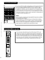
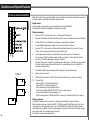
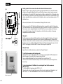
Fit the WLM2 master to a suitable wall. It will generally be found more convenient if the unit is within
0.8 metre of the manifold, as most thermal actuators are supplied with 1m cables. Cables can be run
on the surface into the terminals using either the cable releases in the cover or by pressing out the
cable entries in the lower part of the cover.
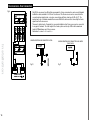
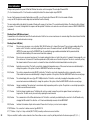
Electrical Installation
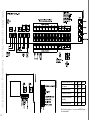
Fig. 3
PLEASE ENSURE THAT ALL WIRING IS CARRIED OUT IN ACCORDANCE WITH
LOCAL ELECTRICAL REGULATIONS.
When wiring is completed, fit the cover on the master using the screws provided.
Mains supply
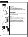
WLM2 requires a 230V AC mains supply connected to the terminals marked L, N, & E.
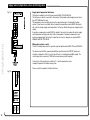
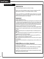
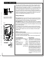
Boiler Demand
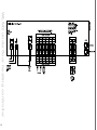
Fig. 4
The master has a volt-free relay output that can be used to control a boiler, or to open a
motorised valve.
A) To control a boiler that requires switching of the live supply, take a link from L (230V) to the
terminals marked BOILER - B1. Connect the boiler L to the terminal marked BOILER – B2.
Connect the boiler N terminal to the N terminal on the master, and the boiler E to the master
terminal E. (see fig. 7A).
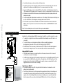
B) To control a boiler that has a pair of dedicated terminals for remote switching (e.g. by a Room
sensor), connect these terminals to B1 and B2 on the master. B1 and B2 terminals are “volt free”
so they can be used for both a 240V and a 24V circuit from the boiler.
9