1
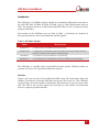
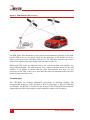
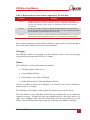
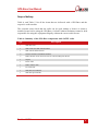
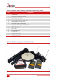
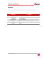
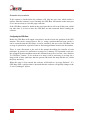
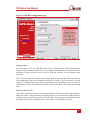
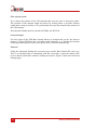
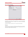
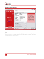
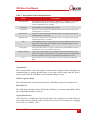
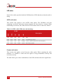
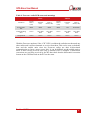
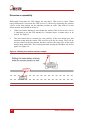
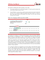
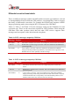
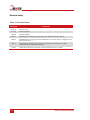
GPS-Base GPS Base Station GPS-Base User Manual Confidently. Accurately. Legal Notice Information furnished is believed to be accurate and reliable. However, Oxford Technical Solutions Limited assumes no responsibility for the consequences of use of such information nor for any infringement of patents or other rights of third parties which may result from its use. No license is granted by implication or otherwise under any patent or patent rights of Oxford Technical Solutions Limited. Specifications mentioned in this publication are subject to change without notice and do not represent a commitment on the part of Oxford Technical Solutions Limited. This publication supersedes and replaces all information previously supplied. Oxford Technical Solutions Limited products are not authorised for use as critical components in life support devices or systems without express written approval of Oxford Technical Solutions Limited. All brand names are trademarks of their respective holders. Copyright Notice © Copyright 2013, Oxford Technical Solutions. Revision Document Revision: 131025 (See Revision History for detailed information). Contact Details Oxford Technical Solutions Limited 77 Heyford Park Upper Heyford Oxfordshire OX25 5HD England Tel: +44 (0) 1869 238 015 Fax: +44 (0) 1869 238 016 http://www.oxts.com mailto:[email protected] 2 Oxford Technical Solutions GPS-Base User Manual Table of contents Introduction 5 Overview 5 Correction types 6 File logging 7 Features 7 Scope of delivery 9 Specification 11 Warranty 12 Conformance notices 13 Regulatory testing standards Operation and configuration 13 14 Choosing a suitable location 14 Connections 14 GPS-Base software 16 Choosing the connection 16 Choose port 17 Scan ports 17 Remember this port selection 18 Configuring the GPS-Base 18 Average position 19 Restore position from file 19 Enter antenna position 20 Leave unchanged 20 Advanced 20 Status page 21 Status 22 Revision: 131025 3 Communication 23 Latitude, longitude, altitude 23 Base Station ID 23 Logging Novatel binary 23 Logging RTCM V3 24 Save position to file 24 Start logging 25 LED status 26 SATEL radio status 26 Freewave radio status 26 Discussion on repeatability 28 Differential correction format details 30 Revision history 32 4 Oxford Technical Solutions GPS-Base User Manual Introduction The GPS-Base is a GPS Base Station suitable for transmitting differential corrections to the OxTS RT3000, RT4000, RT2002, RT2004, Survey+ and OEM products that use GPS. The position accuracy of differential and RTK GPS receivers is improved when using the GPS-Base. Four models of the GPS-Base exist, as listed in Table 1. All models are identical in their operation but are able to track different satellite signals. Table 1. GPS-Base Models Model GPS-Base-20 GPS-Base-20G GPS-Base-2 GPS-Base-2G Measurement L1 GPS corrections suitable for 20cm positioning L1 GPS and L1 GLONASS corrections suitable for 20cm positioning. Some RT products can achieve 2cm accuracy using this model. L1/L2 GPS corrections suitable for 2cm positioning L1/L2 GPS and L1/L2 GLONASS corrections suitable for 2cm positioning The GPS-Base is available with several different radio options. Different radios are required for license free operation in different countries. Overview Figure 1 gives an overview of how differential GPS works. The information from each satellite is measured by both the GPS-Base and by the GPS in the car. The GPS-Base works out the error in the satellite’s information and transmits it to the car using a radio link. The GPS in the car then applies the correction to each satellite’s measurement before it computes position and time. Revision: 131025 5 Figure 1. Differential GPS overview For RTK (Real-Time Kinematic) carrier-phase measurements the principle is the same, but the GPS in the car also has to figure out the difference in the number of carrierphase cycles between the GPS-Base and the car. The GPS-Base measures the carrierphase of the signals from each satellite and transmits it to the car. Differential GPS works in real-time because the corrections from each satellite vary slowly and predictably. The GPS in the car uses a model to predict the error from each satellite. It can update its model when the radio link transmits new data. It is not necessary for the GPS in the car to wait until the radio has transmitted the correction before it outputs its latest value. Correction types The GPS-Base can transmit differential corrections in different formats. The recommended format for OxTS products is RTCA (GPS-only) or RTCA2 (GPS and GLONASS). The RTCM V3 format can also be used. Table 2 lists the different formats supported by the GPS-Base and gives their suitability to other OxTS products. 6 Oxford Technical Solutions GPS-Base User Manual Table 2. Differential correction formats supported by the GPS-Base Format Purpose RTCA The RTCA format is suitable for GPS differential corrections for the RT3000, RT4000 and RT2002 products. The RTCA format is compatible with older RT3000 products (serial numbers below about 150). The RTCA format is not suitable for GLONASS. RTCA2 The RTCA2 format is suitable for GPS and GLONASS differential corrections for the RT3000, RT4000, RT2002 and RT2004 products. It is not compatible with older RT3000 products (serial numbers below about 150). RTCM V3 The RTCM V3 format is suitable for GPS and GLONASS differential corrections for the RT3000, RT4000 and RT2002 products. It is not suitable for RT2004 products. More detailed information on the different formats is given at the end of the manual in the section called “Differential correction format details”. File logging The GPS-Base software can log data on to the hard disk of the PC. Files can be logged in Novatel binary format and in RTCM V3 format. Features The GPS-Base is a self-contained unit that includes: The Base-Station GPS receiver. External Radio Modem. GPS Antenna, 15m Cable and Tripod. Radio Modem Aerial, Cable and Magnetic Mount. All that is needed to operate the GPS-Base is an external power source (normally a battery) and a PC or Laptop. The GPS-Base also includes a radio modem and antenna for use on the vehicle. The radio modem in your GPS-Base will be factory configured for use in a particular country or territory. Typically the radio can transmit between 2 km and 5 km line-ofsight. Trees, buildings, hills and other obstructions limit the range that can be used. Table 3 lists the different radio options that are commonly used with the GPS-Base. Revision: 131025 7 Table 3. Overview of different radios Radio SATEL 380 - 480 MHz band, up to 1 W, typically 5 km. License free bands available for many European countries. Radio will typically cover 8 bands with 25 kHz channel spacing. SATEL 869 MHz band, up to 500 mW, typically 2 km. License free across most of European Union. Freewave 900 MHz band, up to 1 W, typically >10 km. License free in USA, Brazil, Canada. Futaba 8 Specification 2.4GHz band, 10mW, typically more than 1km. License free in Japan. Oxford Technical Solutions GPS-Base User Manual Scope of delivery Table 4, and Table 5, list all the items that are delivered with a GPS-Base and the respective radio modem. The customer must check that the radio can be used without a license or obtain a suitable license before using the GPS-Base. Oxford Technical Solutions cannot be held responsible for using this equipment illegally without the correct radio license. Table 4. Summary of the GPS-Base components with SATEL radio Qty Description 1 GPS-Base Unit 1 GPS-C006 15m GPS Antenna Cable 1 GPS-702-GG GPS Antenna 2 SATEL Satelline-3ASd Radio Modem 2 Radio Modem Aerial/Antenna with 3m cable and Magnetic Mount 1 Tripod 1 Power cable 1 Radio modem cable 1 PC-USB cable 1 GPS-Base User Manual 1 GPS-Base Quick Guide Revision: 131025 9 Table 5. Summary of the GPS-Base components with Freewave radio Qty Description 1 GPS-Base unit 1 GPS-C006 15m GPS antenna cable 1 GPS-702-GG GPS antenna 2 Freewave FGR-115RC 900 MHz radio 2 14C0044B Freewave radio cable 1 Car antenna (short) with 20ft cable 1 Base-station antenna (long) with 20ft cable 1 Lightweight tripod 1 Power cable 1 Radio modem cable 1 PC-USB cable 1 GPS-Base user manual 1 GPS-Base quick guide Figure 2. GPS-Base components with SATEL radios 10 Oxford Technical Solutions GPS-Base User Manual Specification The technical specification of the GPS-Base unit is shown in Table 6, below. Table 6. Technical specification (except radio modem) Parameter Specification Power 6-18 V DC, 2 W Operating temperature -40 °C to +75 °C Environment Dry environments Relative humidity 95%, non-condensing Corrections RTCA (Differential, L1, L2), RTCA2, RTCM V3 Frequency 1 Hz Format Revision: 131025 RS232 11 Warranty Oxford Technical Solutions Limited warrants the GPS-Base products to be free of defects in materials and workmanship, subject to the conditions set forth below, for a period of one year from the Date of Sale. ‘Date of Sale’ shall mean the date of the Oxford Technical Solutions Limited invoice issued on delivery of the product. The responsibility of Oxford Technical Solutions Limited in respect of this warranty is limited solely to product replacement or product repair at an authorised location only. Determination of replacement or repair will be made by Oxford Technical Solutions Limited personnel or by personnel expressly authorised by Oxford Technical Solutions Limited for this purpose. In no event will Oxford Technical Solutions Limited be liable for any indirect, incidental, special or consequential damages whether through tort, contract or otherwise. This warranty is expressly in lieu of all other warranties, expressed or implied, including without limitation the implied warranties of merchantability or fitness for a particular purpose. The foregoing states the entire liability of Oxford Technical Solutions Limited with respect to the products herein. 12 Oxford Technical Solutions GPS-Base User Manual Conformance notices The GPS-Base complies with the radiated and conducted emission limits for CISPR 25 Level 2 and Class B of Part 15 of the FCC rules, and with the radiated emission and immunity limits for Class B of EN 61326. These limits are designed to provide reasonable protection against harmful interference in a residential installation. This equipment generates, uses and can radiate radio frequency energy and, if not installed and used in accordance with the instructions, may cause harmful interference to radio communications. However, there is no guarantee that interference will not occur in a particular installation. If this equipment does cause harmful interference to radio or television reception, which can be determined by turning the equipment off and on, the user is encouraged to try to correct the interference by one or more of the following measures: Re-orient or relocate the receiving antenna Increase the separation between the equipment and the receiver The GPS-Base conforms to the requirements for CE. Regulatory testing standards EN55025 CISPR 25 Level 2 EN 61000-4-2 EN 61000-4-3 EN 55001 (EN 61326) Class B Revision: 131025 13 Operation and configuration Follow these steps to operate your GPS-Base unit correctly. Choosing a suitable location For correct operation of the GPS-Base it is essential to locate the GPS antenna in a location where it has a full view of the sky, down to an elevation of 10 degrees in all directions. It must also be away from reflective objects, like buildings and trees. The GPS-Base unit should not be left in the rain or other wet conditions. Figure 3. GPS-Base location away from buildings, trees and reflective objects Connections Connect the GPS antenna to the tripod or to a secure pole. The mounting should ensure that the antenna does not move, including in wind or gusts (such as when a car drives past). Connect the GPS antenna cable to the GPS antenna and to the GPS antenna input on the GPS-Base unit. Note: Never extend or shorten the GPS antenna cable. The loss in the cable is carefully matched to the GPS-Base and lengthening or shortening the cable will reduce the performance of the GPS-Base system. 14 Oxford Technical Solutions GPS-Base User Manual Note: Never connect the GPS antenna to the radio aerial connector. The use of two TNC connectors is required since they have much better ground properties compared to BNC connectors. The radio aerial output has a high-power signal that may damage the GPS antenna. Locate the radio modem aerial at least 2m away from the GPS antenna. Clip the radio modem aerial on a metal object, such as the roof of a car. Connect the radio modem aerial to the radio aerial connector on the GPS-Base unit. OxTS has alternative aerials that are suitable for attaching to buildings and do not require a ground-plane under the aerial. Figure 4. GPS-Base connections Figure 4, above, shows the connections for the GPS antenna and the radio aerial. Revision: 131025 15 GPS-Base software The GPS-Base software is used to configure the GPS-Base and monitor its operation. With the software you can: a) Average base-station location b) Enter base-station location, if known c) Restore a saved base-station location d) Program a location in to the GPS-Base so it will use it after power is removed and restored e) Set the base-station identifier in to the GPS-Base f) Change the format of the corrections g) Monitor the status of the GPS-Base h) Save differential correction data to disk The GPS-Base software is organised as a wizard that will guide you through the operation of the GPS-Base. Choosing the connection Figure 5 shows the software when it is first run. The left hand side shows which step of the wizard you are currently on. Pages can be jumped by clicking on the steps on the left hand side. 16 Oxford Technical Solutions GPS-Base User Manual Figure 5. GPS-Base software Choose port To communicate with the GPS-Base the software needs to know which “port” the GPSBase is connected to. The GPS-Base connects using USB but the USB drivers makes the GPS-Base appear as a serial COM port. Normally the driver will install three COM ports for the GPS-Base: COM5, COM6 and COM7. Any of these can be used. If these ports are taken by other software drivers then other ports will be used and it will be necessary to “search” until the correct port is found. The GPS-Base automatically scans all the available ports on start up and only lists the ports where a valid GPS-Base has been detected. Scan ports If the GPS-Base was not connected when the software was run then the list will be blank. Press the Scan Ports button to rescan the ports and find the GPS-Base. Revision: 131025 17 Remember this port selection If this option is checked then the software will skip the port scan, which makes it quicker when the software is run. Normally the GPS-Base will remain on the same port so it is not necessary to visit this page each time. If the GPS-Base cannot be found on the saved port then it will scan all the ports, which can take time. It is best to have the GPS-Base on and connected before starting the software. Configuring the GPS-Base Before the GPS-Base will output corrections it needs to know the position of the GPS antenna. This can be restored from a file (i.e. using a position that has been saved), it can be restored from the GPS-Base, it can be entered by the user or the GPS-Base can average its position for a period of time to find an approximate location for the antenna. There is some discussion at the end of the manual describing the benefits of each technique. In general it is sufficient to average for 3 minutes. For repeatable work save the averaged location and then restore this location from a file or use the “Save Position To GPS Base” feature. To be accurate to a map it will be necessary to average for a long period of time (and hope that the person who made the map did this too, which they may not have). When this page is first entered the software will default to “Average Position”. If a GPS-Base with a valid position is detected then the software will quickly change to the “Leave Unchanged” option. 18 Oxford Technical Solutions GPS-Base User Manual Figure 6. GPS-Base configuration page Average position Use this option to let the GPS-Base find its own position using GPS measurements. This is the most common option to use. For temporary installations a 3 minute period is sufficient. Longer periods can be used to find the location of the antenna more precisely. Note: if you average for 3 minutes then all the data for this average will be accurate to 2cm compared to other data obtained during this average. If you re-average you will end up in a different location and the data from the new location will not overlay the old location. Use the Save/Restore features so that future data will overlay the current data. Restore position from file If you have saved the location of the GPS antenna to a file then you can restore that file using this option. This guarantees repeatable data if you can locate the GPS antenna in exactly the same location each time. The GPS-Base can also store an antenna location internally, this will be explained in the “Save Position To GPS Base” section. Revision: 131025 19 Enter antenna position If you know the position of the GPS antenna then you can enter it using this option. The position of the antenna might be known by writing down a previous location (rather than saving it to disk) or if a professional surveyor has measured the position of the GPS antenna. Note that the altitude must be entered in EGM96, not WGS-84. Leave unchanged Use this option if the GPS-Base already knows its location and you do not want to change it. If the GPS-Base has a location stored internally, or a location has already been acquired during the session, this option will be selected automatically. Advanced Using the Advanced Settings the correction type and the Base Station ID can be set. This is an identifier that is transmitted with the corrections so that the mobile GPS receiver knows which base-station is sending corrections. Figure 7 shows the Advanced Settings page. 20 Oxford Technical Solutions GPS-Base User Manual Figure 7. Advanced settings page The GPS-Base supports RTCA, RTCA2 and RTCM V3 corrections. More detailed information about these formats is available in the section called “Differential correction format details”. By default the GPS-Base will transmit “OxTS” as the Base Station Identifier. Status page The Status page is used to monitor the GPS-Base. The GPS-Base does not need the PC software to be running continuously, once the GPS-Base is configured then the PC can be disconnected. Figure 8 shows the Status Page. Revision: 131025 21 Figure 8. GPS-Base status page Status The status parameter shows the status of the GPS-Base and the software. Valid values for this parameter are listed in Table 7. 22 Oxford Technical Solutions GPS-Base User Manual Table 7. Description of the status parameters Value Not Connected Description The GPS-Base software cannot find a GPS-Base to communicate with on the selected port. Return to the Connection page to select a different port or connect a GPS-Base to the computer. Averaging The GPS-Base is averaging the GPS positions. RTCA OK This is the normal mode for the GPS-Base when it is working correctly and outputting RTCA corrections. RTCA2 OK This is the normal mode for the GPS-Base when it is working correctly and outputting RTCA2 corrections. RTCMV3 OK This is the normal mode for the GPS-Base when it is working correctly and outputting RTCM V3 corrections. Idle Interrogating Integrity Warning Error The GPS-Base is idle. To change from this mode the GPS-Base needs to know the position of the GPS antenna. Return to the Configuration page to set the location of the GPS antenna. In this mode the software is trying to communicate and establish the mode of the GPS-Base. This mode should not last long. This occurs when the GPS receiver disagrees with the position that is being used. Check that the antenna location corresponds to the position that has been entered or that the file used to save the GPS antenna location is correct. There is some error. It is probably best to restart the software and the GPSBase. Communication The Communication value will change to show that the computer and the GPS-Base are communicating. In normal operation none of the other values change and this field is useful to show that the GPS-Base is still communicating correctly. Latitude, longitude, altitude These measurements show the location that the GPS-Base believes the antenna is at. Base Station ID This field shows the Base Station ID that the GPS-Base is currently transmitting. When this is blank then no ID has been set. Logging Novatel binary If the software is configured to log Novatel binary data to disk (for use with GPS postprocessing software) then the value will show the size of the file. Otherwise, if logging is not active, it will show “Off”. Revision: 131025 23 Logging RTCM V3 If the software is configured to log RTCM V3 data to disk then the value will show the size of the file. Otherwise, if logging is not active, it will show “Off”. Currently OxTS software does not support this format for post-processing but may use it in the future. Save position to file Use this option to save the current location of the GPS antenna to a file. The file can later be restored. To use the save position feature it is also necessary to be able to replace the GPS antenna to exactly the same position each time. A 1cm difference in the location of the GPS antenna will result in a 1cm difference in the location of the remote RT measurements. Save position to GPS-Base Use this option to store the current antenna location internally on the GPS-Base. When a location is stored in the GPS-Base, there is no need to re-configure it every time it is used. Simply turn the GPS-Base on, without connecting it to a computer, and it will start transmitting corrections using the saved antenna location and differential correction format. When using this feature it is necessary to replace the GPS antenna in exactly the same position each time. Only one antenna location can be stored on the GPS-Base, if a new location is stored it will overwrite the old one. To find out which antenna location is stored in the GPS-Base, it must be connected to a computer and the software must be used. If there is a location stored on the GPS-Base, “Leave Unchanged” will automatically be selected on the Configuration page. This option will display the location stored in the GPS-Base on the Status page. If the position of the antenna is re-averaged or if a new position is sent, any location stored on the GPS-Base will be erased. After averaging or sending a new position, it will be necessary to save the position to the GPS-Base. Save setting to GPS-Base While the GBS-Base is averaging the “Save Position To GPS-Base” function will change to “Save Setting To GPS-Base”. Instead of saving the position to the GPS-Base this will instruct the GPS-Base to average a new position when it is turned on. This can be useful so that the GPS-Base works without a PC connected and averages its position when it is turned on. It will then output the differential corrections when it has finished averaging. 24 Oxford Technical Solutions GPS-Base User Manual Start logging Use this option to start logging the raw GPS measurements from the GPS-Base. Once started the “Start Logging” button will become “Stop Logging” which will stop the logging of the raw GPS measurements when pressed. While logging it is not possible to change page or quit. Revision: 131025 25 LED status Some of the radios provided with the GPS-Base have LEDs that show what the radio is doing. SATEL radio status This section only applies to the SATEL radio option. The GPS-Base will start outputting corrections when the antenna location has been found or entered. When transmitting corrections, the LEDs on the SATEL modem will be as shown in Table 8. Table 8. SATEL radio LED states and meanings LEDS RTS CTS TD RD CD Description Off Red Off Off Off Idle Off Red Red Off Red Transmitting a packet Off Red Off Off Orange Noise or other transmission on this frequency Off Red Off Green Green Receiving a packet Freewave radio status This section only applies to the Freewave radio option. When operating the radio modems it is sensible to check that the signal is being transmitted correctly and received correctly. The table below gives some combinations of the LEDs and describes their significance. 26 Oxford Technical Solutions GPS-Base User Manual Table 9. Freewave radio LED states and meanings Base Mobile Condition Carrier Detect (CD) Transmit (TX) Clear to Send (CTS) Carrier Detect (CD) Transmit (TX) Clear to Send (CTS) Powered No link RED RED RED RED Off Red Flash Linked Sending data Green Slow Red flash Slow Red flash Green Slow Red flash Slow Red flash Setup Mode Green Green Green Green Green Green With the Freewave modems, if the “CD” LED is red then the radio has not detected any other radios and it will not transmit or receive from them. This can be seen on both the base and the mobile units since the Freewave radios use their bi-directional communication to form a more secure link. It can be difficult on the mobile unit to know if data is being received since only a transmit LED is available. If differential corrections are not being received by the RT then check that the differential correction format on the GPS-Base and on the RT are the same. Revision: 131025 27 Discussion on repeatability Differential Corrections for GPS change the way that a GPS receiver works. When using Differential Corrections the GPS receiver is effectively measuring the position relative to the base-station, not the absolute position on earth. This leads to several effects that the user should be aware of: 1. If the base-station antenna is moved then the remote GPS receivers move too. It is important to put the GPS antenna in a location where it cannot move or be moved. See Figure 9. 2. The base-station has to measure its own position. If the base-station gets this position wrong then the remote GPS receivers will also be wrong. They will be correct relative to the base-station, but they will have the same error on the earth that the base-station has. This is important when turning the GPS-Base off and on again. See Figure 10. Figure 9. Shifting base-station antenna example 28 Oxford Technical Solutions GPS-Base User Manual The problem of shifting the antenna typically occurs when: The tripod is knocked over and picked up again. It is hard to get the antenna back to the same location accurate to 1cm. If the GPS-Base is used one day, packed up then returned to the same location the next day. It is very hard to replace the tripod in the same location. It is better to have a pole that is fixed to the ground if you intend to use the same surveyed location on several days. Figure 10. Averaging to a different position example The problem of averaging to a different position happens each time that the GPS-Base goes through its averaging process. There is nothing magical about the GPS-Base that allows it to get its own position accurate to 2cm or better. It is subject to the same errors that all GPS receivers have and can only average its position to about 1.8m CEP. If the user is prepared to wait a long time (typically more than 24 hours) then GPS is able to improve the accuracy of the base-station antenna so it is accurate to 2cm or better. However, since the timescale for this is long it is not usually practical, except for permanent installations. (Even when you have a permanent installation it is not required since all it does is allows you to relate your measurements to a surveyors measurements and this is rarely required). To overcome the problem of averaging the save/restore feature of the GPS-Base should be used. When using the Save/Restore feature the GPS-Base will save the position where it last averaged and then use this next time (instead of averaging again). This way the error is the same each time and the repeatability is perfect. You must remember to put the antenna in the same location each time, accurate to 1cm or better, when using the Save/Restore feature. Revision: 131025 29 Differential correction format details There are different messages within each differential correction type and these can lead to incompatibilities between different GPS products, even though they claim to support the family of differential corrections. For example the RT2004 only supports its RTK Integer positioning mode when using the RTCA2 format of the GPS-Base. Table 10, Table 11 and Table 12 list the messages output by the GPS-Base for each correction type. These are the corrections required for OxTS products. When using the GPS-Base with other products check that the other GPS receiver supports these messages and can operate in the desired mode using them. Table 10. RTCA messages output by GPS-Base Message Period Purpose RTCAREF 10s Information about the base-station, for example the position of the base-station. RTCA1 1s Differential or pseudo-range corrections. These are suitable for the differential positioning mode. RTCAOBS 1s Carrier-phase corrections. These are suitable for the RTK Float and RTK Integer positioning modes using GPS only. GLONASS is not supported, so the RT2004 does not work optimally with this message. Table 11. RTCA2 messages output by GPS-Base Message Period RTCAREF 10s Information about the base-station, for example the position of the basestation. RTCA1 1s Differential or pseudo-range corrections. These are suitable for the differential positioning mode. RTCAOBS2 1s Carrier-phase corrections. These are suitable for the RTK Float and RTK Integer positioning modes using GPS and GLONASS. This format is required so that the RT2004 will work optimally. The older RT3000 products (serial numbers below about 150) cannot use this new message. 30 Purpose Oxford Technical Solutions GPS-Base User Manual Table 12. RTCM V3 messages output by GPS-Base Message Period RTCM 1003 1s GPS differential corrections including carrier-phase and pseudo-range corrections. RTCM 1006 5s Base-station parameters information. RTCM 1007 10s Antenna information. RTCM 1011 1s GLONASS differential corrections including carrier phase and pseudo-range corrections. Revision: 131025 Purpose 31 Revision history Table 13. Revision history Revision Comments 070330 Initial Version. 071128 Software Updates. 080916 Software Updates. 090917 Added Advanced Settings for Base Station ID. Added GLONASS options. 100812 Added RTCM V3 logging, RTCA2 and RTCM V3 correction outputs. Changed to new radio modem cable. 120111 Updated images and drawings to match new enclosure and connectors. Added compatibility with RT2002 and RT2004. 131025 Update image showing connections, minor formatting and new products. 32 Oxford Technical Solutions