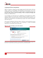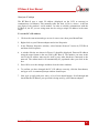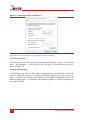
1
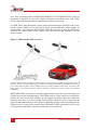
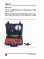
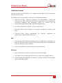
RT-Base S Portable GNSS Base Station User Manual Confidently. Accurately. Legal Notices Information furnished is believed to be accurate and reliable. However, Oxford Technical Solutions Limited assumes no responsibility for the consequences of use of such information nor for any infringement of patents or other rights of third parties which may result from its use. No license is granted by implication or otherwise under any patent or patent rights of Oxford Technical Solutions Limited. Specifications mentioned in this publication are subject to change without notice and do not represent a commitment on the part of Oxford Technical Solutions Limited. This publication supersedes and replaces all information previously supplied. Oxford Technical Solutions Limited products are not authorised for use as critical components in life support devices or systems without express written approval of Oxford Technical Solutions Limited. All brand names are trademarks of their respective holders. The software is provided by the contributors “as is” and any express or implied warranties, including, but not limited to, the implied warranties of merchantability and fitness for a particular purpose are disclaimed. In no event shall the contributors be liable for any direct, indirect, incidental, special, exemplary, or consequential damages (including, but not limited to, procurement of substitute goods or services; loss of use, data, or profits; or business interruption) however caused and on any theory of liability, whether in contract, strict liability, or tort (including negligence or otherwise) arising in any way out of the use of this software, even if advised of the possibility of such damage. Copyright Notice © Copyright 2015, Oxford Technical Solutions. Revision Document Revision: 151112 (See Revision History for detailed information). Contact Details Oxford Technical Solutions Limited 77 Heyford Park Upper Heyford Oxfordshire OX25 5HD United Kingdom 2 Tel: +44 (0) 1869 238 015 Fax: +44 (0) 1869 238 016 Web: http://www.oxts.com Email: [email protected] Oxford Technical Solutions RT-Base S User Manual Warranty Oxford Technical Solutions Limited warrants its products to be free of defects in materials and workmanship, subject to the conditions set forth below, for a period of one year from the Date of Sale. ‘Date of Sale’ shall mean the date of the Oxford Technical Solutions Limited invoice issued on delivery of the product. The responsibility of Oxford Technical Solutions Limited in respect of this warranty is limited solely to product replacement or product repair at an authorised location only. Determination of replacement or repair will be made by Oxford Technical Solutions Limited personnel or by personnel expressly authorised by Oxford Technical Solutions Limited for this purpose. In no event will Oxford Technical Solutions Limited be liable for any indirect, incidental, special or consequential damages whether through tort, contract or otherwise. This warranty is expressly in lieu of all other warranties, expressed or implied, including without limitation the implied warranties of merchantability or fitness for a particular purpose. The foregoing states the entire liability of Oxford Technical Solutions Limited with respect to the products herein. Revision: 151112 3 Table of Contents Introduction 5 How do base stations work? 5 Transmitting the corrections 7 Scope of delivery 8 Specification 10 Conformance notices 11 EMC 11 ESD notice 11 Operation 12 Charging the internal battery To disconnect the battery 12 13 Selecting a suitable antenna location, and setting up the tripod 13 Connecting the GNSS antenna and radio modem cables 15 Powering up and monitoring the RT-Base S The control panel 16 16 Configuring the RT-Base S using NAVbase Check your IP settings The NAVbase interface 20 21 22 Position manager 27 Downloading and converting the internally logged correction data 29 Attaching the second modem 31 Changing the differential correction format 32 What the RT-Base S transmits in each mode 32 Repeatability 34 Revision history 36 4 Oxford Technical Solutions RT-Base S User Manual Introduction The RT-Base S is a self-contained, weatherproof and portable GNSS base station. It is designed to be quick and easy to set-up, and transmits corrections to local receivers via radio modem or (optionally) via Wi-Fi. In addition to outputting differential corrections for use in real-time, the RT-Base S has the ability to log corrections internally—allowing them to be used in post-processing. This is especially useful when operating in challenging real-world environments because it means no data is lost where the reliability of radio transmissions cannot be guaranteed. There are two versions of the RT-Base S: RT-Base S Supplies L1/L2 GPS corrections down to 1 cm accuracy. RT-Base S G Supplies GLONASS and L1/L2 GPS corrections down to 1 cm accuracy. How do base stations work? A base station significantly increases the position accuracy of other GNSS receivers by sending them corrections. The base station does this by independently identifying the errors affecting the signal from each GNSS satellite it can see. Information about those errors is then broadcast using a radio modem, or something similar. Other GNSS receivers in the area—which are also connected to similar radio modems—receive the correction information and take it into account when calculating their own position measurements. Removing the errors results in more accurate position estimates. A base station identifies the errors affecting GNSS signals in one of two ways. If the base station is placed at a precisely surveyed location, it calculates a GNSS position measurement in the normal way, then compares that calculated position to the known location. If the position measurements match exactly, no correction is required. If there is a difference however, the base station calculates the length of time each satellite signal would need to be delayed by, in order to cause the difference between the surveyed location and the GNSS measurement being produced. Alternatively, if the base station is not placed at an accurately surveyed location, the only way for it to estimate the errors is to measure its own position as accurately as possible. It does this by averaging the GNSS measurements over a period of time before settling on one location. It then compares all further measurements to that chosen location in order to identify the errors in the same way as before. In both cases the base station calculates the errors affecting the signal from each satellite it can see, and shares that information with other GNSS receivers in the local Revision: 151112 5 area. This is normally achieved using radio modems or via an optional Wi-Fi system. A transmitter connected to the base station broadcasts corrections, and each GNSS receiver has a modem attached to it that listens for those corrections. For RTK (Real-Time Kinematic) carrier-phase measurements the principle is the same, but the remote GNSS receiver also has to figure out the difference in the number of carrier-phase cycles between the RT-Base S and the itself. To do this, the RT-Base S measures the carrier-phase of the signals from each satellite and transmits it to the remote system. Figure 1. Differential GNSS overview The base station is either placed at a precisely known location or left to average its position over time. It can then estimate the errors affecting each satellite it is tracking and broadcast information about those errors using radio modems. Nearby GNSS receivers use radio modems to listen for corrections, and apply them to the signals from the common satellites, reducing the errors in their own position calculations. Differential GNSS can work in real-time applications because the errors affecting each satellite vary slowly and predictably. The GNSS receiver in the vehicle uses a model to predict the error from each satellite. It can update its model when the radio link transmits new data. It is not necessary for the mobile GNSS receiver to wait until the radio has transmitted the correction before outputting its latest value. Depending on the GNSS receiver in your INS, pseudo-range differential GNSS corrections can be up to 60 seconds old, and RTK corrections can be up to 30 seconds old. 6 Oxford Technical Solutions RT-Base S User Manual Transmitting the corrections Each new RT-Base S is supplied with a pair of radio modems suitable for use in the country specified when ordered. Typically, these radio modems have a range of 2–5 km line-of-sight. However, trees, buildings, hills and other obstructions will limit the range that can be achieved. Table 1 shows the different radios that can be supplied with the RT-Base S. Please note, one of the radio modems will be pre-installed inside the RT-Base S. Table 1. Overview of different radios Radio Specification SATEL 403–473 MHz band, up to 1 W, typically 5 km. License free bands available for many European countries. Radio will typically cover 8 bands with 25 kHz channel spacing, except for SATEL Easy radios which have a much wider range of configurable frequency. SATEL 869 MHz band, up to 500 mW, typically 2 km. License free across most of European Union. FreeWave 900 MHz band, up to 1 W, typically >10 km. License free in USA, Brazil, Canada. Futaba 2.4 GHz band, 10 mW, maximum 2 km. License free in Japan. As an option, the RT-Base S can broadcast corrections via Wi-Fi using an RT-XLAN. The RT-XLAN transmits DGNSS corrections up to 1 km and is an especially useful feature for customers using our newest RT-Range systems, as it means the corrections can be received by just one INS, then shared among the other vehicles without the need for additional equipment. While the RT-Base S will work seamlessly with our own GNSS-aided INS products, it is not limited to them in any way. The RT-Base S can also serve as a general base station for other products. To help achieve this the RT-Base S transmits corrections in six common formats: RTCA, RTCA2, RTCM, RTCMv3, CMR, CMR+. Revision: 151112 7 Scope of delivery Table 2 lists all the standard items that are delivered with an RT-Base S. Table 3, Table 4 and Table 5 list additional components that are supplied, depending on the radio modem being supplied. Please note: the customer must check that the supplied radio can be used without a license, or obtain a suitable license before using the RT-Base S. Oxford Technical Solutions cannot be held responsible for using this equipment illegally without the correct radio license. Figure 2. RT-Base S components 8 Oxford Technical Solutions RT-Base S User Manual Table 2. Summary of the common RT-Base S components Qty. Description 1 RT-Base S unit 1 GPS-C006 15 m GNSS antenna cable 1 GPS-702-GG GNSS antenna 1 Professional tripod 1 12.8 V, 10 Ah, LiFePO4 battery (pre-installed) 1 13.2 V battery charger and cable (UK, EU and US-adapters supplied) 1 RT-Base S user manual Note 1: Other radio modems/antennas might be supplied depending on the region it is used in. Table 3. Additional components when supplied with SATEL radios Qty. Description 2 SATEL Satelline-3ASd radio modems—one modem is pre-installed into the RT-Base S 2 Radio modem antenna with 3 m cable and magnetic bases Table 4. Additional components when supplied with FreeWave radios Qty. Description 2 FreeWave FGR-115RC 900 MHz radio modems—one modem is pre-installed into the RT-Base S 2 Radio modem antenna with 3 m cable and magnetic bases Table 5. Additional components supplied with Futaba radios Qty. Description 2 Futaba radio modems—one modem is pre-installed into the RT-Base S 3 Radio antenna, SMA connector and magnetic base 2 2 m SMA-SMA antenna extension cable 1 5 m SMA-SMA antenna extension cable 1 TNC-SMA adaptor (fitted to one of the radio antennas) 1 14C0045A RT3000 Futaba radio cable Revision: 151112 9 Specification The technical specification of the RT-Base S unit is shown in Table 6. Table 6. RT-Base S specification Parameter Specification Power rating 12 V dc, 2.5 A maximum Mains power 110–240 V ac, 50–60 Hz, 3 A maximum Battery 12.8 V, 10 Ah, LiFePO4 Charge time ≈ 6 hours Operating time 30 hours typical (>24 hours at -10 °C) Operating temperature -10–50 °C Charge temperature -20–40 °C Environment IP65 when lid is secured shut Output format RTCA, RTCA2, RTCM, RTCMv3, CMR, CMR+ Output interface RS232 serial, Ethernet Case dimensions 474 × 415 × 149 mm (external) Mass 11.9 kg (inc. all accessories) Please note: The casing of the RT-Base S is air-tight when closed, but it is fitted with a one-way valve to release excess pressure. If the RT-Base S has been transported by air, it may be necessary to open the valve (located behind the handle) to balance the air pressure inside the case before it can be opened. 10 Oxford Technical Solutions RT-Base S User Manual Conformance notices Any use or misuse of the RT-Base S, in a manner not intended by OxTS, may impair the protection provided. The RT-Base S has been tested to, and passed, the following standards: EN 61326-2-1:2013 Electrical equipment for measurement, control and laboratory use. EMC requirements. Particular requirements. Test configurations, operational conditions and performance criteria for sensitive test and measurement equipment for EMC unprotected applications. FCC Rules CFR 47:2013 Parts 15.107 & 15.109 Class A. EN 60529:1992+A2:2013 Degrees of protection provided by enclosures (IP code). EN 61010-1:2010 Safety requirements measurement, control, and laboratory use. for electrical equipment for EMC The antennas used with this transmitter must be installed with a separation of at least 23 centimetres from all persons. The antennas must also be separated by at least 20 centimetres from each other. Only screened Ethernet cables should be used with this unit. ESD notice The LCD display is sensitive to electro-static discharge (ESD). The display may go blank when ESD occurs to some parts of the RT-Base S. Other components in RT-Base S continue to operate correctly even if display appears blank due to ESD. Revision: 151112 11 Operation The RT-Base S has been designed to be as easy to operate as possible. However, it is important to have a sound understanding of how the system works, so please read the manual thoroughly before operating the product. The set-up procedure is summarised below. More detailed information on each step is also presented in the following sections. Process of setting up the RT-Base S: 1. Ensure the battery is charged (page 12). 2. Select a stable, suitable location for the GNSS antenna (page 13). 3. Connect all cables and power up the system (page 15). 4. Configure the system, if required (page 15). 5. Download and convert the data if required (page 29). Charging the internal battery The RT-Base S is fitted with a 12.8 volt, 10 amp-hour, LiFePO4 battery. The battery is capable of running the RT-Base S for between 24 and 32 hours depending on conditions. Before using the RT-Base S for the first time, and prior to use each day, the battery should be fully charged. To charge the battery, connect the M12 connector on the supplied charger to the connector marked Charge on the RT-Base S, then plug the battery charger in to the mains supply. Note that the M12 connector is keyed and will only fit when correctly aligned. The screw-collar only needs to be finger-tight. An LED on the battery charger show the current charging state (yellow = charging, green = fully charged). The RT-Base S takes about six hours to charge from fully discharged. General precautions Do not replace the batteries in the RT-Base S. Only charge the RT-Base S with the supplied charger. Do not charge the batteries more than once without discharging. Do not expose the charger to water. Charging should take place indoors. Do not leave the RT-Base S unattended during charging. 12 Oxford Technical Solutions RT-Base S User Manual Do not use the charger if there are signs of damage. Do not cover the charger. To disconnect the battery The battery is connected to the RT-base S using an M12 connector. To fully disconnect the battery, it is necessary to remove the modem panel as shown in Figure 3. This panel is held in place using three thumb-screws. Remove the screws and lift out the panel using the two small handles attached to the cover. The battery can be disconnected by simply unscrewing the connector. Figure 3. Disconnecting the battery To disconnect the battery, remove the three thumb screws (red circles) securing the modem panel. The radio and battery connectors are indicated in the image above. To disconnect the battery, unscrew the connector. Selecting a suitable antenna location, and setting up the tripod For the RT-Base S to work to specification, it is essential to put the antenna in a location where it has a clear view of the sky. GNSS antennas do not only look for satellites from above, they also receive signals from the side—down to an elevation of 10° in all directions. For that reason, it is important to place the antenna in the most open location available to you. One error that no base station can easily correct for are multi-path reflections from buildings and trees. To avoid these, do not locate the antenna near trees and buildings, or other tall hard structures. It is also very important that the antenna does not move during the test. Ensure the supplied tripod is stable enough not to move in the wind and Revision: 151112 13 that no one can bump into it. When performing vehicle tests, consider gusts of wind that may be created by passing vehicles. Figure 4. Choosing a location for the GNSS antenna Choose a location for the GNSS antenna that is not close to buildings or trees, as these can both affect GNSS signals. The antenna needs to have a good view of the sky (not just above, but to the sides too). If you intend to perform a test over several days, and will be packing the base-station away overnight, it is important to mark the location of the GNSS antenna. It will need to be placed in precisely the same location on each day. If possible, mount the antenna on a pole that has been fixed in the ground and can be left behind until the test has finished. When operating in hot environments, the RT-Base S unit should not be left in direct sunlight or the internal temperature may exceed the specification. The temperature range of the unit is restricted because of the internal battery. Setting up the tripod and antenna 1. The tripod legs use a friction lock to maintain their position. To extend each leg, twist each leg axially in an anti-clockwise direction (viewed from below) to unlock the leg. Ensure each section is re-locked in position by axially twisting it in a clockwise direction. It doesn’t matter how high the GNSS antenna is located, as long as it has the best possible view of the sky. 2. Carefully remove the GNSS antenna from the RT-Base S case. The antenna is attached to the tripod via the threaded section. Do not apply excessive force when tightening the antenna. 14 Oxford Technical Solutions RT-Base S User Manual 3. Ensure the tripod and antenna are located in safe position and there is no chance there will move or fall-over. Connecting the GNSS antenna and radio modem cables Before powering up the RT-Base S, the GNSS antenna should be connected to the GNSS connector using the supplied GNSS cable. The GNSS connector on the RT-Base S is located to the left of the carry handle. Figure 5. RT-Base S cable connections As shown above, the GNSS antenna connects to the left of the handle and the radio modem connects to the right. Do not swap the connectors over or damage may occur. If radio modems are being used to transmit and receive DGNSS corrections, one of the supplied antennas should be connected to the Radio connector, located to the right of the carry handle. The radio modem antenna should be placed as high up as possible (to ensure good range is achieved), but should be located at least 20 centimetres from the GNSS antenna. Cable connection summary Before powering the system, connect the GNSS antenna to the GNSS connector using the supplied GNSS cable. If radio modems are not required, there is no need to connect the radio modem antenna to the Radio connector. If modems are being used, connect the antenna before powering up the RT-Base S. Ensure the radio modem is at least 20 centimetres from the GNSS antenna. Revision: 151112 15 Powering up and monitoring the RT-Base S The RT-Base S is switched on and off using the Power button located on the control panel. If the LCD display fails to illuminate or show data, ensure the battery is charged and that the battery has been reconnected after air travel. Please note that a number of factors affect the time taken for the RT-Base S to acquire satellites. The process normally takes about 90 seconds, but can take up to 20 minutes if the unit has been turned off for a long period of time or has been moved a significant distance since last time it was used. The first thing the RT-Base S loads as part of the boot process is a configuration file, which is held in its internal memory. The configuration file controls how the RT-Base S behaves. The first time an RT-Base S is powered up after delivery, the default settings are used. The default settings tell the RT-Base S to average its position over a three-minute period (once it computes a GNSS position) and to broadcast corrections in RTCMv3 format. The base station ID will be set to OxTS. Creating custom configurations using our NAVbase software is covered in the next section. Before that, it is important to become familiar with information presented on the LCD display, and to learn how to adjust basic parameters of the configuration using only the built in controls. This is useful in case you need to check/modify the RT-Base S during a test but don’t have immediate access to a portable computer. The control panel The control panel on the RT-Base S is made up of three buttons, an LCD, a charge connector, an Ethernet port and power switch. The controls and LCD are shown in Figure 6. Figure 6. The control panel on the RT-Base S 16 Oxford Technical Solutions RT-Base S User Manual When power is first applied, the LCD display shows the firmware version running in the RT-Base S along with and the static IP address the unit is using to communicate (Figure 7). This information page is displayed for 10 seconds. Figure 7. LCD boot screen shown at start-up Dev ID and IP address being used. This page is displayed for 10 seconds when power is first applied. As soon as the boot page disappears, the LCD begins to alternate between the two different status pages shown in Figure 8—displaying each for eight seconds. Once a valid position measurement has been calculated, the system will begin to average a position using the time period specified in the configuration file. At this point the LCD alternates between the pages shown in Figure 9. Once averaging is complete, or once an existing location has been loaded from memory, the LCD moves to the fixed position status pages shown in Figure 10. The RT-Base S can now be considered to be functioning. Figure 8. LCD status pages while searching for a valid GNSS solution The LCD alternates between the two screens above at eight second intervals while it looks for a valid GNSS position. Figure 9. LCD status pages while averaging a GNSS position The LCD alternates between the two screens above at eight second intervals while it averages a position. This process can be interrupted at any time and a saved position can be loaded. Revision: 151112 17 Figure 10. LCD status pages once position is fixed The LCD alternates between the two screens above at eight second intervals once a position has either been averaged over the specified time period, or a saved location has been loaded. Making adjustments using the built-in control panel Once the system has booted, the Scroll, Menu/Enter and Back buttons located on the control panel can be used to access the internal menu system. This menu system provides an easy way to adjust the main settings used by the RT-Base S. The layout of the menu system is shown in Figure 11. 18 Oxford Technical Solutions RT-Base S User Manual Figure 11. RT-Base S settings menu layout and navigation The settings menu can be accessed at any time from the status pages by pressing the Menu/Enter button. This image shows how the settings menu is laid out. Once an option has been chosen, a brief confirmation message (not shown here) will be displayed. Revision: 151112 19 Configuring the RT-Base S using NAVbase While it is possible to change most major settings using the built-in buttons and menu system, in order to use all features of the RT-Base S, you will need to use our free configuration software. Each RT-Base S is supplied with a CD containing a copy of our latest NAVsuite software. NAVsuite contains a number of different applications that are used to help you work with OxTS hardware. The one required to configure the RT-Base S is called NAVbase. To use NAVbase you will need access to a Windows PC with an Ethernet port. Before using the RT-Base S for the first time, NAVsuite should be installed on your PC. To install the software, insert the CD into the CD drive and follow the instructions of the installer. If the installer fails to run automatically, navigate to the CD drive and doubleclick NAVsetup.exe. Once you have installed the NAVsuite software, NAVbase can be launched by pressing the Windows key and typing navbase, or by navigating to it under the installed applications. You will find it in the OxTS folder. Figure 12. Allow NAVbase to access the network The first time NAVbase is started, Windows Firewall may present a warning message. You must allow NAVbase access to the Ethernet network, or it will not be able to communicate with the hardware. It is best to allow communication via private and public networks to prevent future problems. 20 Oxford Technical Solutions RT-Base S User Manual Check your IP settings The RT-Base S uses a static IP address (displayed on the LCD at start-up) to communicate via Ethernet. This normally takes the form 195.0.0.s, where s is the last two digits of the product’s serial number. In order to reliably communicate with the RT-Base S, the PC you are using must also be using a unique IP address in the same range. To set the PC’s IP address; 1. Click on the start menu and type network connections, then press Menu/Enter. 2. Right-click on your Ethernet adaptor and select Properties. 3. In the Ethernet Properties window, select Internet Protocol Version 4 (TCP/IPv4) and then click Properties. 4. A window like the one shown in Figure 13 should be displayed. Enter an IP address using the same format as the one used by RT-Base S. The number you enter at the end of the IP address must not be used by any other hardware connected to the network. The subnet mask will automatically be populated when you click in the box. 5. Press OK to save the changes and then close the other windows. 6. To confirm you have changed the PC’s IP address correctly, click the Start button, and type cmd. A command prompt window should open. 7. Now type ipconfig and press enter. A lot of text should appear. Scroll though and check that the IP address you specified is being used by your Ethernet adaptor. Revision: 151112 21 Figure 13. Changing the PC’s IP address The RT-Base S uses a static IP address in the range 195.0.0.10—255. To properly communicate with it, the IP address of the PC should use a unique address from the same range. The NAVbase interface NAVbase can be started by clicking the Start button and typing navbase, or by clicking Start > All Programs > OxTS and selecting NAVbase. The initial launch screen is shown in Figure 14. Product Selection page As NAVbase is our universal base station configuration tool, the first task is to tell the software which base station it is about to configured. Simply select the product you wish to configure and click the Next button or click Read Configuration on the lefthand navigation pane. You will notice that different options are available depending on the product selected. 22 Oxford Technical Solutions RT-Base S User Manual Figure 14. The initial screen presented by NAVbase Select the RT-Base S and click Next or click Read Configuration on the left-hand navigation pane. Read Configuration page The Read configuration page tells NAVbase what initial settings it should use, and there are three options to choose from: Use default settings When this option is selected, NAVbase automatically populates the rest of the configuration pages with default settings. These are the same settings that would have been in the RT-Base S when it was shipped. This is the best option to use unless you specifically want to load an existing configuration using one of the other two options. Read settings from folder When this option is selected, a box will appear in the lower portion of the window where you are able to directly input a file path, pointing to a folder where you have previously saved an RT-Base S configuration, or you can navigate to the folder by clicking the Browse button. NAVbase will copy the Revision: 151112 23 settings used in the file and populate the configuration pages with those settings. Read settings from device This option is used to extract a configuration from an RT-Base S that is connected to the same network as the PC. When this option is selected, a box will appear in the lower-portion of the window where the IP address of the target base station can be entered. The box will automatically populate to show any base stations that are available on the network. Figure 15. The Read Configuration page in NAVbase The Read configuration page tells NAVbase where to get its initial settings. Once the desired selection has been chosen, click Next to move to the next page, or click Settings from the navigation pane on the left-hand side. Settings page All the RT-Base S parameters that can be changed are grouped together on the Settings page. Unlike previous pages, the Settings page is only of use when a live RT-Base S is 24 Oxford Technical Solutions RT-Base S User Manual available on the Ethernet network. At the top of the page is a box where the target IP address can be entered manually, or selected from a drop-down list. To make changes to the configuration of a connected system, select the Edit advanced settings option. The controls within the Advanced settings frame now become active. With the exception of Advanced commands sent via the Advanced button, all other changes are transmitted to the RT-Base S by clicking the Next button. As you do this, a dialog box may appear as the settings are sent, before NAVbase moves to the Status page. The Status page with show the system re-starting after a short time to apply the settings you have just sent. Figure 16. The Settings page in NAVbase The Settings page of NAVbase. Settings are sent to the selected RT-Base S via Ethernet once you click the Next button. The parameters that can be adjusted via this page are: Averaging time: This is the same setting that can be adjusted using the buttons on the RT-Base control panel. The time taken to average a GNSS position can be set to 3, 10, or 30 minutes; 1, 4 or 12 hours; or 1 to 4 days. Revision: 151112 25 Correction type: This is the format the RT-Base S will use to transmit corrections once it has a valid fixed position. The correction types available are RTCA, RTCA2, RTCM, RTCMv3, CMR and CMR+. Base station ID: The base station ID is an alpha-numeric identifier that is broadcast via Ethernet output. It can be left blank if no identifier is required. Advanced: Clicking the Advanced button opens a new window, that allows advanced commands to be sent to the RT-Base S. Only send commands via this method if instructed to by OxTS support staff. Output corrections over Ethernet (port 50472): This option tells the system to output raw corrections over Ethernet. Output corrections over Ethernet with CCOM wrapper (port 50485): This option tells the system to wrap the raw corrections in CCOM before transmitting them over Ethernet. Save a copy of output to file: When this option is selected, NAVbase will save a copy of the configuration file it has created to the local hard disk. Status page The Status page is used to display real-time information about the RT-Base S when it is connected to the PC via Ethernet. The IP address of the system being watched is set on the Settings page. 26 Oxford Technical Solutions RT-Base S User Manual Figure 17. NAVbase Status page To view the live status, select the IP address of an RT-Base S on the Settings page, then click Next. As well as providing visual feedback on the state of the system, the Status page is also used to control the file management of the RT-Base S. The data being logged to the internal storage system can be restated by clicking the Restart logging button, while the currently logged data can be retrieved using the Retrieve data button. Position manager The RT-Base S uses a specified position or an averaged position to create its corrections. The Position manager within NAVbase allows you to manually add locations and upload them to the RT-Base S when connected via Ethernet. It is also possible to force the RT-Base S to start using a location from the Position manager. The main interface of the Position manager is shown in Figure 18. To add a new position, select the Add new position button. The New position window opens, where a unique name, latitude, longitude and altitude can be entered. Lat/Lon measurements should be entered to no fewer than eight decimal places. Existing positions can also be loaded via the New position window, by selecting Load from file, and navigating to the desired file. Revision: 151112 27 Figure 18. Position manager window The Position manager is used to manually enter, load and delete fixed locations. To save a position to file, select the checkbox next to its Position ID, then click Save position to file. A dialog will open, allowing a location to be chosen. To force the RT-Base S to start using a position defined in the Position manager, select the checkbox next to the desired position, then click Use selected position. To remove one or more positions from the Position manager, select the checkbox next to their Position IDs, or to select all positions, select the checkbox at the top of the column to toggle all checkboxes, then click Remove selected. 28 Oxford Technical Solutions RT-Base S User Manual Downloading and converting the internally logged correction data Clicking the Retrieve data button when connected to a live RT-Base S through NAVbase, opens the FTP Data Retrieval window shown in Figure 19. This window lists all of the binary correction files currently held on the internal storage. To download a file, select it by clicking in the main window, and then click Ok. You will be prompted to choose a location where the file can be saved. Once a location has been selected, click OK and you will see a progress bar as the file is downloaded to the location. Figure 19. FTP Data Retrieval window Clicking the Retrieve data button on the Status page opens the window above. Select a file from the list and click Ok to download it from the RT-Base S to a PC. Once downloaded, NAVbase gives you the option to convert the binary file into RINEX for use in post-processing. Because the files stored in the RT-Base S are in binary format, they will need to be converted to a different format before they can be used in programs like RT Postprocess. You can choose to do this yourself, however the easiest option is to let NAVbase handle the conversion for you. As soon as the files have downloaded, NAVbase will present you with the window shown in Figure 20, where you can choose to allow it to convert the downloaded files into RINEX format. It will not delete the downloaded binary file. Revision: 151112 29 Figure 20. Binary to RINEX conversion after download The window above will appear once binary logged files have successfully been downloaded from the RT-Base S via NAVbase. 30 Oxford Technical Solutions RT-Base S User Manual Attaching the second modem The second radio modem (located in the lid of the RT-Base S) should to be connected to your mobile OxTS equipment—there should be a compatible connector built into the user cable supplied with that system. Attach the radio modem to the remote user cable and attach the radio modem antenna. Once the remote product is powered up, and assuming the RT-Base S is also powered up and has a fixed location, the RD LED on the remote radio modem should flash approximately once per second to show data is arriving. Note: remember to check that the RT-Base S is broadcasting corrections using the same format as the remote system expects to receive them. Revision: 151112 31 Changing the differential correction format There are a number of different standards for the differential corrections which will improve the position accuracy of moving GNSS receivers. The RT-Base S supports several differential correction formats. Please note: By default, the RT-Base S uses the RTCMv3 standard for transmitting its differential corrections. You do not need to change the differential correction format unless you have a GLONASS-capable equipment and a GLONASS base station. What the RT-Base S transmits in each mode Messages output with RTCA: RTCAOBS (L1/L2 pseudo-range and carrier-phase). Frequency 1 Hz. RTCAREF (base station position). Frequency 0.1 Hz. RTCA1 (pseudo-range corrections) Frequency 1 Hz. Messages output with RTCA2: RTCAOBS2 (L1/L2 GNSS+GLONASS pseudo-range and carrier-phase). Frequency 1 Hz. RTCAREF (base station position). Frequency 0.1 Hz. RTCA1 (pseudo-range corrections). Frequency 1 Hz. Messages output with RTCM: RTCM3 (extended L1/L2 GNSS pseudo-range and carrier-phase). Frequency 0.1 Hz. RTCM22. Frequency (extended L1/L2 GLONASS pseudo-range and carrierphase) 0.1 Hz. RTCM1. Frequency (base station antenna position). Frequency 0.5 Hz. RTCM31 (extended antenna descriptor and set-up information). Frequency 0.5 Hz. Messages output with RTCMv3: 32 RTCM1004 (extended L1/L2 GNSS pseudo-range and carrier-phase). Frequency 1 Hz. Oxford Technical Solutions RT-Base S User Manual RTCM1012 (extended L1/L2 GLONASS pseudo-range and carrier-phase). Frequency 1 Hz. RTCM1005 (base station antenna position). Frequency 0.1 Hz. RTCM1007 (extended antenna descriptor and set-up information). Frequency 1 Hz. The base station firmware always configures the base station antenna as a Novatel GNSS-702-GGL. RTCM1033 (base station and antenna descriptor) Messages output with CMR: CMRREF. Frequency 0.1 Hz. CMROBS. Frequency 1 Hz. CMRGLOOBS. Frequency 1 Hz. CMRDDESC. Frequency 0.1 Hz. Messages output with CMR+: CMROBS. Frequency 1 Hz. CMRPLUS. Frequency 1 Hz. Revision: 151112 33 Repeatability Differential corrections change the way a GNSS receiver works. When using differential corrections, the GNSS receiver is effectively measuring the position relative to the base station, not the absolute position on earth. This leads to several effects that the user should be aware of: 1. If the base station antenna is moved, then the remote GNSS receivers move too. It is important to put the GNSS antenna in a location where it cannot move or be moved. See Figure 21. 2. The base station has to measure its own position. If the base station gets this position wrong, then the remote GNSS receivers will also be wrong. They will be correct relative to the base station, but they will have the same error on the earth that the base station has. This is important when turning the RT-Base S off and on again. See Figure 22. Figure 21. Shifting base station antenna example The problem of shifting the antenna typically occurs when: The tripod is knocked over and picked up again. It is hard to get the antenna back to the same location accurate to 1 cm. If the RT-Base S is used one day, packed up then returned to the same location the next day. It is very hard to replace the tripod in the same location. It is better to have a pole that is fixed to the ground if you intend to use the same surveyed location on several days. 34 Oxford Technical Solutions RT-Base S User Manual Figure 22. Averaging to a different position example The problem of averaging to a different position happens each time that the RT-Base S goes through its averaging process. There is nothing magical about the RT-Base S that allows it to get its own position accurate to 2 cm or better. It is subject to the same errors that all GNSS receivers have and can only average its position to about 1.8 m CEP. If the user is prepared to wait a long time (typically more than 24 hours) then GNSS is able to improve the accuracy of the base station antenna so it is accurate to 2 cm or better. However, since the timescale for this is long it is not usually practical, except for permanent installations. (Even when you have a permanent installation it is not required since all it does is allows you to relate your measurements to a surveyor’s measurements and this is rarely required). To overcome the problem of averaging the save/restore feature of the RT-Base S should be used. When using the Save/Restore feature the RT-Base S will save the position where it last averaged and then use this next time (instead of averaging again). This way the error is the same each time and the repeatability is perfect. You must remember to put the antenna in the same location each time, accurate to 1 cm or better, when using the Save/Restore feature. Revision: 151112 35 Revision history Table 7. Revision history Revision Comments 151102 Initial Version. 151112 Update for product names. 36 Oxford Technical Solutions