1
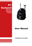
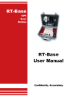
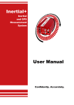
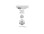
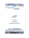
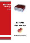
RT-XLAN High performance WLAN radio unit User Manual Confidently. Accurately. Legal Notice Information furnished is believed to be accurate and reliable. However, Oxford Technical Solutions Limited assumes no responsibility for the consequences of use of such information nor for any infringement of patents or other rights of third parties which may result from its use. No license is granted by implication or otherwise under any patent or patent rights of Oxford Technical Solutions Limited. Specifications mentioned in this publication are subject to change without notice and do not represent a commitment on the part of Oxford Technical Solutions Limited. This publication supersedes and replaces all information previously supplied. Oxford Technical Solutions Limited products are not authorised for use as critical components in life support devices or systems without express written approval of Oxford Technical Solutions Limited. All brand names are trademarks of their respective holders. Copyright Notice © Copyright 2014, Oxford Technical Solutions. Revision Document Revision: 140610 (See Revision History for detailed information). Contact Details Oxford Technical Solutions Limited 77 Heyford Park Upper Heyford Oxfordshire OX25 5HD England Tel: +44 (0) 1869 238 015 Fax: +44 (0) 1869 238 016 http://www.oxts.com mailto:[email protected] 2 Oxford Technical Solutions RT-XLAN User Manual Table of contents Introduction 4 Features 4 Models 4 Scope of delivery 5 Warranty 6 Specification 7 Installation 8 Mounting to the vehicle Wiring 8 10 Configuration 11 Operation 12 Checking the communication link Using the RT-XLAN with a standard RT-Range system or direct to RT 12 13 Connections 13 Vehicle wiring options using the RT-XLAN Y cable converter kit 14 Disabling the RT-Range’s wireless LAN 16 Revision history 18 Revision: 140611 3 Introduction The RT-XLAN is a long range radio that extends and improves the communication between vehicles in an RT-Range application. The RT-Range S or original RT-Range is a system that can measure the range from one vehicle to other vehicles in real-time and output its measurements on the CAN bus. It is used for the development of active safety systems in cars. The RT-XLAN is designed for easy connection to the RT-Range S systems. It is also possible to use it with the standard RT-Range systems providing a Y cable converter kit is purchased. The standard RT-Range has a range specified to around 200 m in open environments where there is no interference. The RT-XLAN radios are specifically designed for outdoor use and have a robust, weatherproof design that can operate within a wide temperature range. They also feature a low-loss integrated N-type RF connector replacing the need for radio-to-antenna cable connections that can become a weak link. The RT-XLAN is capable of reliably improving the data communication throughout the range and will also extend the distance between vehicles to around 1km. Features There are several features that make the RT-XLAN ideal for use on vehicles with the RT-Range. These include: Around 1 km robust connection where there is line-of-sight between vehicles. Highly reliable link with very few dropped packets, even at the longer ranges. Superior latency so that it is very rare for packets to take longer than 10ms between vehicles. Powerful suction mounts secure the unit onto vehicles, avoiding the need to strap the radio down. Wide temperature range, making the RT-XLAN suitable for use in winter and summer conditions. Uses standard 2.4GHz radio frequency so can be used license-free in many countries. Models There are two models in the RT-XLAN family. A base unit is needed to set up the network and then multiple client units connect to the base-unit. The base unit acts as an access point and all the clients connect to this access point to share their data. 4 Oxford Technical Solutions RT-XLAN User Manual Scope of delivery The RT-XLAN is supplied with all the parts that are needed for use with the RT-Range. Both the base unit and the client unit come with the same parts. Table 1 lists the parts that are delivered with an RT-XLAN and Figure 1 shows the RT-XLAN and its components. Table 1. Summary of the RT-XLAN components Qty Description 1 RT-XLAN WLAN unit (either base or client) 1 2.4GHz antenna 1 Base-to-antenna extension pole 1 Antenna L bracket 1 Pump cup suction vehicle mount 1 110-00274-301 PoE Ethernet to M12 cable 1 RT-XLAN user manual The difference between a base unit and a client unit can be identified by a sticker on the side. The IP address is also shown. Figure 1. RT-XLAN components Revision: 140611 5 Warranty Oxford Technical Solutions Limited warrants the RT-XLAN to be free of defects in materials and workmanship, subject to the conditions set forth below, for a period of one year from the Date of Sale. ‘Date of Sale’ shall mean the date of the Oxford Technical Solutions Limited invoice issued on delivery of the product. The responsibility of Oxford Technical Solutions Limited in respect of this warranty is limited solely to product replacement or product repair at an authorised location only. Determination of replacement or repair will be made by Oxford Technical Solutions Limited personnel or by personnel expressly authorised by Oxford Technical Solutions Limited for this purpose. In no event will Oxford Technical Solutions Limited be liable for any indirect, incidental, special or consequential damages whether through tort, contract or otherwise. This warranty is expressly in lieu of all other warranties, expressed or implied, including without limitation the implied warranties of merchantability or fitness for a particular purpose. The foregoing states the entire liability of Oxford Technical Solutions Limited with respect to the products herein. 6 Oxford Technical Solutions RT-XLAN User Manual Specification The specifications for the RT-XLAN are shown in Table 2. Table 2. Specifications Parameter Voltage Power Power method Operating temperature Wireless LAN radio range Value up to 24 V ~7 W Passive Power over Ethernet -40 C to +80 C 1 km line-of-sight Wireless LAN delay <10 ms RMS Networking interface 1 X 10/100 BASE-TX Approvals FCC Part 15.247, IC RS210 RoHS compliance YES Operating humidity 5 to 95 % condensing Shock and vibration ETSI300-019-1.4 Dimensions (RT-XLAN unit, antenna and mount) 52.5 cm x 15 cm Ø Dimensions (RT-XLAN unit, including antenna) 37.2 cm x 3.7 cm Ø Weight (RT-XLAN and antenna) ~0.24 kg Weight (total including mount) ~1.08 kg Revision: 140611 7 Installation The installation here assumes that the RT-Range and RT systems have been installed in the vehicle already according to the instructions in their manuals. The installation here covers the RT-XLAN and how to attach it to the vehicle and to the RT-Range S or RTRange. For any installation it is essential to have one RT-XLAN base unit. This would normally be in the hunter vehicle but it can be in any vehicle. One or more RT-XLAN client units can be installed in other vehicles; normally these would be installed in the target vehicles. In environments where more than one RT-Range is being used the RT-XLAN bases will interfere with each other. It is essential to only have one RT-XLAN base unit at any one location. When more than one RT-Range system is being used at the same location and two RT-XLAN bases are needed then contact OxTS support for further help. Mounting to the vehicle The base of the RT-XLAN is a pump cup suction mount that can be attached to any flat non-porous surface such as glass or bodywork. This surface can either be metallic or non-metallic and makes it ideal for a wide variety of vehicle mounting options. Please refer to the drawings in Error! Reference source not found. which show the mounting and removal process. To attach the device to the vehicle: 1. Wipe the mounting surface on the vehicle to ensure it is free from scratches, dust or dirt 2. Remove the plastic protection plate at the bottom of the cup 3. Wipe the base of the suction pad to ensure that it is thoroughly clean 4. Place the suction pad firmly onto the surface 5. Repeatedly press the blue button until the red line disappears into the blue housing Please note: It is wise to regularly check that the red line does not re-appear. If it does, repeatedly press it again a few times until it disappears To release: 1. Hold the RT-XLAN tight with one hand 8 Oxford Technical Solutions RT-XLAN User Manual 2. With the other hand, lift the black tab on the side of the base to firmly break the seal then carefully pull the device away from the vehicle Note: Care should be exercised when removing the device, there may still be a strong vacuum seal holding it to the surface The plastic protection plate should be retained and replaced on the cup when not in use to protect the surface from damage. Figure 2. Attaching and removing the pump cup NOTE: When removing the pump cup from the vehicle, please take extra care to fully break the seal on the base using the tab before attempting to pull the device away. A number of mounting options are available, some of which are shown in Figure 3. Figure 3. Mounting options The pole for the antenna can be fixed either vertically or horizontally to the base and can be adjusted to suit the vehicle and environment. By adjusting the mounting location and antenna angle it may be possible to improve the signal strength of the vehicle to vehicle communication. Revision: 140611 9 Wiring Wiring of the RT-XLAN to the RT-Range S system could not be easier. Simply connect the 110-00274-301 PoE Ethernet to M12 cable from the RT-XLAN to the dedicated socket on the front of the RT-Range S as shown in Figure 4. This dedicated socket powers up the RT-XLAN as well as handling the Ethernet link. Figure 4. Wiring connections to the RT-Range S system Note: Connections to the standard RT-Range system are described on page 13 of this manual Although the RT-XLAN is weather resistant, we strongly recommend that the N-Type connector from the device to the antenna is covered with self-amalgamating tape to help protect it from moisture. When using the RT-XLAN with a standard RT-Range system or standalone with just the RT, it will be necessary to use the Y cable converter kit (ordered separately). More information about this can be found on page 13 of this manual. 10 Oxford Technical Solutions RT-XLAN User Manual Configuration There are no user configuration options on the RT-XLAN. However, it is important to make sure that each unit is compatible with the other units in the environment. There are several items to consider. Each RT-XLAN will have a label showing its configuration. The RT-XLAN labelled “Base” should be used on the Hunter vehicle. The RT-XLAN labelled “Client” should be used on the Target vehicle. There cannot be two RT-XLAN base units in the same environment. There must be one RT-XLAN base unit. The RT-XLAN client units will not communicate with each other unless there is a base present. Each RT-XLAN has an IP address. All the units being used must have different IP addresses. Normally the IP address will be in the range from 195.0.0.170 to 195.0.0.175. It is possible to order different IP addresses from OxTS. This IP address range should not conflict with the recommended IP addresses with other OxTS equipment. The RT-XLAN will be configured for use in a specific country. Different licensing laws require different frequencies to be used in different countries. RTXLAN units from one country cannot be used automatically with RT-XLAN units from another country. It is possible to change the configuration in the field but it is necessary to contact OxTS support for information on how to do this. If any configuration is changed then make sure the stickers on the outside of the RT-XLAN are changed to reflect the configuration changes made. Revision: 140611 11 Operation Once everything is connected the RT-Range can be powered up. The RT-XLAN should work automatically and the RT-Range can be used as normal. LED indicators Found on the side of the RT-XLAN are a series of LEDs. These provide a quick indication of the status of the RT-XLAN without the need for any software. The meanings of these LEDs are shown in Table 3. Table 3. LED indicators LED Label Description Power Power on <···> Link established Shows the strength of the signal across four LEDs The signal strength indicator is a very useful tool for quickly checking the vehiclevehicle signal strength before attaching a PC to the RT-Range system. Checking the communication link It is possible to check that the communication link is working and there are several ways to do this. It should be possible to “ping” the IP address of the RT-XLAN. This can be pinged first on the Ethernet side (i.e. without any wireless communication) and then on the remote side (i.e. through one RT-XLAN to another). If the RT-XLAN is working then packets from RT systems should be visible from any “node”. Enginuity can be used to receive the packets. The LED indicators on the RT-XLAN will provide a quick indication of a communication link and the strength of the signal - as shown in Table 3. 12 Oxford Technical Solutions RT-XLAN User Manual Using the RT-XLAN with a standard RT-Range system or direct to RT Connections If the RT-XLAN is to be used with the standard RT-Range Hunter or Target system, or in a target vehicle without the RT-Range Target, then it will be necessary to supply power and Ethernet to the RT-XLAN via the Y cable converter kit (ordered separately). The kit contains two cables-14C0147A (Y cable) and 14C0149A (cigar plug adapter). Drawings of these cables are shown in Figure 5 and Figure 6. To use the Y converter cable with the RT-XLAN it must first be coupled to the 11000274-301 PoE Ethernet to M12 cable (supplied with the RT-XLAN) to complete the solution. Do not be tempted to extend the Ethernet cable to the RT-XLAN as this may result in damage if the connections are crossed over. Figure 5. Y cable drawing 14C0147A Figure 6. Cigar plug to M12 4 Pole Male pin 14C0149A Revision: 140611 13 For alternative cabling solutions, the pin connections for the 14C0147A and 14C0149A cables are given in Table 4 and Table 5. Table 4. PoE cable connections 14C0147A Signal Name Wire Colour J1 J2 J3 Tx+ Green/White 1 3 N/A Tx- Green 2 6 N/A Rx+ Orange/White 3 1 N/A Supply Brown & White 4 N/A 1&2 Rx+ Orange 6 2 N/A Supply Return Blue & Black 7 N/A 3&4 Table 5. Cigar plug to M12 4 Pole Male pin 14C0149A Signal Name Wire Colour J1 J2 Supply Brown 1 Centre Core Supply White 2 Centre Core Supply Return Blue 3 Outer Contacts Supply Return Black 4 Outer Contacts Vehicle wiring options using the RT-XLAN Y cable converter kit To use the RT-XLAN with standard RT-Range systems, connect the (J2) RJ45 plug on the Y cable to a spare Ethernet socket located on the front of the RT-Range hunter or target unit and the (J3) M12 plug of the Y cable to the spare power output of the RTRange hunter or target unit as shown in Figure 7. It is also possible to use just the RT-XLAN connected directly to the RT and completely avoid using the RT-Range target unit where no other connectivity is required in the target vehicle. To do this, connect the cigar plug cable (14C0149A) to the (J3) M12 plug of the Y cable then connect the cigar plug to the power source. Connect (J2) RJ45 plug of the Y cable to the Ethernet on the RT User Cable (J6) using the cross-coupler supplied with the RT3000 & RT4000 or directly to the RT2002 as shown in Figure 8. 14 Oxford Technical Solutions RT-XLAN User Manual Figure 7. Wiring diagram for RT-Range with an RT-XLAN Note: connections not relevant to the RT-XLAN are not shown in this diagram. The RT connections shown are for an RT3000 / RT4000 unit. With an RT2002, the RT-Range connections are made directly to the front panel of the RT2002 instead of through the 14C0038A user cable. Figure 8. Wiring diagram for RT2002/RT3000/RT4000 without RT-Range target Note: connections not relevant to the RT-XLAN are not shown in this diagram. The RT connections shown are for an RT3000 / RT4000 unit. With an RT2002, the RT-Range connections are made directly to the front panel of the RT2002 instead of through the 14C0038A user cable. Revision: 140611 15 The wireless LAN antenna on the RT-Range should be removed. It may be necessary to disable the wireless LAN in the RT-Range to avoid Ethernet conflicts. During tests at OxTS it has been possible to run both the RT-Range wireless LAN and the RTXLAN at the same time but this cannot be guaranteed. See the next section on Error! Not a valid bookmark self-reference.. Disabling the RT-Range’s wireless LAN It has not been necessary to disable the wireless LAN in the old style RT-Range cases in order to use the RT-XLAN. However, there may be times when the internal wireless LAN will conflict with the RT-XLAN. If this happens then the internal wireless LAN in the RT-Range should be disabled. If the internal RT-Range wireless LAN is disabled then clearly label the outside of the box so it is clear that it has been disabled. It is very difficult to diagnose a problem with the wireless LAN so clear marking is essential. In order to disable the wireless LAN in the RT-Range it is necessary to disassemble it. The instructions for disassembling both the RT-Range Hunter and the RT-Range Target are the same. These instructions can also be used to enable the wireless LAN if the RTXLAN is no longer being used. To remove the front panel from the RT-Range Hunter carefully undo the 4 screws on the front panel. These usually require a 2mm metric Allen (hex) key; some RT-Range systems have been supplied with screws that require a 2.5mm Allen key. Figure 9. Removing the front panel screws on the RT-Range Hunter Do not remove the front panel completely; just raise it high enough to gain access to the internal wireless LAN as shown in Figure 9. Be aware of the metal strengthening bars at the top and bottom; these are loose and will drop off very easily. If they do, ensure they are back in place before doing the panel back up and ensure that the screw holes are lined up accurately. 16 Oxford Technical Solutions RT-XLAN User Manual Once the panel is undone, the back of the WLAN unit can be seen. This is shown in Figure 10. Remove the power jack plug. Cover the jack plug with insulation tape so that it does not short against anything internally. Secure the jack plug with tape so that it cannot flap about inside the RT-Range Hunter. The internal wireless LAN is now disabled. Figure 10. Disconnecting the power jack Note that it is not necessary to use the RT-Range Target in some applications. The RT-Range Target contains a wireless LAN and an Ethernet switch and the serial output/input connections. If the Ethernet switch or serial connections are not needed, or if another switch is available, then the RT-XLAN can be used without the RT-Range Target. Revision: 140611 17 Revision history Table 6. Revision history Revision Comments 131101 Initial version 140611 Revisions for RT-Range S and new cables 18 Oxford Technical Solutions