1
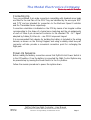
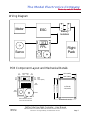
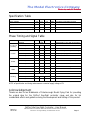
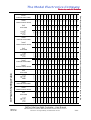
FlytProf-Lite
Free-Flight Controller
User Manual
The Model Electronics Company
Electronics made for Modellers
Table of Contents
Heading
Page
Table of Contents
IFC
Introduction
1
Flight Mode
2
Glide Phase Timing
2
In-Flight Safety Features
3
Programming Mode
Default Settings
3
4
The Flight Control System
5
Power Supply
5
Electronic Speed Controller
5
De-Thermaliser Servo
5
Connecting Up
6
Power-Up Sequence
6
Wiring Diagram
7
PCB Component Layout and Mechanical Details
7
Specification Table
8
Phase Timing and Signal Table
8
Acknowledgement
8
DIP Switch Settings Table
IBC
FlytProf-Lite Free Flight Controller - User Manual
Issue 3.0
16-01-08
The information contained within this manual is believed to be correct.
However no responsibility is assumed for its use.
IFC
The Model Electronics Company
Electronics made for Modellers
Introduction
FlytProf-Lite is a small, self-contained and simple-to-operate microprocessor
based unit designed to provide electric free-flight modellers with a means of
controlling an aircraft's flight profile. It operates as the central, controlling element
of a Flight Control System by stepping through a pre-programmed sequence of
timed Phases and, for each Phase, provides two standard R/C servo drive
outputs.
The first of these is intended to drive an external motor speed controller [ESC]
to provide power control and the other, connected to a servo, provides the 'dethermaliser' [DTS] function.
FlytProf-Lite enables simple flight profiles to be implemented by providing 4
active Phases known as Launch, Power, Glide and Landing and two of these, the
Power and Glide Phases, have user-programmable parameters – see the Phase
Timing and Signal Table section.
The Power Phase has programmable ESC drive and Duration parameters and a
fixed DTS drive while the Glide Phase provides fixed ESC and DTS drives but
offers a programmable Duration. Setting of the three programmable parameters
is achieved by means of an on-board 6-way DIP switch and timed push-button
presses and, once entered, the flight profile program is stored in non-volatile
memory [NVM] ready for immediate use on the flying field.
There is no practical limit to the number of times the parameters may be reprogrammed.
FlytProf-Lite has two operating modes, known as Flight and Programming.
Selection of the operating mode and control of the unit in each mode is
performed by the board mounted push-button with acoustic feedback provided
by the on-board buzzer.
FlytProf-Lite may be identified within the FlytProf family by the black push-button.
FlytProf-Lite Free Flight Controller - User Manual
Issue 3.0
16-01-08
The information contained within this manual is believed to be correct.
However no responsibility is assumed for its use.
Page 1
The Model Electronics Company
Electronics made for Modellers
Flight Mode
Powering-up FlytProf-Lite without pressing the push-button causes it to enter
Flight Mode in a Pre-Launch state. In this condition the ESC drive is set to
1.00ms – in order to 'arm' the speed controller – and the DTS drive is set to its
in-flight position of 1.00ms. The buzzer emits a continuous sound indicating that
the unit is waiting for the push-button to be pressed.
Momentarily pressing the push-button causes FlytProf-Lite to enter the Launch
Phase in which it ramps up the motor speed to its programmed value. Once the
motor has reached its programmed speed FlytProf-Lite automatically enters the
Power Phase and begins timing its Duration. Short 'ticks' are emitted by the
buzzer at 1-second intervals confirming that the timing system is operating
correctly.
On expiry of the timer, FlytProf-Lite enters the Glide Phase in which the motor
is shut down and the duration timer is restarted with the programmed value. At
the end of the Glide Phase the unit enters the Landing Phase and activates the
DTS to bring the model down.
On recovery of the model the buzzer will be heard emitting 1-second ‘ticks’
indicating that the flight sequence completed normally.
To accommodate flights that end prior to the programmed duration pressing the
push-button until a continuous sound is heard, and then releasing it, at any time
during either the Glide or Landing phases cancels the current flight timing
sequence and places FlytProf-Lite back into its Pre-Launch condition ready to
enter a new Launch Phase.
This permits a new sequence to be started without the need to cycle the power.
Glide Phase Timing
Although FlytProf-Lite’s DTS output is primarily intended for controlling a dethermaliser servo it may be re-assigned to any control-surface trimming function
and, to provide timing flexibility for these alternative uses, the Glide Phase
Duration is programmable with two resolutions.
Settings in the first section of the DIP Switch Settings Table offer timings of
FlytProf-Lite Free Flight Controller - User Manual
Issue 3.0
16-01-08
The information contained within this manual is believed to be correct.
However no responsibility is assumed for its use.
Page 2
The Model Electronics Company
Electronics made for Modellers
between 1 and 15 seconds in 1-second steps while the remaining 3 sections
permit Glide Duration values from 20 seconds to 255 seconds (4.25 minutes) in
5-second increments to be programmed.
NOTE: contrary to typical mechanical timers in which all timers are started at launch, FlytProf-Lite
starts timing the Glide Phase at the expiry of the Power Phase. Thus, for the normal
application, a setting of 10 seconds for both phases results in a flight lasting for 20 seconds.
In-Flight Safety Features
FlytProf-Lite has two safety features built in to its program. The first of these is a
battery voltage detection system which, in the event of a significant dip in supply
voltage during a flight, causes the unit to re-enter its Pre-Launch condition
shutting down the motor .
On recovering the model the activation of this mechanism may be determined
by a continuous tone being emitted from the buzzer rather than the normal 1second 'ticks'.
The second safety feature detects a stuck pushbutton. At the end of the Power
Phase the pushbutton is checked and if it is found to be 'pressed' the unit
immediately enters a Safety Phase shutting down the motor and setting the DTS
output to bring the model down.
The buzzer issues a buzzing sound to indicate that this mechanism has been
triggered and the power must be switched off to cancel this condition.
Programming Mode
Holding the push-button pressed while powering-up causes FlytProf-Lite to enter
Programming Mode, which it confirms by emitting 3 short 'beeps' from the
buzzer. Releasing the push-button causes the buzzer to emit a continuous sound
indicating that the unit is waiting for a button press. It is in this 'idle' state that the
DIP switch may be set to determine the value of the parameter to be
programmed – see the DIP Switch Settings Table.
Once the DIP switch has been set, the programming sequence is started by
FlytProf-Lite Free Flight Controller - User Manual
Issue 3.0
16-01-08
The information contained within this manual is believed to be correct.
However no responsibility is assumed for its use.
Page 3
The Model Electronics Company
Electronics made for Modellers
pressing and holding the push-button. This immediately silences the buzzer,
which then starts emitting a sequence of three 1-second long 'silences' followed
by 1-second long 'beeps' – indicating the three programming slots. Releasing the
button during one of the three 1-second 'beeps' determines which of the
parameters is to be programmed:1. Motor Speed Pulse Width
2. Power Phase Duration
3. Glide Phase Duration
in ms
in seconds
in seconds – see DIP Switch Settings table
Confirmation of programming is indicated by the emission of two short 'beeps'
and FlytProf-Lite then returns to its idle state, with the buzzer sounding
continuously, waiting for a push-button press to initiate programming of the next
parameter.
Any, or all, of the parameters may be programmed as many times as required
during each programming session.
NOTE: the programming sequence is cyclic and so, if the intended programming slot is missed, then
simply keeping the push-button pressed until the appropriate slot in the next cycle will
program the unit correctly. The start of a new programming cycle is indicated by an
extended period of silence.
To exit Programming Mode switch off the power when FlytProf-Lite is in its idle
state and emitting a continuous sound.
Default Settings
FlytProf-Lite is shipped with a set of default parameter values as indicated by the
shaded area of the DIP Switch Settings Table. These provide a modest power
setting and short Phase durations and are suitable for initial land-based testing.
They may be restored, as a set, at any time by setting the DIP switch to the allzeros code and programming any one of the 3 Phase Parameters. Confirmation
that the default values have been successfully restored is indicated by the buzzer
emitting 4 short ‘beeps’ rather than the usual two.
FlytProf-Lite Free Flight Controller - User Manual
Issue 3.0
16-01-08
The information contained within this manual is believed to be correct.
However no responsibility is assumed for its use.
Page 4
The Model Electronics Company
Electronics made for Modellers
The Flight Control System
Power Supply
The Flight Control System is powered by the Battery Eliminator Circuit [BEC]
within the ESC – see the Specification Table section. Using this method the flightpack voltage is reduced within the ESC to about 5V and is typically provided on
the central pin of its servo-lead connector.
The FlytProf-Lite PCB is wired to route this supply via the Power Switch to the
on-board electronics and to the central pin of the DTS connector. Thus the
flight-pack provides power for the entire Flight Control System saving the weight
and bulk of a separate pack.
NOTE: in order to prevent possible erratic operation in flight, it is important to verify, by means of
ground-based testing, that the BEC can provide enough current to drive the DT Servo
under worst case battery and load conditions.
Electronic Speed Controller
The choice of ESC is not critical and may be selected from the available range
based on the preferred motor type, brushless or otherwise, and power rating. It
must be capable of accepting the standard R/C servo control signal of a 20ms
frame containing a 1-2ms positive-going pulse and interpreting a pulse width of
about 1.00ms as zero power and a pulse width of about 2.00ms as full power.
Additionally, it must be verified that its on-board BEC can provide enough
current to drive the chosen DT Servo and that it will operate successfully from
the desired flight-pack voltage – some ESCs place a limit on the maximum
number of flight-pack cells if their on-board BEC is to be used.
De-Thermaliser Servo
The selection of DT Servo is also not critical and should be based on the weight
and power requirement of the model. During a typical flight the DT Servo is idle
for most of the time, operating for only a second or so toward the end to bring
the model down, and thus its overall power requirements are very low.
However, it is at the end of a flight that the battery pack is at its lowest charge
and so selecting a low-current servo will reduce the risk of control system failure
due to battery voltage droop.
FlytProf-Lite Free Flight Controller - User Manual
Issue 3.0
16-01-08
The information contained within this manual is believed to be correct.
However no responsibility is assumed for its use.
Page 5
The Model Electronics Company
Electronics made for Modellers
Connecting Up
Two non-polarised, 3-pin male connectors compatible with standard servo leads
are fitted to the rear face of the PCB. They are identified by the acronyms ‘ESC’
and ‘DTS’ and are intended for connection to the Electronic Speed Controller
and De-Thermaliser Servo respectively.
Connection orientation is indicated on the PCB by means of an irregular outline
corresponding to the shape of a typical servo lead plug and the pin assignments
of each of these 3-pin connectors conforms to the standard "0V : 5V : Signal"
adopted by Futaba, JR, Hitec etc. – see PCB Component Layout.
It is recommended that a device for isolating the battery is included in the wiring
harness, as shown on the Wiring Diagram, and using a suitably rated two-part
connector will also provide a convenient connection point for recharging the
flight-pack.
Power-Up Sequence
Before making the battery connection ensure that FlytProf-Lite’s Power Switch is
in the Off position. Once the battery is connected the Flight Control System may
be powered-up by moving the Power Switch to the On position.
Follow the reverse procedure to power the system down.
FlytProf-Lite Free Flight Controller - User Manual
Issue 3.0
16-01-08
The information contained within this manual is believed to be correct.
However no responsibility is assumed for its use.
Page 6
The Model Electronics Company
Electronics made for Modellers
Wiring Diagram
Motor
+
-
ESC
+
-
Battery
Isolation
ESC
DTS
FPL
Flight
Pack
Servo
PCB Component Layout and Mechanical Details
To
DTS
Power Switch
OFF
ON
24.13 (0.950)
To
ESC
20.95 (0.825)
0V - Black
5V - Red
SIG - Yellow (White)
0V
5V
SIG
0
PushButton
29.21 (1.150)
DIP
Switch
32.38 (1.275)
1
4 off Holes
1.10 (0.043)
Buzzer
NOTE
ESC and DTS Connections
are on the rear of the PCB
Dimensions in mm (in)
FlytProf-Lite Free Flight Controller - User Manual
Issue 3.0
16-01-08
The information contained within this manual is believed to be correct.
However no responsibility is assumed for its use.
Page 7
The Model Electronics Company
Electronics made for Modellers
Specification Table
Parameter
Min
Typ
Max
Units Comment
Supply Voltage
4.5
5.0
6.0
Volts
1.5
mA
Supply Current
ESC & DT Servo Pulse Width Range
1.00
2.00
ms
ESC & DT Servo Pulse Amplitude
4.0
5.0
Volts
Provided by ESC BEC function
No external loads
No external loads
Phase Timing and Signal Table
Phase
Parameter
Min
Duration
Typ
Max
Units Comment
Determined by user with push-button
N/A
Pre-Launch ESC Drive pulse width
(or Idle)
DT Servo pulse width
0.98
1.00
1.02
ms
Fixed
0.98
1.00
1.02
ms
Fixed
Duration
0.02
1.28
sec
Determined by Motor Speed setting
ESC Drive pulse width
1.00
2.00
ms
Ramps up to programmed value
DT Servo pulse width
0.98
1.02
ms
Fixed
1
63
sec
Programmable in 1 second steps
ESC Drive pulse width
1.04
1.97
ms
Programmable in 63 equal steps
DT Servo pulse width
0.98
1.02
ms
Fixed
255
sec
See DIP Switch Settings table
Launch
Duration
Power
Duration
Glide
1.00
1
ESC Drive pulse width
0.98
1.00
1.02
ms
Fixed
DT Servo pulse width
0.98
1.00
1.02
ms
Fixed
Duration
Landing
1.00
N/A
ESC Drive pulse width
0.98
1.00
1.02
ms
Fixed
DT Servo pulse width
1.98
2.00
2.02
ms
Fixed
NOTE: all specification and timing values assume a nominal supply voltage of 5V.
Acknowledgement
Thanks are due to Ian Middlemiss of Peterborough Model Flying Club for providing
the original idea for the FlytProf free-flight controller range and also for his
considerable efforts and guidance during the development and testing of this product.
FlytProf-Lite Free Flight Controller - User Manual
Issue 3.0
16-01-08
The information contained within this manual is believed to be correct.
However no responsibility is assumed for its use.
Page 8
1.07
1.09
1.10
1.12
1.13
1.15
1.16
1.18
1.19
1.21
1.22
1.24
1.25
110000
001000
101000
011000
111000
000100
100100
010100
110100
001100
The information contained within this manual is believed to be correct.
However no responsibility is assumed for its use.
101100
011100
111100
FlytProf-Lite Free Flight Controller - User Manual
IBC
15
14
13
12
11
10
9
8
7
6
5
4
3
2
111110
011110
101110
001110
110110
010110
100110
000110
111010
011010
101010
001010
110010
010010
ESC Drive
(ms)
1.49
1.48
1.46
1.45
1.43
1.42
1.40
1.39
1.37
1.36
1.34
1.33
1.31
1.30
1.28
1.27
Power Phase Duration
(secs)
31
30
29
28
27
26
25
24
23
22
21
20
19
18
17
16
Glide Phase Duration
(secs)
95
90
85
80
75
70
65
60
55
50
45
40
35
30
25
20
111101
011101
101101
001101
110101
010101
100101
000101
111001
011001
101001
001001
110001
010001
100001
000001
123456
DIP
Switch
Setting
ESC Drive
(ms)
1.73
1.72
1.70
1.69
1.67
1.66
1.64
1.63
1.61
1.60
1.58
1.57
1.55
1.54
1.52
1.51
Power Phase Duration
(secs)
47
46
45
44
43
42
41
40
39
38
37
36
35
34
33
32
Glide Phase Duration
(secs)
175
170
165
160
155
150
145
140
135
130
125
120
115
110
105
100
111111
011111
101111
001111
110111
010111
100111
000111
111011
011011
101011
001011
110011
010011
100011
000011
123456
DIP
Switch
Setting
ESC Drive
(ms)
1.97
1.96
1.94
1.93
1.91
1.90
1.88
1.87
1.85
1.84
1.82
1.81
1.79
1.78
1.76
1.75
Power Phase Duration
(secs)
63
62
61
60
59
58
57
56
55
54
53
52
51
50
49
48
255
250
245
240
235
230
225
220
215
210
205
200
195
190
185
180
Glide Phase Duration
(secs)
Key: the ‘0s’ and ‘1s’ in the DIP Switch Setting columns represent the individual switches placed in the Off and On positions respectively
15
14
13
12
11
10
9
8
7
6
5
4
3
2
100010
1.06
1
010000
1
1.04
100000
15
000010
10
1.50
000000
DIP
Switch
Setting
123456
Power Phase Duration
(secs)
123456
ESC Drive
(ms)
Issue 3.0
16-01-08
DIP
Switch
Setting
Glide Phase Duration
(secs)
DIP Switch Settings Table
The Model Electronics Company
Electronics made for Modellers
The Model Electronics Company
68 Kentsford Road
Kents Bank
Grange-over-Sands
Cumbria
LA11 7BB
United Kingdom
http://www.omegaco.demon.co.uk/mechome.htm