1
IN
■
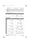
CASE OF BOTTOM PIPING
1. EXTERIOR
Be sure to foresee enough space for brazing and piping
work under the unit.
For HP/LP gas pipes only
For L dimension of HP/LP gas pipes 1~3, dimension B of the
field supplied angled joint as in table 27 on page 12 has been
taken into account. Further, connection of gas pipes and the
field supplied joints for same diameter are of the type without
stoppers. If dimension B of the angled joint you use is different
from that dimension B and/or if the joints for same diameter
pipes have stopppers, adjust the L dimension of HP/LP gas
pipes 1~3 accordingly.
Table 36
Pipe 1
L (mm)
Outdoor unit
Pipe 2
L (mm)
Pipe 3
L (mm)
(field supply) (field supply) (field supply)
34~44 Hp
155
86
94
L
46+48 Hp
119
110
82
Cutting suction gas reducer (1), (2) and (3) and HP/LP
gas reducer (2) and (3)
Suction gas
reducer (1)
Unit A
detail A
Suction gas
reducer (1)
Unit B
1
4
34 Hp
3
3
85
4
2
5
Suction gas
reducer (2)
107
168
310
6
1
Liquid pipe
3
Suction gas pipe
2
HP/LP gas pipe
4
Equalizer pipe
2. INSTALLATION OF
HP/LP GAS PIPES
Suction gas
reducer (3)
2
Connection to suction gas
joint (1)
3
Cutting position
4
Connection to suction gas
accessory pipe 2
5
Connection to suction gas
joint (2)
6
Connection to suction gas pipe
(field supply)
7
Connection to suction gas
joint (2)
8
No cutting for 34~40 Hp
6
8
34~38+42 Hp
42~48 Hp
3
3
40+44~48 Hp
SUCTION GAS AND
Connection to suction gas
accessory pipe 1
36~48 Hp
49
A
109
34~48 Hp
1
7
7
Cutting the field supplied and unit suppled gas pipes
■
For suction gas pipes only
For L dimension of suction gas pipe 1, dimension B of the field
supplied angled joint as in table 25 on page 11 has been taken
into account. Further, connection of gas pipes and the field
supplied straight size joints are of the type without stoppers. If
dimension B of the angled joint you use is different from that
dimension B and/or if the straight size joints have stopppers,
adjust the L dimension of suction gas pipe 1 accordingly.
HP/LP gas
reducer (2)
Unit A
1
HP/LP gas
reducer (2)
Unit B
4
34~48 Hp
HP/LP gas
reducer (3)
6
5
42~48 Hp
3
3
2
2
3
5
38~42 Hp
1
Connection to HP/LP gas
pipe 1
2
Connection to HP/LP gas
reducer (1)
3
Cutting position
4
Connection to HP/LP gas
pipe 2
5
No cutting for 34~40 Hp
6
Connection to HP/LP gas
pipe (field supply)
7
Connection to HP/LP gas
joint (2)
8
No cutting for 34+36 Hp
44~48 Hp
Table 35 (for outdoor unit C)
Suction gas accessory
pipe (3)
(delivered with the unit)
Outdoor unit
7
Suction gas pipe 1
(field supply)
B (mm)
L (mm)
34~38 Hp
0(b)
137
40~46 Hp
0(b)
48 Hp
41
a
102
L
B
98
a = cutting position
b = no cutting required
BHFQ23P907+1357
Outdoor unit multi connection piping kit
4PW38477-1
Installation manual
16