1
Table of contents:
1. Health & safety precautions:....................................................................................................................... 2
2. Transportation, offloading and storage:.................................................................................................... 2
3. The wastewater purification process:........................................................................................................ 3
4. Tank dimensions: ......................................................................................................................................... 4
5. Tank drawing: ............................................................................................................................................... 4
6. Manhole risers – (deep inverts):.................................................................................................................. 5
7. Installation: ................................................................................................................................................... 5
7.1 Pre –installation inspection: ................................................................................................................
5
7.2 Quick installation guidelines:................................................................................................................. 6
7.3 Detailed installation information: ..........................................................................................................7
7.4 Dry site installation: .............................................................................................................................. 10
7.5 Deeper tank installation & wet site installation:.............................................................................. 11
7.6 Plinth and backfill specifications: .........................................................................................................12
8. Plumbing the system:..................................................................................................................................14
9. Finishing the garden to ground level:.......................................................................................................15
10. Maintenance:............................................................................................................................................... 16
11. Operating conditions:..................................................................................................................................17
It is important to read the full technical and installation guide prior to installation. This document should be
retained for the lifetime of the product and in the event of change of ownership be transferred to the new
owner.
Precaution
Prior to installation, please consider finished garden level when installing the system. If you envisage that a
manhole riser/extension may be required to ensure manhole lid remains above finished ground level, the system
must be installed with the appropriate excavation foundation and backfill to accommodate the riser. Please refer to
page 5 for manhole riser details.
1
TTM T202 Rev02 12 Mar 14
1. Health and safety precautions:
As safety and security are of vital importance in septic tank installation, the following aspects are critical.
•
Ensure that all the information contained in this manual is adhered to at all times
•
When working with machinery / electrical equipment, proximity of water shall be noted.
•
There is potential danger when de-sludging and therefore this shall never be done alone.
•
Never enter a tank unless qualified to do so.
•
Naked flames shall not be used in the vicinity of the tank due to the danger of combustion.
•
The manhole cover shall never be left off an unattended tank.
•
Protective clothing / gloves shall be worn at all times. Always remove contaminated clothing and protective
equipment after working with septic tank.
•
Wash hands and face prior to eating, drinking or smoking.
•
A second person shall be present when carrying out maintenance.
•
A sampling box shall be constructed to facilitate sampling and inspection without placing personnel at risk.
•
Great care shall be taken when handling sludge.
•
Always lock the cover of the system when maintenance is completed.
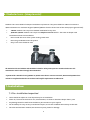
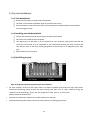
2. Transportation. Offloading and storage:
1. Tanks must be held down during transportation using nylon straps, do not use cables or chains to secure
tanks. Do not over tighten straps to cause deformation of the tank shell
2. Always set the tank(s) on flat smooth ground free from debris etc. To prevent movement, tanks may need to be
tied down.
3. Tanks are best lifted by crane or suitable lifting equipment and webbing lifting straps – do not use chains
or wire ropes in contact with the tank. Ensure tank is empty when lifting.
4. Move tanks only by lifting and setting, do not drag or roll
5. Do not drop or roll tanks from truck/trailor
2
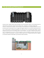
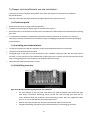
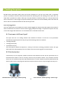
3. The wastewater purification process:
3. The wastewater purification process:
The septic tank is another product within the range of Tricel environmental solutions. The Tricel septic tank is an
ideal solution for wastewater treatment where sufficient land is available for an adequate drainage field.
The tank is divided into two chambers, sized sufficiently to hold wastewater for an adequate amount of time for
the solids to drop to the bottom to form a sludge and the lighter material to rise to the top of the liquid to form a
scum. A certain amount of anaerobic breakdown occurs within the tank. The remaining liquid effluent is passed
through the outlet pipe into the drainage system for final treatment. The liquid is dispersed evenly within a
series of drainage pipes into the soil. The micro organisms in the soil breakdown any organic matter left in the
effluent. As most of the treatment is carried out in the percolation area, it is important that the land is adequate
for sufficient treatment of wastewater to prevent harm to the environment.
3
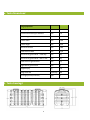
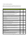
4. Tank dimensions:
4. Tank dimensions:
Design population
Tank capacity
litre
3080
Nominal inlet/outlet pipe diameter
mm
110
Overall length
mm
2700
Overall width
mm
1190
Overall height
mm
1440
Inlet invert to base
mm
1180
Outlet invert to base
mm
1150
Inlet invert to ground level – tank only
mm
185
Inlet invert to ground level – with 1 riser
mm
365
Outlet invert to ground level
mm
215
Height above ground level
mm
75
Weight empty
kg
119
Design flow rate
litres/day
180
De-sludge period (minimum)
year
1
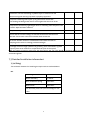
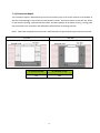
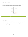
5. Tank drawings:
5. Tank drawing:
4
6. Manhole risers – (deep inverts):
6. Manhole risers – (deep inverts):
Manhole risers are available for deeper installation requirements. They are available in 180mm increments x
400mm diameter to a maximum height of 900mm (960mm from the invert level of the outlet pipe to ground level).
180mm manhole risers require a standard installation for dry sites.
360mm & 540mm manhole risers require a complete concrete backfill – See notes on deeper tank
installation and wet site installation.
Never install the cover of the system under ground level.
Never let groundwater enter the system.
Only Tricel risers should be used.
All manholes lids are lockable and should be locked for safety and to prevent unauthorised access. All
maintenance work is done through these manholes
*Systems with a manhole riser of 360mm or 540mm must have a concrete surround. 360mm and 540mm risers
cannot be retrofitted unless the correct base and backfill requirements are adhered to.
7. Installation:
7.1 Pre –installation inspection:
•
Tanks should be subject to visual inspection prior to installation
•
Check for, fractures to the shell or ribs, de laminations, scratches or abrasions deeper than 1.5mm
•
Any damage should be notified to the delivery driver and/or to your supplier
•
Do not attempt to carry out any un-authorised repairs, as this will invalidate the warranty on the tank
•
Once the tank has been installed, we cannot accept any claims for damage
5
7.2 Quick installation guidelines:
A dry site is one where the water table never rises higher than the base of the Tricel unit. A
wet Site is one where the water table may rise higher than the base of the Tricel unit. The
unit should never be installed where ground water can rise higher than the outlet pipe
Guidelines
Dry Site
All installations must be “Fit for purpose” to suit the on-site conditions, which
will vary from site to site. This is the responsibility of the onsite contractor.
Never roll the tanks. Tanks shall be lifted into position.
The unit should be located as far away from the dwelling as is practically
possible considering topography and pipe work levels. Separation
distances must meet all National and Local regulations
Dig a hole circa 400mm larger than the system in plan.
Remove any soft spots or boulders of significant size from the base or sides
of the excavation
Ground water must be pumped to give a dry excavation and excavation
lined with polythene
Provisions for anchor straps if required should be built into the foundation
A base is then formed using 200mm of concrete/semi dry mix (suitable to
site conditions) and this must be flat and level.
A base is constructed of a 200mm layer of concrete/semi dry mix to suit
site conditions. This must be flat and level.
Ensure gravel/concrete are clean and contains no large materials
Lift tank into position and align as required for connecting pipe work,
access shafts etc.
Ensure that each tank is 100% level, and that inlet/outlets are in the
correct orientations.
Secure anchor straps if required.
Ballast the tank with water.
Mount risers
Commence gravel backfilling in 300mm layers to 100mm over the
tank, ensuring tank and any pipe work is properly supported.
6
Wet Site
Commence concrete backfilling in 300mm layers to 100mm over the
tank, ensuring tank and any pipe work is properly supported.
Complete backfilling with topsoil up to ground level. Ensure that
surrounding finished ground level is never higher than the cover of the
Compaction should be by lightweight rollers or vibratory plate compactor until
“traffic” depth has been achieved
Compact evenly around the riser extensions to reduce risk of distortion.
Ensure that No surface loadings are transferred from the cover direct to
the tank. Cover frame construction should allow movement.
An access chamber should be installed before and after the tank for
sampling and to assist in clearing possible blockages
If sewage consists of high quantities of grease e.g. from a restaurant, a grease
trap may have to be installed on a separate drain prior to the system.
Note: The option of anchor straps may also be used on wet site. This should be designed by an on-site
structural engineer.
7.3 Detailed installation information:
7.3.1 Siting:
The minimum distances for installing the septic tank are outlined below:
UK:
A dwelling
10 metres
Wall or boundary
5 metres
Well, borehole or spring
50 metres
Watercourse
10 metres
The soak away should be 5m from a hedge or tree
roots
7
Ireland:
Tank and percolation area
A dwelling
7 metres
Site boundary
3 metres
Road
4 metres
Well, borehole, watercourse
or spring
Lake
10 metres
50 metres
7.3.2 Control of groundwater:
Tanks must not be subjected to buoyant forces during installation, taking account of ground water
levels and surface water run-off, and their accumulation in the tank pit, even if tanks are anchored.
The excavation area should be adequately drained, to permanently remove ground water from the
proximity of the tank (or tanks). This is critical in order to avoid flotation of the tanks. Incorrectly
installed tanks that are subject to movement, rotation or floatation may become damaged, for which
we cannot accept liability. Water should be removed as much as possible from around the tanks using
piped drains.
7.3.3 Note: water logged sites:
The Tricel System is not suitable to be used in water logged sites, where the ground water may rise above
the outlet level. Please contact the supplier of the system if there are difficulties on site due to
adverse water logging. Adequate drainage is important to improve wet sites, or sites with a high water
table level. It is critical that water is removed from the area surrounding the system to prevent
flotation. Excessive loading caused by site water can harm the system, please consult with the
manufacturer or a qualified engineer if in doubt.
7.3.4 Excavation size:
Suitably sized equipment will be required to excavate the hole and to crane the system into place.
Installation depends on on-site conditions, water, slopes, location etc. Excavation should be planned
with due regard to Health and Safety requirements, and should be either shored or battered back to a
“safe” angle. The excavation should allow a minimum 200mm clearance between the tank and the
excavation wall or face of shoring. Unstable ground with excessive sand, peat swamps etc. may
require larger excavations. The excavation should be maintained dry by pumping or whatever suitable
means.
External dimensions: Dia in meters x Length in meters
Total excavation: {Width + 200mm} x {Length +
200mm} Excavation depth: Allow 200mm for a tank
base/plinth.
8
7.3.5 Excavation depth:
The excavation depth is determined by the inlet and outlet pipe, invert levels relative to the bottom of
the tank, and allowing for the minimum base thickness shown. Dimension details of the tank are shown
on the relevant drawing, supplied with the system. Ground instability at formation level e.g. running sand
may necessitate over-excavation and stabilisation with hardcore or blinding concrete.
NOTE: Check that the depth to the base slab is within the Service Specification requirements for the tank.
Dry Site
Wet Site
“a” minimum in mm
“b” minimum in mm
200
200
9
7.4 Dry site installation:
7.4.1 Tank base/plinth:
Remove any soft spots or large stones and boulders
The base is constructed of a 200mm layer of concrete/semi dry mix.
Ensure that base is level and ensure that correct orientations are determined to accommodate
the incoming pipe work
7.4.2 Installing onto the base/plinth:
Lift the unit carefully into the hole and place on the prepared plinth
The unit must sit dead level on the plinth
The higher pipe on the tanks is to be connected to your upstream (inlet) pipe work and the
lower pipe on the tank is to be connected to you downstream (outlet) pipe work. Connect and
seal the pipe work to the tank, checking alignment to ensure there is an adequate fall for each
pipe.
Mount manhole risers (if used)
7.4.3 Backfilling dry site:
Refer to backfill specification appropriate for site conditions
•
Fill each chamber of the unit with clean water to a depth of 300mm and recheck the pipe work levels.
Commence backfilling evenly around the tank ensuring that there are no voids. Continue filling the
chambers whilst backfilling, ensure that the progressive water level is no more than
300mm above the backfill level.
•
Continue to backfill until material has reached 100mm over the tank.
•
Complete backfilling with topsoil. Ensure lid remain above surrounding ground level.
10
7.5 Deeper tank installation & wet site installation:
A concrete surround is required, where two or more risers are required or where the site conditions
are considered wet.
A wet site is one where the water table may rise higher than the base of the Tricel unit.
7.5.1Tank base/plinth:
•
Remove any soft spots or large stones and boulders.
•
The base is constructed of a 200mm layer of concrete/semi dry mix.
•
Ensure that base is level and ensure that correct orientations are determined to accommodate the incoming
pipe work.
•
It is important to maintain a completely dry excavation until the final pour of concrete is set. It may be
necessary to line the excavation with a continuous layer of 1200gauge polythene to maintain the integrity
of the concrete.
7.5.2 Installing onto the base/plinth:
•
Lift the unit carefully into the hole and place on the prepared plinth before the concrete sets
•
The unit must be dead level on the plinth
•
The higher pipe on the tanks is to be connected to your upstream (inlet) pipe work and the lower pipe on
the tank is to be connected to you downstream (outlet) pipe work. Connect and seal the pipe work to the
tank, checking alignment to ensure there is an adequate fall for each pipe.
•
Mount and seal manhole extensions (if used)
7.5.3 Backfilling a wet site:
Refer to backfill specification appropriate for site conditions
•
Fill each chamber of the unit with clean water to a depth of 300mm and recheck the pipe
work levels. Commence backfilling evenly around the tank ensuring that there are no
voids. Continue filling the chambers whilst backfilling, ensure that the progressive water
level is no more than 300mm above the backfill level.
•
•
Backfill with concrete/semi dry mix until it has reached 100mm over the tank.
Complete backfilling with topsoil. Ensure lid remain above surrounding ground level.
11
7.6 Plinth and backfill specifications:
7.6.1 Concrete backfill specification:
Semi dry concrete 25n grade with a ratio of 4.5 aggregate to 1 cement.
Note: Standard concrete mixes should not be used, where sulphates or similar aggressive chemicals are
present in the groundwater.
Lift height (rate of rise):
Determine the lift height (m), or rate of rise (m/h) for the specific concrete type used, to ensure that
a design pressure (P max) of 15kN/m2 on the tank is not exceeded.
Vibration:
The design of the tank assumes minimal compaction of the surrounding concrete. Where necessary, this
may be extended to include light internal vibration.
Never use deep revibration which will
substantially increase the pressure on the tank, possibly causing failure.
Impact of concrete on discharge:
Under no circumstances should concrete be discharged directly onto the
tank.
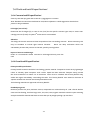
7.6.2 Gravel backfill specification:
Primary backfill specification:
Primary Backfill material should be free-flowing granular material. Compaction should be by lightweight
rollers or vibratory plate compactor until “traffic” depth has been achieved. Compact evenly, around
the turret extensions to reduce risk of distortion. Tanks must be installed with Primary Backfill only
within the region immediately surrounding the tanks. This Primary Backfill must extend a minimum of
250mm outward from the tank and directly beneath the tank.
The following materials are approved as Primary Backfill:
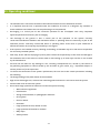
Rounded pea gravel:
Minimum particle size 3mm, maximum 18 mm, compacted to a relative density of >70%. Gravel shall be
clean and free flowing, free from large rocks, dirt, sand, roots, organic materials or debris. Upon screening
analysis the backfill material shall have no more than 5% by weight passing 2.36 mm Sieve
Or
12
Crushed or processed stone:
Minimum particle size 3 mm, maximum 12 mm, compacted to a relative density of
>40%
Dry Gravel density must be at least 1500 kg/m3. Material should be washed or screened to remove
fine particles. Upon screening analysis the backfill material shall have no more than 5% by weight
passing 2.36 mm Sieve
Use of other than specified backfill and bedding materials will void the tank
warranty.
Backfill material shall not be frozen or contain lumps of frozen material at any time during
placement.
Pea gravel
Crushed stone
7.6.3 Top soil:
Clean native top soil shall not contain rocks larger than 36mm on largest
dimension.
Note: The use of geo textile barrier fabrics surrounding the primary backfill material is considered
good installation practice. The fabric must be chosen to allow the flow of water in and out of the
excavation but to prevent the movement of fine soil particles into the primary backfill material.
7.6.4 Burial depth:
Generally, the max depth from finished to the inlet invert level of the main shell should be no more
than 725mm. This may vary dependent upon ground water conditions.
7.6.5 Loadings:
If the tank is installed in an area where traffic or other superimposed loadings can be applied, consult
a structural engineer for the design of a reinforced concrete slab to prevent the load being transmitted to
the tank (or its concrete surround). If this slab is constructed immediately above the tank, it
should be separated from the concrete surrounding the tank by a compressible material.
13
8. Plumbing the system:
Do not: Plumb storm-water (water) from roofs, drains, footpaths etc, into the Tricel septic tank. A competent
person in accordance with this manual should connect the plumbing from the dwelling to the septic tank. The
septic tank is plumbed for 110mm, uPVC pipe. The pipe should be vented by means of a vent pipe above the
eaves of the house. A short length of pipe with flexible joints should be used immediately before and after the
tank to allow for movement between the tank and the pipe work.
Note: water logged sites
The TricelSeptic tank is not suitable to be used in a water-logged site. Please contact the supplier of the system if
there are difficulties on site due to adverse water logging. Adequate drainage is important to improve wet sites,
or sites with a high water table level. It is critical that water is removed from the area
8.1 Treatment of effluent liquid:
The septic tank acts as a holding chamber and treatment of effluent is carried out in the percolation
area. Effluent may be disposed into any of any of the following means for treatment:
•
Drainage field (UK)
•
Drainage mound (UK)
•
Percolation area (Ire)
The best disposal method can depend on a variety of site factors including percolation results, soil type,
water table level and topography of the site. Please refer to the onsite engineer for further details.
8.2 Distribution box:
A distribution box and inspection chamber should be fitted between the tank and the percolation area. A
Distribution Box should be used to correctly construct the percolation trenches. The percolation trenches
are set out in a continuous loop from the Distribution box. An access chamber should be placed before and
after the septic tank for sampling and inspection purposes and also to assist in any blockages that may occur.
Distribution box. 450mm high x 300mm opening
Riser extension. 300mm opening x 270mm high
14
8.3 Sampling chamber:
A chamber must be fitted after every unit to allow easy access for sampling purposes. The inlet of
the chamber must be 150mm up from the base of the chamber to facilitate sampling cup.
9. Finishing the garden to ground level:
9. Finishing the garden to ground level:
The finished ground level should be to the level indicated on the system.
9.1 Ventilation:
Ventilation is crucial to the system. Prior to installing the system, great care must be given, on how to
provide adequate ventilation. As sites differ, advice is available from BS8301, BS6297, EPA wastewater
Treatment Manuals 1999, and the manufacturer. The Tricel Septic tank is supplied with 1No 110mm socket
next to the inlet pipe for venting.
15
10. Maintenance:
Precaution
Any maintenance carried out inside the tank represents a confined space. Therefore the maintenance person must be
suitably trained to work in confined spaces. Sewage and sewage effluent can carry micro-organisms and gases
harmful to human health. Any person carrying out maintenance on the system must be appropriately trained.
Suitable protective clothing; including gloves, goggles should be worn at all times. Always remove contaminated
clothing and protective equipment after completion of work. Wash hands and face prior to eating, drinking or
smoking.
A certain amount of system maintenance is required, on an ongoing basis to ensure that the system is
working correctly. This is the responsibility of the homeowner.
10.1 Quarterly Maintenance (3 months):
The outlet distribution box should be checked monthly to ensure that the, effluent is free flowing and clear.
The vent should be checked to make sure they are not blocked or covered with over grown grass.
10.2 Yearly maintenance:
De-sludging should be also carried out yearly to prevent solids rising to the height of the outlet pipe and
being carried along with the liquid into the percolation trenches. This blocks the percolation area and
can cause flooding. Depending on usage and house population, more frequent de-sludging may be
required. The de- sludging of the septic tank is the responsibility of the homeowner. De-sludging is done
with a vacuum tanker (we recommend the use of a licensed company).
10.2.1 De-sludging (emptying the solid waste from chamber 1 “primary chamber”)
•
Remove the access cover.
•
Empty the Tricel septic tank using a vacuum tanker. Care must be taken not to damage the tank with the
hose of the vacuum tanker.
•
Replace the de-sludging access cover securely.
Notes:
•
Do not let this equipment drive over the tank. Maintain a distance of at least 4 meters away
from the covers of the tank.
•
The access cover should never be left off while the unit is unattended.
•
De-sludging should never be carried out alone.
The property owner has a legal responsibility to ensure that the system does not cause pollution, a health hazard or
nuisance.
16
11. Operating conditions:
11. Operating conditions:
•
The manufacturer’s instructions outlined in the technical manuals must be followed at all times.
•
It is important that the unit is operated under the conditions for which it is designed. Any variation in
these conditions could lead to the unit not performing to its full potential.
•
De-sludging is a critical part of the successful operation of the Tricel Septic tank. Only competent
approved personnel should carry out de-sludging.
•
The discharge to the ground is also a critical part of the operation of the system. Correctly
constructed distribution chambers and distribution drains or polishing filters are necessary as part of the
treatment process. Incorrectly constructed drains or polishing filters could result in poor treatment of
effluent and we do not accept any responsibility in this regard.
•
If the system is not installed correctly, flooding, overloading, or floatation may occur. We are not responsible
for incorrectly installed systems.
•
Soak ways, drains and the emptying of primary tanks remain the responsibility of the client and damage to
the installation due to the influx of surface water or the backing up of soak ways or drains is not covered
by the manufacturer.
•
We shall not be liable for any damage or loss, including consequential loss, caused by the failure of
any plumbing equipment or failure caused by the inclusion of gross solids, (e.g. – disposable diapers or
sanitary towels etc) in the septic tank.
•
To ensure the continuance of the systems performance, the user has to take certain precautions including
the following:
•
The design loading of the plant should not be exceeded.
•
High volume discharges such, as those from swimming pools and Jacuzzi’s must never enter the system.
•
Surface water must not enter the system.
•
Do not allow large quantities of chemicals to enter the system including:
o
Water softener regenerate.
o
Disinfectants.
o
Strong acids and alkalis, or photographic chemicals.
o
Oil or grease.
o
Petrol or diesel.
o
Pesticides.
o
Large quantities of milk, alcohol or food.
o
Large quantities of bleaches or cleaners
o
Baby wipes
o
Sanitary towels
17
o
Kitchen paper
o
Nappies
•
Service personnel must be accommodated with clear access to the system.
•
If the system has been sized by others, we will supply a system to these specification and not its
own specifications. In this case, the responsibility lies with others, in relation to the maximum flow / litres
per day, the system capacity and retention times.
•
If we size the system, and a greater load is placed on the system by the addition of extra houses, bedrooms
in the houses, schools, crèche etc. or by any other means, we are not responsible for the system in
terms of overloading or the quality of the effluent as the retention times may be compromised.
•
The unit is not suitable for vehicular traffic. We also recommend fencing off the area to prevent livestock
herds from accessing the unit. Where possible, unnecessary human traffic around the tank should be avoided
Terms & conditions
Subject to our standard terms and conditions, which are available on request.
In accordance with our normal policy of product development, this specification is subject to change
without notice.
March 14
18
19