1
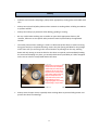
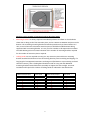
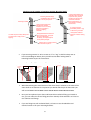
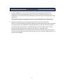
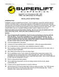
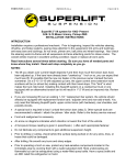
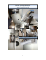
INSTALLATIONMANUAL
LaundryChuteSolutionsLtd
LaundryChuteInstallationInstructions
1
Index
PageNumber: 1 FrontCover
2 Index
3Introduction
4Safety
5
Tools&FixingsRequired
6
PlanningYourChute
7
Workingoutthenumberofmountingbracketsrequired
8
Workingoutthenumberoflockingbandsrequired
9
InstallingtheChute
10
2.1Installingamountingbracketstraightontoawall
11
2.2Installingamountingwhenitstandsoffthewall
12
3Assemblingthechuteintothebrackets
13
MountingaSurfaceMountedChuteDoor
14
MountingaFlushMountChuteDoor
15
InstallingaFireDamperCurtain
16
FinishingTouches
17
Operating&Maintenance
2
Introduction
•
Thankyouforconsideringordecidingtopurchaseoneofourlaundrychutes.LaundryChute
SolutionsLimited(LCS)manufactureallourowncomponentsfromhighgradematerialsin
theUK,specificallydesignedtobeinstalledintonewandoldbuildings;takingintoaccount
thetypesofconstruction,buildingmaterialsandlayoutsthatarecommonlyusedhere.
•
OurlaundrychuteisaoneͲoffpurchase.Thinkitthrough,planitwellandonceinstalled,it
willcostnothingtorun,isvirtuallymaintenancefreeandwillprovidealifetimeoftrouble
freeoperation.Getitright,becauseyouwilluseiteveryday.
•
Thismanualisinvaluableasanaidtohelpdesignachuteforyourneedsanddeterminethe
componentsrequired.Pleasereadtheentiremanualtohelpyoufullyappreciatewhatis
involvedandeasetheorderingandinstallationprocess.
•
OurchutesareeasytoinstallandeventhosewithabasicunderstandingofDIYcanachieve
aperfectendresult.Byensuringyouhaveagoodunderstandingoftheseinstructions,the
installationwillbeeasierandmistakeseliminated.
•
Allourchutecomponentsaremadefromthehighestgrade,30Ͳminutefireresistant
stainlesssteel(1.4301)available.Weareunawareofanyothercompanyusingsuchhigh
gradematerial.Don'tbefrightenedtoaskforthespecificationandproofoffireratingif
comparingourproduct.Weareunawareofanyimportedchutes(includingfromGermany)
thatcomplywithsuchhighstandards.
•
Thecomponentdrawingsaccompanyingthismanualrepresentourstockitems.Virtuallyany
configurationcanbedesignedusingthesecomponents;however,weareabletomake
specialcomponentsforbespokerequirements.
•
Thismanualprimarilydealswith300mmchuteinstallationsindomesticapplications,
however,theprincipalsarethesamefora400,500or600mmchutesuppliedbyusfor
commercialpurposes.
•
Ifyourequirehelporhaveaquestion,whatsoever,pleasecalloremailus:
01981540836Ͳ[email protected]
3
Safety
•
Stainlesssteelcontainssharpedges,alwayswearappropriate,sturdyglovesandhandlewith
care.
•
Alwayswearahardhat/safetyhelmetwhensomeoneisworkingabove.Afallingscrewdriver
orspannerwillkill.
•
Alwayswearsafetyeyeprotectionwhendrilling,grindingorcutting.
•
Beverycarefulwhenworkingoverorwithinanopenshaft.Appropriateharness,fall
restraint,fallarrestorsitespecificsafetymeasuresmustbepracticedbytheappointed
installer.
•
Thesafestpracticewhenworkinginashaftistobuildsturdyfalsefloorsateachlevelusing
hungjoistsandplyorchipboardflooring.Ensurethejoistspacingwillallowforthepassage
ofthechutesizeyouareusinginthecorrectlocation.Bystartingfromthetop,working
downandonlycuttinganaccurateholeforthechuteasrequired,andimmediatelyfeeding
thechuteandclampingitinplace,youvirtuallyeliminatethepossibilityofafallordropped
tools.Youcanalsouseastepladderwithinthechute.
300mmHolecutinthefalsefloor
andthenthechuteimmediately
insertedreadytobeliftedupand
clampedtotheTeepieceabove,
whichwillinturnconnecttothe
chutealreadypokingdownfrom
above.Ifacomponentisleft
opensimilartothispicture,then
placesomethingontopto
preventfallingtools.Thismethod
avoidsworkinginanopenshaft.
x
Alwayscovertheopenchute,especiallywhenworkingabovetopreventfallingmatterand
protectthechutefromdamage.
4
Tools&FixingsRequired
•
Hacksawordisccutter
•
Pencil
•
6ftspiritlevel
•
Shortlevelorscaffoldlevel
•
13mm&17mmSpannerorsocketratchet
•
4mmAllenKey
•
Pliers
•
SDSDrillwith10&12mmdrillbits
•
10mmWallplugs
•
8mmCoachscrews
•
10mmThreadedbar
•
Chemicalanchorkit
•
Stepladder
5
PlanningYourChute
•
AlaundrychuteinstallationisaoneͲoffpurchase.Onceinstalled,itcostsnothingtorun,is
virtuallymaintenancefreeandwilllastaslongasyourpropertyexists.Getitrightbecause
youwilluseitEVERYDAY.
•
Ifyouarebuildinganewpropertythenthechutecanbedesignedandeasilyincorporated
duringthebuild.
•
Attempttokeepthedropassimpleandverticalaspossible.Rememberthatanychuteis
betterthannone;iftheoverridingbuildingdesignorexistingstructureprecludethedoor(s)
orchuteterminationfrombeingintheperfectlocation,itisstilleasiertomakeashortwalk
onthesamefloortodepositorretrievelaundrythancarryingitdownstairs.
•
Ifyouhavethreeormorefloors,don'tignorethelevelswithoutbedrooms.Youstillneedto
washhandtowelsandteacloths;adiscreetchutedoornearthekitchen,whenthereisa
laundryorutilityroombelowwillproveinvaluable.
•
Determineyourchutelengthbymeasuringthetotaldroptoincludethefloordepths,top
doorheightandterminationpoint.Makingascaledrawing,andthenusethecomponent
technicaldrawingsonourwebsitetoachieveadesignanddeterminetherequired
components.Thesuggesteddesignsonaccompanyingsheetsmayalsoprovidehelp.
•
Alternatively,simplyemailusyourplandrawingstoincludesomeelevationmeasurements
andwewilldesignachuteforyouͲ[email protected]
•
Whenmeasuringyourdropandestablishingthecomponentsrequired,bearinmindthat
thereisa65mminsertontheflaredfemaleendofthechutecomponent.Therefore,when
youconnecttwocomponents,youwilllose65mminlength.Forinstance,thetotallengthof
2x1000mmextensionpiecesis2935mm.
•
Whendeterminingthechutelocation,takeintoaccountthesizeoftheencasementrequired
ifcreatingaboxingaroundthechute.Thesizesoftheboxingaredifferentforsurfaceand
flushmountdoors.Ifyouwantthesmallestpossiblechuteencasement,thenyouwillhave
touseasurfacemountdoor.Seethediagramonthefollowingpage.
6
Workingoutthenumberofmountingbrackets&lockingbands
•
Mountingbracketsarealwaysrequiredimmediatelybelowa90°elboworclosebehinda
chutedoororbungonthefirstextensionpiece,andona50mmor1000mmendpieceatthe
bottom.Theremainingmountingbracketsshouldbespacedevenlyasshownbelow.Asa
rule,nomorethantwoconsecutiveextensionpiecesshouldbeinstalledwithoutbeing
supportedwithamountingbracket.Itisveryrareforabrackettoberequiredonanelbow.
Thetablebelowgivesanaccurateindicationofthenumberofmountingbracketsrequired
forthenumberofextensionpiecesrequired.
•
Lockingbandsarenotrequiredateveryjoin.Anyextensionpiecewithoutamounting
bracketattachedshouldhaveatleastonelockingbandtopreventtwistingandslipping.Ifa
longlengthofunsupportedextensionsarebeingused(feddownorupanexistingenclosed
shaftforinstance),thenalockingbandshouldbeusedoneveryjoinandadditional
mountingbracketslocatedbelowthisassemblytosupporttheextraweight.Anormal
installationwillrequirethenumberoflockingbandsasindicatedinthetablebelow.
Totalnumberof500mmand
1000mmextension/endpieces
2
3
4
5
6
7
8
9
10+
Numberofmounting
bracketsrequired
Totalnumberof500mmand
1000mmextension/endpieces
Numberoflocking
bandsrequired
2
2
3
4
5
6
7
8
9
10+
1
1
2
2
3
3
4
4
5+
2
3
3
4
4
5
5
6+
7
Workingoutthenumberofmountingbrackets&lockingbands
Locking band between the
extension piece and elbow
to prevent heavy laundry
knocking the elbow down
and off the extension
piece. Alternatively, you
could install a mounting
bracket here.
Mounting bracket always
immediately below the lip
of the top component.
Mounting brackets
Locking band located here
because this 1000mm
extension has no mounting
bracket and is liable to
twisting or slipping
otherwise.
A mounting bracket
immediately below a "jog"
or elbow is a good idea.
Unsupported 1000mm
extension needs a locking
band.
Unsupported 500mm extension
has a locking band. The upper
band is not absolutely
necessary, but helps keep the
chute perfectly straight.
The final end piece nearly always has
band to help prevent
a locking
slipping.
Always have a mounting bracket
on the final end piece.
x
x
Ifyouareusingtwo45°or30°tocreatean“S”or“Jog”toshiftthedropoveras
intheseconddiagramabove,thenyouwillneedtoaddalockingbandor
mountingbracketaspertheinstructions.
Whenplanninga“jog”thefollowingmeasurementsmaybeuseful.
45 degree 700mm approx
elbow
500mm
extension
piece
30 degree
jog
45 degree
jog
x
370mm approx
140mm approx
Whendeterminingtheexactlocationofthechutedropinrelationtothesidesofthe
chuteshaftorencasementitisimportantyoudecidewhichstyleofchutedooryou
willuseandREADTHELAUNDRYCHUTEDOORINSTALLATIONINSTRUCTIONS.
x
Onceyouhaveplannedyourchuteandknowwhatmethodoffixingyouintendto
use,youcanorderthecorrectfixingpartsfromLaundryChuteSolutions.Itisbestto
usestainlesssteelfixings.
x
Ifyouarefixingintosoftinsulationblock,itisbettertousethreadedbarand
chemicalanchortofixyourmountingbrackets.
8
Installingthechute
1. Startby“peggingout”yourchuteandmarkingthetopandbottomlocationsofeach
componentonthewall.Remembertotakeintoaccountthe60/65mmoverlapofthe
components.Atthesametime,dropaplumblineormarkthecentrelineofthechuteusing
alonglevel.
Lookatthechutedoormountinginstructions–Thiswillhelpplanyourchutelocation.
2. Establishthelocationsofyourmountingbracketsandsecurethemtothewall.
Therearetwowaysoffixingthebracketsdependingonhowfarthechuteneedstostandoff
thesupportingwall.Ifthebracketsarebeingfixeddirectlytothewall,thentheyholdthe
chute50mmoff,andinstruction2.1belowshouldbeused.Ifthechuteneedstostand
furtherthan50mmawayfromthewall,theninstruction2.2shouldbeused.
Notallmountingbracketsneedtomountoffthesamewall.Sidewallscanalsobeused.If
youwanttomountthechutetighttothebackwall,thenthemountingbracketswillhaveto
mountonthesidewall.
9
2.1Installingamountingbracketstraightontoawall
Examplesofmountingbracketsattachedstraight
tothewall
Bracketscanbepackedoutoffthewallifrequired
2.1aOfferupthemountingbracketwiththecutout“V”in
themiddleofthebracketonyourmarkedcentreline.
Makesurethebracketislevel.
2.1bMarkthefourovalfixingholesonthebracketand
thendrill4x10mmholestothedepthof60mm.
2.1cUse10mmwallplugs,M8x60mmstainlesssteel
coachscrewsandM8stainlesssteelpennywasherstofix
thebrackettothewall.
2.1dTheholesinthemountingbracketareovalandthe
smaller8mmcoachscrewsallowyoutomanoeuvrethe
bracketandensureitsitscentralandlevel.
10
2.2Installingamountingbracketwhenitstandsoffthewall
Examplesofmountingbracketshungawayfrom
thewall
M10Threadedbar
M10Stainlessnut
M10Washers
TIP:Onceyouhaveestablishedyourbracket
locations–drill,cleanholes,chemicallyanchor
andinsertthreadedbarsveryquickly–itsets
veryfast.
M10Stainlessnut
Thedistancebetweenthewallandbracket
mustnotbemorethan300mmunlessan
opposingbracketcanbeinstalledimmediately
adjacent.Inthisinstance,abetteroption
wouldbetoinstallatimberjoisttomountthe
bracket.
2.2aPlacethewallbracketon
thewallwithyourcentrelinein
themiddleofthe“V”cutinthe
middleofthebracketmounting
plate.Levelthebracketand
markthefourfixingholes.
2.2bDrillthefourfixingholeswitha12mmbittothedepthof70mm.
2.2cYoushouldhavealreadyobtainedthecorrectchemicalanchor,
blowerorholecleaningbrushbeforecommencementoftheinstallation.
Cleanthedrilledholesusingtheblowerorcorrectsizebrush.
2.2dCut4correctsize10mmstainlesssteelthreadedbar.Rememberto
takeintoaccountthat70mmofthethreadwillinsertintothewallandthe
bracketholdsthechute50mmoffthefixingpoint.Therefore,ifyourchute
needstostand100mmoffthewall,yourthreadedbarwillneedtobe
140mmlongtocreatea20mmexposedthreadonwhichtoplaceawasher
andretainingnut.
2.2eFilltheholeswithchemicalanchor.
2.2fInsertthecorrectcutsizethreadedbarturninginaclockwise
directionasyouinsert.
2.2gUsesmallbitsofwoodornailsunderneathtoholdthethreadedbar
levelifrequired.Readtheinstructionsforsettingtimes.
2.2hPlaceanM10stainlessnutoneachthreadandthenanM10penny
washer.Offerupthebracketandsecurewithpennywasherandnut.Do
notfullytightenyet.
2.2iTheholesinthebracketareovalandlargerthan10mmtoallowa
degreeofmovement.Itisusuallybettertofullytightenthebracketsafter
theentirechutehasbeenassembled.Thiswillallow“finetuning”toget
theexactdoorandterminationheightsaswellasaperfectlystraightdrop.
11
3
Assemblingthechuteintothebrackets
3.1 Thedecisiontostartfromthetoporbottomisapersonaloneandoftendictatedbythe
siteconditions.
3.2 Thechutecanbeassembledintothemountingbracketsandclampedupusingthe
lockingbandspriortothefinaltighteningofthemountingbrackets.Thiswillallowfind
tuningofthechutelocationandstraightness.
3.2aWheninstallingalockingband,makesurethereis
equaldistancetopandbottombetweenthefemale
flaredendoftheextensionpieceandtheedgeofthe
lockingband.
Equal distance
Equal distance
3.2bAttachtheovercentrecatchestothehook
bracketsandclosethecatches.Tightentheallenkey
headedboltssothatthelockingbandpullsuptight.
Makesurethesidewiththecatches,sitsontopofthe
sidewiththehookbrackets.
Thereisnoparticularbestlocationforthelockingband
jointositonthechutecircumference.
3.2cOnceyouarehappywiththechutelocation,you
cancabletieorsqueezethecatchsidesusingpliersto
preventthecatchfromeverundoing.
3.3 Lockingbandsarenotrequiredoneverycomponent,andtheplanninginstructions
regardingtheiruseshouldberemembered.Ifnecessary,reͲreadtheseinstructions.
12
The Surface Mount Door has a
100mm male spigot on the back that inserts into the 90
degree elbow or TEE piece. We recommend a minimum
of 20mm insertion/overlap so the finished wall on which
the door mounts must not be built further forward than
230mm to its finished surface from the edge of the chute
drop, or 80mm from the finished edge of the opening.
Mounting
Instructions for
300mm Surface
Mount Door
Fireproof
plasterboard
Fixing screws are hidden
behind the door.
Max 80mm
For safety we
recommend
centre door be
at least
1000mm from
finish floor.
100mm
373mm
No more than an 80mm
gap here.
min 150mm & max 230mm
Requires plywood
behind and cut close
to the opening lip of
the 90 degree elbow/
T-piece to allow the
door to have a
secure fixing.
Wall bracket
1000mm min. off finished floor
50mm
Facing view of door
Fixing bolt
(Not visible with door
closed)
373mm
Doors are 373mm x
373mm
hhhhhh
1 hour fire rated
hhhhh
Child locks as
standard
hhhhh
Available in
powder coated
white or brush
stainless
steel
hhhhhh
Flush fitted
handles
Overhead view of chute boxing
The laundry
chute boxing
must be a
minimum of
420mm x
500mm.
Wall bracket
Min 420mm
50mm
Min 150mm & max 230mm
300mm
Laundry chute
door
Min 500mm
PLEASE NOTE: If you want the chute boxing to be as small as possible; the mounting bracket can
be hung from the side and Laundry Chute Solutions can supply a 90 degree or TEE piece with a
much shorter forward facing protrusion. A minimum 400mm front to back measurement is
achievable. The 420mm side to side measurements is always require to accommodate the door.
FLUSHMOUNT300MM1ͲHRFIRE
RATEDDOORINSTALLATION
INSTRUCTIONS
Plasterboard. If you want to ensure the fire rating integrity of the
door/chute encasing, then this needs to be fire board with 1hr
rating. E.g. 2 x 30 minute boards. There is only 30 minute rating
required by building control in most domestic UK applications,
but all our doors are minimum 1hr rated.
There is a 25mm overlap surround
on the front finished surface of the door.
Timber or metal batten all the way around the circumference of the hole in the
plasterboard for the chute door. The whole should be A MINIMUM 326mm square.
To make sure the door is completely rigid and very well fixed; the two upright studs
should be full length and be fixed top and bottom with the horizontal noggins attached to
these vertical studs. DO NOT MAKE THE OPENNING TOO TIGHT AS PACKERS CAN
ALWAYS BE USED TO ENSURE A TIGHT FIT. Do remember though, that there is only a
25mm flush-mount over lap on the door front to conceal the hole and prevent any making
good.
There are fixing holes through the box section
that slides into the prepared hole in the
plasterboard. When the door is in the correct
location, open the door while supporting it
(this is much easier with help) and use screws
through these holes to fix into the timber
batten.
60mm
27mm
290mm
Laundry Chute Solutions always recommend that
our chute doors are mounted a minimum of
1000mm to the centre, off the finished floor and
have a child-proof lock for added protection.
326mm
IMPORTANT: This dotted line represents the
internal spigot that bridges the chute door
and the stainless steel chute coupling
immediately behind. There is only a 27mm
protrusion for insertion into the stainless
coupling so the finished front surface of the
chute encasement must be NO MORE than
112mm and NO LESS than 95mm from the
finished open edge of the stainless steel
coupling (either 90 degree elbow or "Tee"
piece) that is left in situ during first fix. This
will allow a minimum of 10mm and maximum
of 27mm overlap into the stainless steel chute
component.
373mm
THIS BRIDGING SPIGOT IS AVAILABLE IN
A LONGER OPTION IF REQUIRED AND
THE MOUNTING SURFACE NEEDS TO
BE FURTHER FORWARD THAN THE
MEASUREMENTS BELOW.
70mm
455mm
95mm
50mm
This dimension may differ if the
mounting bracket has been held off
the wall on threaded bar.
Diagram showing recommended internal stud-work
for mounting of door.
min 326mm
min 326mm
min 1000mm to centre of door
Fire Damper Installation Instructions
10mm Stainless nuts and penny washers
1000mm or 500mm extension piece
10mm Stainless threaded bar
Wall mounting bracket mounted
just underneath the collar on the
extension piece.
10mm Threaded bar chemically
anchored. Minimum 70mm inserted
into wall.
Locking band located here
will enable the extension
piece to be offered up and
positioned correctly prior to
riveting the extension piece
to the top adaptor reducer.
The locking band is then
retained to ensure
absolutely no slipping of the
extension piece into the
adaptor.
3 x countersunk stainless steel 4mm
rivet inserted from inside the chute.
360mm
The bottom of the extension piece inserts
into the top adaptor but MUST NOT insert
as far as the damper. It MUST NOT
infringe the fire curtain and prevent the
damper from activating and closing the
chute off in the event of a fire.
This insertion is VERY IMPORTANT to
ensure the laundry by-passes the fusible
link that retains the fire curtain and breaks
at 72 degrees C. Without this insert,
laundry can get caught on this link.
Maximum 300mm, minimum 200mm
inserted into the adaptor reducer
Top fire damper reducer spigot
either 300mm to 600mm or 400mm
to 600mm. the adaptors are different
and specifically designed for top and
bottom. Make sure the correct one is
fitted. The top one has a male
600mm spigot and the bottom one
has a female 600mm collar.
This measurement will vary
depending on the position of
the adaptor. However, it will
be between 120mm & 230mm
The larger off-set of the adaptor reducer
MUST be located on the side of the
fusible link and fire curtain.
75mm
70mm
3 x countersunk stainless steel 4mm
rivet inserted from inside the adaptor
reducer.
360mm
The bottom adaptor reducer MUST
insert into the extension piece
below.
The 50mm surrounding lip on the top of the
fire damper should sit on top of the floor
with no gaps around it. This can be fixed
by drilling the lip approximately 20mm in
from the edge and a bead of fire-proof
mastic placed between the mating
surfaces. However, if the floor is yet to be
screeded, additional boarding laid tight to
the adaptor reducer or the entire assembly
is secure and solid after completing the
installation, then this is not necessary.
The lip nearest the wall can be cut if
required, but be careful not to damage the
damper/fire curtain enclosure and seal the
mating edge with fire-proof mastic or foam.
The fire damper needs to be
incorporated into the floor or sit on
top with the fire damper flange
supported on the floor. Once the
chute above is fixed, this will ensure
the damper does not move. No gaps
should be apparent and sealed with
fire retardant foam. Seal the damper
to the floor with fire-proof mastic.
If the damper is being mounted to
the underside of the floor, then the
flange will need to be supported
using uni-strut and threaded bar.
Fire curtain retained by
the the fusible link.
Ensure any cable
tie or any safety
device is removed
from this link
before closing off
the damper.
Wall bracket fixed off the wall using 10mm
stainless threaded bar chemically
anchored.
FinishingTouches
Ifyouareusingachutelidonthetop,thenusethe“U”profiletrimsuppliedwiththedoor
tocoverandprotectthesharpflarededge.
Firmlypushthetrimdownontheedgearoundthe
parameteruntilthetwoedgesmeet.
Cutthetrimwitha5mmto8mmoverlap.Firmlypush
thetwoedgestogethersotheymatecloselyandthen
finishpushingdowntheremainingtrim.
IfyouhaveanexposedunͲrollededgeonthebottomof
thechute,thenyoucanalsousethetrimtoprovidea
neatfinishandprotectthesharpedge.
Ifyouhaveachuteprotrudingthroughtheceilingandtheedgethatmateswiththe
plasterboardorcupboardroofneedstobetidied,thenuseaholehidertrimthatsimply
gluestotheceilingwithgripͲfillorsimilar.
Operating and Maintenance
Chute Doors – 60 minute minimum fire rating by Chiltern International Fire in accordance
with BS476: Part 22: 1987. Test Report: Chilt/IF03029.
Laundry chutes are dangerous to small children. The door heights should be
sufficient to eliminate the possibility of children entering the chute and the child locks
should always be used if small children are present.
All doors have key locks as standard. The doors are finished with RAL 9003 white powdercoating. The middle of the doors should always be a minimum of 1000mm off the finished
floor level, but Laundry Chute Solutions recommend 1200mm as a minimum.
Wipe clean with a damp cloth and polish the exposed surfaces with a non-abrasive furniture
polish.
Fire Damper - If a fire damper is fitted, then the fusible link should be checked annually for
any signs of corrosion or wear. If the fire damper has been fired, then contact Laundry Chute
Solutions to inspect and re-set as necessary.
Look up or down inside of the damper to inspect for any trapped items or damage on a
monthly basis.
Tested to British Standard 1366-2:1999 and international standard ISO 10294-1:1996 (E) by BRE
Garston in Watford. Test report no. 232943 and CC235890. The damper passes the required 240
minutes up to 1200 degree Celsius whilst maintaining constant pressure under positive pressure
of 300Pa.
The damper was also tested at the Warrington Fire Research Centre to BS476 Part 20 Criterion
7.1.1 for 6 full hours. The validation report number is WFRC151309.
Chute Components - The laundry chute is 1.5mm welded or folded modular system, DIN
1.4301 quality glass bead blasted, stainless steel. The components are interlocking with
tension bands to prevent, twisting and sliding. The system is airproof to prevent heat loss. It
has no sharp edges for laundry to get caught and generates no static charge.
The laundry chute requires no mechanical maintenance. Any visible soiling or dirt can be
removed with a cloth and antibacterial cleaner. Any visible stainless parts of the chute can
be polished and cleaned using a good quality stainless steel cleaner available from most
supermarkets. A cloth attached to a broom handle or suitable extension can be used to
clean beyond normal reach.
If inaccessible soiling or odour is present beyond the scope of ordinary cleaning then contact
Laundry Chute Solutions Ltd. There is a charge for this service.
Once a month it is important to look up the chute and visually inspect the internal condition
of the stainless steel and check there is no laundry caught or resting within the fire damper
enclosure.
Laundry Chute Solutions Ltd
Meadow Lodge
Wormelow
Herefordshire
HR2 8EG
01981 540 836
www.laundrychutesolutions.co.uk
[email protected]