1
WATER SUPPLY
AquaPod is capable of delivering over 50 litres per minute when connected to a suitable mains supply. The high quality
inlet control set with its 3 bar operating pressure has been designed to make the most of what is available however the
performance of any Unvented system is only as good as the water supply.
In unvented systems both hot and cold services are supplied simultaneously from the mains so the maximum possible
on-site water demand must be assessed and the water supply should be tested to ensure it can meet these requirements. If
necessary consult the local water supplier regarding the likely pressure and flow rate availability.
It is important that site pressure readings are taken under dynamic flow conditions, high pressures under zero flow conditions
are not necessarily indicative of satisfactory performance. A minimum of 1.5 bar at 20 l/m flow should be available. Where
mains inlet pressures are likely to exceed 16 bar then an additional upstream pressure reducing device should be fitted.
A minimum of 22mm supply pipe-work should ideally be provided and existing 1/2” (15mm) cold mains pipe-work may need
to be upgraded. Hard water treatment should be considered in areas where content it greater than 200ppm, if required adjust
cylinder temperature to below 60 degrees.
SITING THE UNIT
AquaPod can be positioned more or less anywhere in the dwelling but it should be remembered that for every 1 meter that an
outlet is above the AquaPod, the pressure will be reduced by 0.1 bar. If siting outside the heated envelope of the dwelling such
as in a garage or outbuilding then frost protection should be provided and exposed pipework should be insulated.
AquaPod must be supported on a flat base capable of supporting the weight of the cylinder when full. The minimum
recommended cupboard size is 650mm square.
GENERAL INSTALLATION
COLD MAINS PIPEWORK
Run the cold main through the building to the place where the AquaPod is to be installed. Take care not to run the cold
pipe near hot water or heating pipe work so that the heat pick up is minimized. Identify the cold water supply pipe and fit an
isolating valve (not supplied).
A 22mm BS1010 stopcock can typically be used but a 22mm quarter turn full bore valve would be better as it does not restrict
the flow as much. Do not use “screwdriver slot” or similar valves.
Make the connection to the cold feed of the cylinder and incorporate a drain valve. Position the inlet control just ABOVE the
Temperature & Pressure Relief Valve (TPRV) mounted on the side of the cylinder. This ensures that the cylinder does not
have to be drained down in order to service the inlet control set. Ensure that the arrow points in the direction of the water flow.
Select a suitable position for the expansion vessel. Mount it to the wall using the bracket provided. Use the hose to connect to
the inlet control group.
BALANCED COLD CONNECTION
If there are to be showers, bidets or monobloc taps in the installation then a balanced cold supply is necessary. There is a
22mm balanced connection on the inlet control set. An alternative method is to split the inlet control set on to two parts. Site
the pressure reducing valve immediately after the incomming cold mains stopcock (typically under the kitchen sink). All outlets
in the house will be at 3 bar and thus automatically balanced. The expansion relief valve section must still be mounted just
above the TPRV on the cylinder. A 3/4”F-22mm compression adaptor will be needed (not supplied).
It’s important that consideration is given to access for maintenance of the valves. The immersion heaters are 375 mm long and
access space should be provided for possible future replacement
HOT WATER PIPEWORK
Run the first part of the hot water distribution pipework in 22mm. This can be reduced to 15mm and 10mm as appropriate for
the type of tap etc. Your aim should be to reduce the volume of the hot draw off pipework to a practical minimum so that the
time taken for the hot water is as quick as possible.
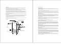
SCHEMATIC
Do not use monobloc mixer tap or showers if the balanced cold connection is not provided. The unit will back pressurise the
unit and result in discharge. Ensure that the top of the vessel is accessible for servicing.
* Do not fit shut off valve between Cylinder and Expansion Valve
Hot Outlet
PRIMARY COIL CONNECTIONS (Indirect Only)
Compression connections are provided for the primary circuit which must be positively pumped. Primary flow and return
connections are interchangeable to suit site conditions without affecting reheat times.
Expansion Vessel
With Wall Bracket
Temperature
& Pressure
Relief Valve
Non Return
Valve
Pump
Sealed or vented primary circuits can be used, to comply with normal installation practice the primary pressure should not
exceed 3 bar although the coil in Stelfow is suitable for up to 7 bar if required. The boiler may be Gas, Electric, Oil etc but
must be under effective thermostatic control. Uncontrolled heat sources such as some AGA’s, back boilers, solid fuel stoves,
etc may not be suitable please contact us for guidance. The two port zone valve should be installed into the primary flow
pipework leading to the coil flow inlet. The direction of flow arrow should be towards the primary flow connection. On twin coil
cylinders an extra thermostat boss is provided.
Expansion Relief
Valve
*
Tundish
Non Return
Valve
Isolating
Valve
Cold
Main
Secondary Return
Pressure
Reducing
Valve
2 Port
Valve
Boiler Flow
Dual
Stat
Drain Via
Cold Inlet
Balanced Cold Connection
Boiler Return
SECONDARY CIRCULATION
Where secondary circulation is required a circulator suitable for potable water should be used in conjunction with a non return
valve to prevent backflow. it may be necessary to incorporate an extra expansion vessel into the circuit to accommodate the
increased system water volume in larger secondary circulation systems. Where off peak electrical tariffs are being used then
secondary circulation should be avoided. A secondary return boss is fitted as standard on 210, 250 & 300L. On smaller sizes
tee into the cold feed pipe above the drain.
IMMERSION HEATERS
As a requirement of Building regulations the AquaPod immersion heaters are fitted with thermal cut-out in addition to the
normal control thermostat. To help ensure correct replacement the immersion heaters have a special 13/4“ thread. They are
of a low noise Incoloy construction and rated at 3 kW at 240 V. Replacement immersion heaters should be purchased via
ourselves otherwise your guarantee may be affected.
The ‘O’ring on the head of the immersion heater should be correctly positioned and lubricated before fitting . Screw in handtight until almost then gently tighten as the ‘O’ rings will seal easily. The electrical supply to each immersion heaters must be
fused at 13A via a double pole isolating switch to BS 3456. The cable must be 2.5mm2 heat resistant (85°C HOFR) sheathed
flex complying to BS 6141:1981 Table 8. Do not operate the immersion heater/s until the unit is full of water. If any sterilisation
liquid is in the cylinder do not operate the immersion heater/s as this will cause premature failure. Electric to be supplied by a
fused supply compliant with local regulations, and fitted by a qualified Part P Electrician.
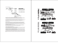
ENERGY CUT OUT AND CYLINDER THERMOSTAT (Indirect Only)
As a requirement of Building regulations the AquaPod units are fitted with a thermal cut-out in addition to the normal control
thermostat. This unit should be fitted to the dedicated boss on the cylinder and wired to the two port valve controlling the
primary flow.(see wiring diagram).