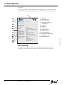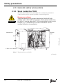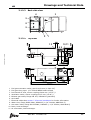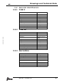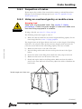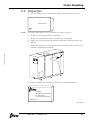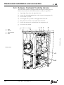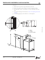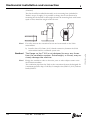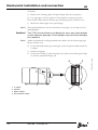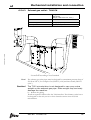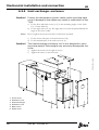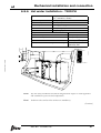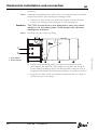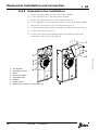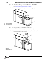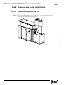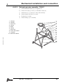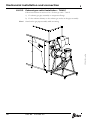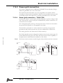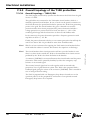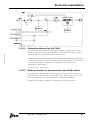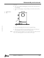
1
Installation Manual
Turbec T100
2.2T100s3_IMfro_rev02.fm
Series 3
Doc No. D12245-05
This document is valid for:
Series No/ Machine No
Sign.
Turbec T100
Copyright © 2006 Turbec Spa
2.2T100s3_IMfro_rev02.fm
All rights reserved. No parts of this document may be reproduced or
copied in any form or by any means without written permission from
Turbec Spa. The information in this document may be changed without
further notice. Reservations for misprints.
Version: 05
English
Issue 2006 03
Doc No. D12245-05
Turbec Spa
Via Statale 20/a
44040 Corporeno (FE)
Italy
1. Introduction
Equipment information . . . . . . . . . . . . . . . . 2
Purpose............................................................
Module description .............................................
Manufacturer...........................................
For maintenance ......................................
Identification ...........................................
CE marking .............................................
4
2
2
3
3
3
4
Document information . . . . . . . . . . . . . . . . . 5
IMserie3TOC.fm
Purpose of this Installation Manual .............
How to use this manual ............................
Design modifications ................................
Technical publications ...............................
Number of pages .....................................
Nomenclature and abbreviations ..........................
5
5
6
6
6
7
2. Safety precautions
2.1 Hazard information ..........................................
2.1.1 General ................................................
2.1.2 Sign for mandatory actions......................
2.1.3 Warning signs........................................
2.2 Personnel .......................................................
2.3 General safety precautions................................
2.3.1 Work inside the T100..............................
2.3.2 Generator .............................................
2.3.3 Remote control ......................................
2.4 Machine safety device ......................................
2.4.1 Emergency stop button ...........................
2.4.2 Extra emergency stop.............................
2.4.3 Doors and covers ...................................
2.5 Natural gas .....................................................
2.5.1 Classification .........................................
2.6 Equipment for lifting and moving loads ...............
10
10
10
10
11
12
12
14
14
15
15
15
16
18
18
19
3. Drawings and Technical Data
3.1 Installation drawings ........................................ 22
3.1.1 T100 P.................................................. 22
Doc No. D12245-05
i
3.2
3.3
3.4
3.5
3.6
3.7
24
27
28
29
29
29
29
30
30
31
32
33
33
Site preparation
4.1 Installation preparations ................................... 36
4.1.1 Installation preparations check list............ 37
4.1.2 Comments to the Installation preparations
check list .............................................. 39
5. Crate handling
5.1 Crate data.......................................................
5.1.1 Contents ...............................................
5.1.2 Weight and dimensions ...........................
5.2 Crate delivery..................................................
5.2.1 Indoor installation ..................................
5.2.2 Outdoor installation ................................
5.3 Lifting equipment .............................................
5.4 Unpacking area................................................
5.5 Unloading the crates.........................................
5.5.1 Inspection of crates ................................
5.5.2 Using an overhead gantry or mobile crane .
5.5.3 Using a fork lift ......................................
5.6 Moving and Storage .........................................
5.6.1 Moving..................................................
5.6.2 Storage.................................................
5.7 Opening the crates ...........................................
5.8 Unpacking the crates ........................................
ii
Doc No. D12245-05
44
44
45
45
45
46
46
47
48
49
49
51
52
52
53
54
55
IMserie3TOC.fm
4.
3.1.2 T100 PH................................................
3.1.3 Outdoor roof..........................................
3.1.4 Evacuation fan .......................................
General identification........................................
3.2.1 T100 P..................................................
3.2.2 T100 PH................................................
3.2.3 Gas turbine ...........................................
Noise..............................................................
Emissions .......................................................
Inlet/outlet connection data...............................
Electrical power specifications ............................
Auxiliary system ..............................................
3.7.1 Gas fuel booster.....................................
5.8.1 Unpacking crate A (Microturbine) .............
5.8.2 Unpacking crate B, C, E and F..................
5.8.3 Unpacking crate D (Heat exchanger).........
5.8.4 Unpacking crate G (Outdoor module) ........
5.9 Inspection ......................................................
5.10Disposal/return of packing ................................
55
57
58
60
61
62
6. Mechanical installation and connection
IMserie3TOC.fm
6.1
6.2
6.3
6.4
General requirements.......................................
Positioning ......................................................
Release transport locking device ........................
Installation instructions ....................................
6.4.1 Indoor installation ..................................
6.4.2 Outdoor installation ................................
6.5 Indoor installation............................................
6.5.1 Combustion and ventilation air induct
installation ............................................
6.5.2 Heat exchanger installation - T100 PH.......
6.5.3 Ventilation outlet installation....................
6.5.4 Exhaust gas outlet installation .................
6.5.5 Heat exchanger enclosure .......................
6.5.6 Hot water installation - T100 PH...............
6.5.7 Fuel gas installation................................
6.6 Outdoor installation..........................................
6.6.1 Outdoor air intake module.......................
6.6.2 Evacuation fan installation.......................
6.6.3 Heat exchanger installation - T100 PH.......
6.6.4 Ventilation outlet installation....................
6.6.5 Exhaust gas outlet installation .................
6.6.6 Heat exchanger enclosure .......................
6.6.7 Hot water installation - T100 PH...............
6.6.8 Chimney stabilizing ................................
Doc No. D12245-05
64
65
66
67
67
67
68
68
69
73
77
80
81
83
85
85
86
87
87
88
91
92
92
iii
7. Electrical installation
7.1 General requirements ....................................... 94
7.2 Overview ........................................................ 94
7.2.1 General information about cable
dimensioning ......................................... 94
7.2.2 Power grid connection ............................. 95
7.2.3 Overall topology of the T100 protection ..... 96
7.2.4 Selectivity ............................................. 98
7.2.5 Maximum voltage ................................... 98
7.3 Connecting to the electrical distribution grid ........ 99
7.3.1 Cable overview ...................................... 99
7.3.2 Cable entry ......................................... 102
7.3.3 Signal and cable details......................... 103
8.1 Unit configuration ..........................................
8.2 Parameter description.....................................
8.2.1 Document validity ................................
8.2.2 Pin code protection ...............................
8.2.3 Identity & fuel type - Site identity...........
8.2.4 Identity & fuel type - Fuel type...............
8.2.5 Heat production ...................................
8.2.6 Electricity production ............................
8.2.7 Custom BMS control .............................
8.2.8 Custom signal configuration ...................
8.2.9 Statistical data.....................................
8.2.10 Log data settings..................................
8.2.11 Alarm call service .................................
8.2.12 Software version ..................................
8.2.13 Test Mode ...........................................
iv
Doc No. D12245-05
110
110
110
110
111
111
112
115
118
120
121
122
123
124
124
IMserie3TOC.fm
8. Software configuration
9. Final installation checks
9.1
9.2
9.3
9.4
Installation and connection checks ....................
Lubrication and water level check......................
Safety checks.................................................
Start-up ........................................................
126
127
127
127
10.Preparation for commissioning
IMserie3TOC.fm
10.1Presence and correctness checks ......................
10.2Supply value checks ........................................
10.3Function checks ..............................................
10.3.1 Preparation ..........................................
10.4Health and safety checks .................................
10.5Documentation ...............................................
130
130
131
131
131
131
11.Disassembly and removal
11.1Draining - T100 PH .........................................
11.1.1 Draining procedure................................
11.2Moving the T100 microturbine ..........................
11.2.1 Short moves and short term storage........
11.2.2 Long moves and long term storage..........
11.3Return to the manufacturer ..............................
11.4Disposal ........................................................
134
134
136
136
137
137
138
12.Appendix:
Start-up machine quality report
12.1Transport damage report ....................................
12.2Installation and connection report ........................
12.3Lubrication and water level report ........................
12.4Safety report.....................................................
12.5Presence and correctness checks .........................
12.6Supply value report............................................
12.7Function report..................................................
12.8Health and safety checks ....................................
Doc No. D12245-05
b
c
c
d
d
d
e
e
v
IMserie3TOC.fm
This page is intentionally left blank
vi
Doc No. D12245-05
1. Introduction
2.2T100s3_IMint_rev02.fm
To ensure maximum safety, always read the 2. Safety precautions chapter before
doing any work on the equipment or making any adjustments.
Doc No. D12245-05
1
1. Introduction
Equipment information
Purpose
The Turbec T100 microturbine system is modular system designed to generate
power and heat. The T100 has several complementary modules to be used in a
large amount of applications.
Turbec will not accept any liability for damage to equipment or injury to
personnel caused by unauthorised or improper use of the Turbec T100
microturbine.
Module description
There are 4 different variants of the T100; 2 variants for indoor installation and
2 variants for outdoor installation.
T100 Power and Heat
The T100 Power and Heat unit (T100 PH) is the T100 P combined with an
exhaust heat exchanger, which allows the machine to produce combined heat
and power. The heat exchanger is delivered as a separate item, in addition to the
T100 P, and installed directly to the exhaust gas outlet side of the T100 P.
T100 Outdoor installation
In case of an outdoor installation, an outdoor roof is mounted on the T100.
The outdoor roof is delivered as a separate item. Besides the roof, a chimney
(for the exhaust gases) is included in the scope of supply. In the outdoor
installation, the coarse pre filter is included in the outdoor roof. The induced
draft fan is also mounted directly on the T100.
2
Doc No. D12245-05
2.2T100s3_IMint_rev02.fm
T100 Power
The basic module is the T100 Power (T100 P), which produces electrical power.
It is one complete module including the turbine, compressor, generator and
recuperator. An external coarse pre filter, and an induced fan are also required
for the installation.
1. Introduction
Manufacturer
This Turbec equipment has been manufactured by:
Turbec Spa
Via Statale, 20/a
44040 Corporeno (FE)
SE- 200 21 Malmö
Italy
www.turbec.com
For maintenance
Contact the nearest Turbec service station.
Identification
2.2T100s3_IMint_rev02.fm
All machines have an equipment sign for identification of the machine. The sign
is placed on the left side of the electrical cabinet.
Note!
The picture above with the machine sign position shows the Turbec T100 P.
(Continued)
Doc No. D12245-05
3
1. Introduction
(Continued)
The figure below shows an example of the equipment sign. The sign contains
data needed when contacting Turbec Spa concerning this specific equipment.
T100
SERIAL NUMBER:
YEAR/MONTH OF
MANUFACTURE:
VOLTAGE:
PHASES:
FREQUENCY:
RATED CURRENT:
POWER FACTOR:
NOMINAL SPEED:
AMBIENT TEMP:
RATED FUEL INPUT:
MANUFACTURER:
400 VAC
3 phases (T100 P/PH)
3 phases + neutral (T100 PS/PHS)
50 Hz
173A
0.8 leading to 0.8 lagging
70 000 rpm
-25 C to 40 C (indoor inst)
-10 C to 40 C (outdoor inst)
333 kJ/s
5
6
7
8
9
10
11
12
13
CE mark
Machine type
Serial number
Year and month of
manufacture
Voltage
Phases
Frequency
Rated current
Power factor
Nominal speed
Ambient temperature
Rated fuel input
Manufacturer
Turbec S.p.a.
Via Statale 20/A
440 40 Corporeno (FE)
Italy
www.turbec.com
CE marking
This equipment complies with the basic health, environment and safety
regulations of the European Community and European Economic Area.
4
Doc No. D12245-05
2.2T100s3_IMint_rev02.fm
MACHINE TYPE:
1
2
3
4
1. Introduction
Document information
Purpose of this Installation Manual
The purpose of this Installation manual is to provide technicians with
information on how to safely install this Turbec equipment:
It is important to:
• keep the manual for the life of the equipment
•
pass the manual on to any subsequent holder or user of the equipment
How to use this manual
This manual contains instructions for all different variants of the T100.
On the top of the pages a symbol is found to mark which variant/variants of
the machine the instructions are valid for. If there is no symbol on the top of
the page, the instructions apply to all variants.
2.2T100s3_IMint_rev02.fm
Note!
Some of the chapters have different sections for indoor and outdoor
installation. This is only indicated in the head-line of the specific chapter.
T100 Power generation
P
PH
P PH
Doc No. D12245-05
T100 Power and Heat
T100 Power generation
T100 Power and Heat
5
1. Introduction
Design modifications
The instructions in this document are in accordance with the design and
construction of the equipment at the time it was delivered from the Turbec
manufacturing plant.
Technical publications
The technical publications for this equipment are:
• Installation Manual
• Maintenance Manual
• Operator’s Manual
• Electrical Manual
• Spare Parts Catalogue
Updates and additional copies can be down-loaded at:
http//support.turbec.com.
Phone Helpdesk: +46 (0) 40 680 01 00
Fax:+46 (0) 40 680 00 01
Web site: www.turbec.com
When down-loading technical publications, always quote language and the
machine serial number and version or the document number that can be
found in the machine specification document.
Number of pages
This document contains a total of 154 pages.
6
Doc No. D12245-05
2.2T100s3_IMint_rev02.fm
To access the site, a log-in is needed. Contact Turbec Customer support for
more information at:
1. Introduction
Nomenclature and abbreviations
2.2T100s3_IMint_rev02.fm
The following nomenclature and abbreviations are used in the Installation
manual.
AC
Alternating Current
Auxiliary system
Lubrication, water cooling, air cooling, buffer air are all auxiliary systems
CE
Conformité Européene
Coarse filter
A coarse filter placed at outside air intake
Control panel
User interface for controlling the T100 microturbine
DC
Direct Current
Enclosure
The enclosure is where all systems, except the evacuation
fan, are installed in the T100 microturbine system
EMC
Electromagnetic compatibility
Evacuation fan
Ventilation fan which creates cooling and ventilation for the
T100 enclosure
Fine filter
Fine air filter for combustion air
Fuel gas system
Piping and valves connecting the gas grid to the T100
microturbine.
Heat exchanger
Exhaust gas heat exchanger for generation of heated water
Housing
Includes compressor, the turbine and the generator
MCB
Main Circuit Breaker
PLC
Programmable Logic Controller
PMC
Power Module Controller
T100 P
T100 Power Generation
T100 PH
T100 Power and Heat Generation
Standard International System (SIS) abbreviations are used for most
measurement
Doc No. D12245-05
7
1. Introduction
2.2T100s3_IMint_rev02.fm
This page is intentionally left blank
8
Doc No. D12245-05
2. Safety precautions
2.2T100s3_IMsp_rev02.fm
To ensure maximum safety, always read this section carefully before doing any
work on the equipment or making any adjustments.
Doc No. D12245-05
9
Safety precautions
2.1 Hazard information
2.1.1 General
Failure to observe information marked “DANGER!” puts your
life in danger.
DANGER!
Failure to observe information marked “WARNING!” can
result in personal injury and/or serious damage to, or
destruction of, equipment.
WARNING!
Caution!
Failure to observe information marked “Caution!” can result in
damage to equipment.
2.2T100s3_IMsp_rev02.fm
2.1.2 Sign for mandatory actions
Disconnect
voltage before any
work
2.1.3 Warning signs
10
Hot surface
Dangerous voltage
General danger
Hanging load
Risk of crushing
Powerful
magnetic field
Remote controlled
machine start
Inflammable
Doc No. D12245-05
Safety precautions
2.2 Personnel
Only skilled or instructed personnel are allowed to work on the equipment.
The manufacturer declines all responsibility for injury or damage if the
instructions in this manual are not followed.
Personnel are responsible for:
•
•
•
the equipment and the work area around the equipment
all personnel in the vicinity of the equipment
making sure that all safety devices are fully operational
Personnel must regard all electrical equipment as live. In general, switch off all
electrical connections to the T100 before carrying out maintenance or repair
work.
2.2.0.1
Electricians
Electricians should be certified according to local regulations and have
experience of similar types of installations, proven skills in reading and working
from drawings and cable lists, and knowledge of local safety regulations
regarding power and automation. Work with the electrical equipment must be
performed only by skilled or instructed technicians.
2.2T100s3_IMsp_rev02.fm
According to EN 60204-1, 3.28 an instructed person is:
– An individual adequately advised or supervised by a skilled person to enable that
individual to avoid hazards which electricity can create (e.g. operating and
maintenance staff).
According to EN 60204-1, 3.52 a skilled person is:
2.2.0.2
– An individual with technical knowledge or sufficient experience to enable that
individual to avoid hazards which electricity can create.
Gas fitters
Gas fitters should be certified according to local regulations and have
experience of similar types of installations, proven skills in reading and working
from drawings and knowledge of local safety regulations regarding gas and
automation. All work with the gas system should be conducted by locally
approved gas fitters.
Doc No. D12245-05
11
Safety precautions
2.3 General safety precautions
2.3.1 Work inside the T100
The T100 microturbine’s doors are locked with a standard key (Double bit
3 mm), and may only be opened by skilled or instructed persons.
DANGER!
Dangerous voltage
There are parts in the power electronics that hold high
voltage (up to 600 VAC see arrows) Some parts remain live
for up to 1 minute after the T100 microturbine’s main circuit
breaker (1) is switched off. In case of accident call for
medical attention immediately.
Cabinet side
Exhaust
side
2.2T100s3_IMsp_rev02.fm
1
1 Main circuit breaker
Note!
The picture shows a T100 P.
(Continued)
12
Doc No. D12245-05
Safety precautions
(Continued)
Work inside the T100 microturbine must be performed by skilled or instructed
persons only. Before any work is done inside the T100 microturbine, always
remember to:
a)
b)
c)
d)
Note!
Stop the T100, see Operator’s Manual, section: 3.2 Stopping the T100.
Wait 10 minutes to cool down the T100.
Switch off the T100’s main circuit breaker.
Switch off the external isolating switch for the grid network or remove
fuses.
The following instructions are just necessary for work inside the electrical
cabinet.
Switch off the 24 VDC including the battery backup to the PMC.
Wait a minimum of 1 minute to allow the capacitors to discharge.
Remove, if necessary, protections.
Verify absence of voltage with a voltmeter.
2.2T100s3_IMsp_rev02.fm
e)
f)
g)
h)
Doc No. D12245-05
13
Safety precautions
2.3.2 Generator
Dangerous voltage
During operation the voltage in the generator can be up to
600 VAC. The generator’s location is shown by the arrow. In
case of accident call for medical attention immediately.
Note!
The picture shows a T100 P.
2.3.3 Remote control
DANGER!
14
Remote controlled operation
The T100 microturbine can be remotely started, stopped and
accessed from a supervision unit, via a modem or computer
network or a Building Management System (BMS). To disable
remote start of the T100, disconnect the T100 according to
instructions (a)-(h) on page 13.
Doc No. D12245-05
2.2T100s3_IMsp_rev02.fm
DANGER!
Safety precautions
2.4 Machine safety device
2.4.1 Emergency stop button
Learn the position of the Emergency stop button in order to stop the
equipment in case of danger to people or damage to the equipment.
Pushing the Emergency stop button will reset the equipment and shut off the
fuel gas valves by a hard-wired loop thus stopping the engine. The electrical
power output will cease, as the main contactor between the power electronics
and the main circuit breaker will open.
The Emergency stop shall never be used for normal shutdown. Emergency
stopping may shorten the lifetime of the T100.
Note!
The picture shows a T100 P.
2.2T100s3_IMsp_rev02.fm
Note!
2.4.2 Extra emergency stop
The T100 is prepared for an extra wall mounted Emergency stop button. This
button is optional and should be located on a nearby wall. The function of the
extra Emergency stop button is the same as the Emergency stop button on
the T100.
Doc No. D12245-05
15
Safety precautions
2.4.3 Doors and covers
Do not remove doors and covers
Make sure that all doors and covers are in place and
functioning. Never remove covers while the equipment is in
operation.
WARNING!
Caution!
The T100 microturbine is protected by a pressure sensor to measure the
negative pressure in the enclosure. This sensor is part of the safety system and
must never be bridged, by-passed or otherwise made non-operational.
Never stop the equipment by opening a door or cover!
Some parts of the equipment protected by doors and covers
may be hot.
Do not walk on top cover
The top cover of the T100 microturbine is not designed to
carry the weight of a person.
In case of accident, call for medical attention.
The T100 microturbine’s doors are locked with a standard key (Double bit
3 mm), and may only be opened by skilled or instructed persons.
(Continued)
16
Doc No. D12245-05
2.2T100s3_IMsp_rev02.fm
WARNING!
Safety precautions
(Continued)
.
Service side view
1. Electrical cabinet door
2. Left front door
3. Right front door
4. Heat exchanger front cover
5. Heat exchanger right cover
6. Outdoor outlet front cover
7. Outdoor intake top cover
8. Outdoor intake front cover
9. Outdoor intake left cover
8
6
9
5
1
2.2T100s3_IMsp_rev02.fm
7
4
3
2
Back side view
10. Left back door
11. Right back door
12. Heat exchanger back cover
13. Outdoor outlet back cover
13
12
11
10
Note!
The pictures shows sides of a T100 PH, outdoor installation.
Doc No. D12245-05
17
Safety precautions
2.5 Natural gas
Risk of personal injury!
Natural gas is asphyxiating and inflammable. Carefully follow
the local instructions and gas regulations.
WARNING!
Follow the local regulations for handling of natural gas.
2.5.1 Classification
Gas group:
IIA
Temperature class:
T3
Zone 1:
ø3 m (ø9.8 ft)
Zone 2:
ø6 m (ø19.6 ft)
Note!
The picture shows a typical indoor installation. The classified zones are also
equivalent to outdoor installations.
Note!
The air inlet must be installed in a non hazardous area.
2
1
4
5
6
7
3
1 Zone 1, ø3 m
2 Zone 2, ø6 m
3 Fuel gas
evacuation
8
4 Exhaust outlet
5 Air ventilation outlet
6 Pre-filter
7 Air inlet
8 Fuel gas inlet
(Continued)
18
Doc No. D12245-05
2.2T100s3_IMsp_rev02.fm
The T100 has been evaluated according to the ATEX directive. Due to the
excessive ventilation, the calculations showed negligible size of zone 2 volumes
in case of any leakage inside the T100. No means of ignition are close to the
very small zones that can arise. The remaining installation is classified according
to IEC/EN 60079-10 and has classified zones. The perimeter must be
respected between the fuel gas evacuation and hazardous equipment.:
Safety precautions
(Continued)
2.5.1.1
Definitions (according to IEC/EN 6079-10):
Hazardous area:
An area in which an explosive gas atmosphere is present, or may be expected to
be present, in quantities such as to require special precautions for the
construction, installation and use of apparatus.
Zones:
Hazardous areas are classified into zones based upon the frequency of the
occurrence and duration of an explosive gas atmosphere, as follows:
Zone 0:
An area in which an explosive gas atmosphere is present continuously or for
long periods.
Zone 1:
An area in which an explosive gas atmosphere is likely to occur in normal
operation.
2.2T100s3_IMsp_rev02.fm
Zone 2:
An area in which an explosive gas is not likely to occur in normal operation and,
if it does occur, is likely to do so only infrequently and will exist for a short
period only.
2.6 Equipment for lifting and moving loads
WARNING!
Heavy load!
Make sure that the capacity of the lifting equipment is
adequate and that the equipment itself is in good working
order.
If lifting tackle has to be joined to make up the necessary lengths, make sure
that the joints are secure and have the same lifting capacity as the rest of the
tackle.
Always engage the safety clip on lifting hooks to prevent the tackle from
slipping off.
Use ropes or poles to steady and manoeuvre loads. Do not use hands or feet.
Make sure that the route and the destination are free from obstacles before
moving a suspended load. It must be possible to lower the load to the floor
quickly and safely in an emergency.
When depositing loads, keep the lifting equipment in place until the stability of
the load has been checked
Doc No. D12245-05
19
Safety precautions
2.2T100s3_IMsp_rev02.fm
This page is intentionally left blank
20
Doc No. D12245-05
2.2T100s3_IM3_rev02.fm
3. Drawings and
Technical Data
Doc No. D12245-05
21
Drawings and Technical Data
P
3.1 Installation drawings
3.1.1 T100 P
The following drawings show machine dimensions, connection positions and
dimensions, and access dimensions. All dimensions must be respected. All
dimensions are in millimetres, and with inches in bracket, unless otherwise
stated. Dimensions marked with * indicate inside width.
The following drawings are provided:
•
•
•
•
•
•
3.1.1.1
Top view with marked service area
Service side view
Rear side view
Top view
Cabinet side view
Outlet side view
Top view with marked service area
(4770)
1300
(3200)
900
2.2T100s3_IM3_rev02.fm
700
6,7
1400
6 x 700kg
SERVICE AREA
3.1.1.2
Service side view
Back side view
3
3
4
4
5
5
1
2
22
Doc No. D12245-05
Drawings and Technical Data
P
3.1.1.3
Top view
195
90
4
275
450
685
5
67
73
900
755
12
120
1620
3
1050
217
1050
2770
3.1.1.4
Cabinet side
Outlet side
CEILING
4
1810
5
1
2
1
2
3
4
5
6
7
278 300
1060
1
2
110
+25
-10
1910
2.2T100s3_IM3_rev02.fm
ARRESTO I EMERGENZA
EMERGENCY STOP
1542
TBD (2500)
6 73
Fuel gas evacuation outlet, pipe Ø 10/8 mm (0.39/0.32”)
Fuel gas inlet, pipe 1 1/2” internal BSPP female thread
Pre-filtered air inlet, sleeve coupling male Ø 400 mm (15.75”) *
Ventilation outlet, sleeve coupling male Ø 315 mm (12.40”) *
Exhaust gas outlet, flange Ø 319 mm (12.55”) *
Grid cable
Electrical cables See section 7. Electrical installation for further information
Doc No. D12245-05
23
Drawings and Technical Data
PH
3.1.2 T100 PH
The following drawings show machine dimensions, connection positions and
dimensions, and access dimensions. All dimensions must be respected. All
dimensions are in millimetres, and with inches in bracket, unless otherwise
stated. Dimensions marked with * indicate inside width.
The following drawings are provided:
•
•
•
•
•
•
Top view with marked service area
Service side view
Rear side view
Top view
Cabinet side view
Outlet side view
Top view with marked service area
3.1.2.2
Service side view
2.2T100s3_IM3_rev02.fm
3.1.2.1
3
24
Doc No. D12245-05
4
5
Drawings and Technical Data
PH
3.1.2.3
Back side view
4
3
5
8
9
3.1.2.4
Top view
2 1
10 11
12
89
4
5
2.2T100s3_IM3_rev02.fm
67
3
1
2
3
4
5
6
7
8
9
10
11
Fuel gas evacuation outlet, pipe Ø 10/8 mm (0.39/0.32”)
Fuel gas inlet, pipe 1 1/2” internal BSPP female thread
Pre-filtered air inlet, sleeve coupling Ø 400 mm (15.75”) *
Ventilation outlet, sleeve coupling Ø 315 mm (12.40”) *
Exhaust gas outlet, flange DN 315; DIN24154 (part 2&5)
Grid cable
Electrical cables See section 7. Electrical installation for further information
Water inlet, flange DN32 PN40; DIN2635 (1 1/4” 300Lbs; ANSI B16.5)
Hot water outlet, flange DN 32 PN40; DIN2635 (1 1/4” 300Lbs; ANSI B16.5)
Drain, heat exchanger
Air evacuation, heat exchanger
Doc No. D12245-05
25
Drawings and Technical Data
3.1.2.5
PH
Cabinet side
4
Outlet side
3
3
4
5
11
8
1
2
3
4
5
6
7
8
9
10
11
26
9
10
2
1
Fuel gas evacuation outlet, pipe Ø 10/8 mm (0.39/0.32”)
Fuel gas inlet, pipe 1 1/2” internal BSPP female thread
Pre-filtered air inlet, sleeve coupling male Ø 400 mm (15.75”) *
Ventilation outlet, sleeve coupling male Ø 315 mm (12.40”) *
Exhaust gas outlet, flange DN 315; DIN24154 (part 2&5)
Grid cable
Electrical cables See section 3. Drawings and Technical Data for further information
Water inlet, flange DN32 PN40; DIN2635 (1 1/4” 300Lbs; ANSI B16.5)
Hot water outlet, flange DN 32 PN40; DIN2635 (1 1/4” 300Lbs; ANSI B16.5)
Drain, heat exchanger
Air evacuation, heat exchanger
Doc No. D12245-05
2.2T100s3_IM3_rev02.fm
1
2
Drawings and Technical Data
PH
3.1.3 Outdoor roof
The following drawings show the outdoor roof dimensions, connection
position and dimensions for the outdoor roof.
For information about other dimensions of the T100, see section 3.1.1 T100 P or
section 3.1.2 T100 PH.
The following drawings are provided:
3.1.3.1
• Back side view
• Top view
• Cabinet side view
Back side view
2
1
2.2T100s3_IM3_rev02.fm
3
8
9
3.1.3.2
7
6
Top view
67
1
2
3
4
5
6
7
8
9
1 89
2
Ventilation outlet
Exhaust gas outlet
Air inlet
Grid cable
Electrical cables See section 7. Electrical installation for further information
Fuel gas inlet, pipe 1 ½’’ internal BSPP female thread
Fuel gas evacuation outlet, pipe Ø 10/8 mm (0.39/0.32”)
Water inlet (T100 PH), flange DN32 PN40; DIN2635 (1 1/4” 300Lbs; ANSI B16.5)
Hot water outlet (T100 PH), flange DN32 PN40; DIN2635 (1 1/4” 300Lbs; ANSI B16.5)
Doc No. D12245-05
27
Drawings and Technical Data
3.1.3.3
PH
Cabinet side
1
2
3
1 Ventilation outlet
2 Exhaust gas outlet
3 Air inlet
225 [8.86'']
172 [6.77'']
28
Mounting base
30 [1.18'']
13.5 [0.53'']
230 [9.06'']
ø12 [0.47''] (6x)
200 [7.87'']
160
[6.30'']
160
[6.30'']
38 [1.50'']
573 [22.56'']
Doc No. D12245-05
230 [9.06'']
400 [15.75'']
229 [9.02'']
298 [11.73'']
ø315 [12.40'']
outside
235 [9.25'']
ø314 [12.36'']
outside
40 [1.57'']
256 [10.08'']
398 [15.67'']
2.2T100s3_IM3_rev02.fm
3.1.4 Evacuation fan
Drawings and Technical Data
PH
3.2 General identification
3.2.1 T100 P
Characteristics
metric
Model
T100 P
Type
Microturbine
Application
Power generation
Usage
Indoors or outdoors
Weight, indoor installation
2250 kg
Weight, outdoor installation
2750 kg
Site flooring
Hard floor
Fuel
Natural gas
Surrounding air temperature
-10°C to 40°C
Max. surrounding air humidity
100%
2.2T100s3_IM3_rev02.fm
3.2.2 T100 PH
Characteristics
metric
Model
T100 PH
Type
Microturbine
Application
Combined Heat and
Power
Usage
Indoors or outdoors
Weight, indoor installation
2770 kg
Weight, outdoor installation
3100 kg
Site flooring
Hard floor
Fuel
Natural gas
Surrounding air temperature
-10°C to 40°C
Max. surrounding air humidity
100% non-condensing
3.2.3 Gas turbine
Characteristics
metric
Compressor type
Centrifugal
Turbine type
Radial
Type of combustion chamber
Lean pre-mix
Number of combustion chambers
1
Pressure in combustion chambers
4.5 bar (a)
Turbine inlet temperature
950°C
Number of shafts
1
Nominal speed
70 000 rpm
Doc No. D12245-05
29
Drawings and Technical Data
PH
3.3 Noise
The table below shows the maximum noise level measurement for the T100
microturbine under the following conditions:
•
•
•
Measurements on eight positions in accordance with ISO standard 3746
Machine fitted with standard feet placed on a concrete floor
Nominal operation, 100%, 70 000 rpm, 100 kW
These values are valid for indoor installation as well as for outdoor installation.
Characteristic
Symbol
Value
Rounded
notes
Emission sound
pressure level
LP
70 dBA
0.5 dB
1 m (3.3 ft) from T100
microturbine
Note!
30
Characteristics
100% load
Notes
NOx
< 15 ppm/v = 32 mg/MJ fuel
*
CO
< 15 ppm/v = 18 mg/MJ fuel
*
UHC
< 10 ppm/v
*
* Volumetric exhaust gas emissions at 15% O2 and 15°C air inlet.
Doc No. D12245-05
2.2T100s3_IM3_rev02.fm
3.4 Emissions
Drawings and Technical Data
PH
3.5 Inlet/outlet connection data
3.5.0.1
Characteristics
Metric
US measurements
Notes
Fuel gas pressure
0.02-1 bar (g)
0.3-14.5 psi (g)
Microturbine inlet
Fuel gas temperature
0°C to 60°C
32°F to 140°F
Microturbine inlet
1 154-1 476 Btu/
scf
Wobbe index
43-55
Max air mass flow at 15°C
(59°F)
1.69 kg/s
(=1.38 m3/s)
3.73lb/s
(=48.7 ft3/s)
Air inlet temperature
indoor installation
-25°C to 40°C
-13°F to 104°F
Air inlet temperature
outdoor installation
-10°C to 40°C
14°F to 104°F
Max air inlet humidity
100%
Max air particle size
1 mm
MJ/mn3
Non-condensing
Additional connection data for the Heat exchanger
Characteristics
Metric
US measurements
Notes
Water quality
2.2T100s3_IM3_rev02.fm
pH
6.5 - 8.0
Max water pressure
24 bar (g)
348 psi (g)
Max water volume flow
4 l/s
1.06 gal/s
Min water volume flow
1.5 l/s
0.40 gal/s
Min water inlet
temperature
50°C
122°F
Max water outlet
temperature
150°C
302°F
Total water volume of the
Heat exchanger
18.6 l
4.91 gal
Doc No. D12245-05
31
Drawings and Technical Data
3.6 Electrical power specifications
Characteristics
50Hz
Start-up voltage
400 VAC, 50 Hz
Nominal voltage output
400/230 VAC,
3 phase
Frequency output
50 Hz
Rated current
173 A
Max allowed mains
frequency variations
± 5%
Max allowed mains
voltage variations
± 10%
Adjustable power factor
0.80 leading to 0.80 lagging
5%
3%
Output circuit
3 phase + safety ground
Protection circuit
Short circuit protection
Thermal over current protection
Neutral is not needed
May be limited by max apparent power
2.2T100s3_IM3_rev02.fm
Harmonic current
according to IEEE 519:
Max total distortion
Max single distortion
Notes
32
Doc No. D12245-05
Drawings and Technical Data
3.7 Auxiliary system
Cooling water specifications
Characteristics
Value
Notes
Water circuit volume
10 l (2.6 gal)
50% water / 50% glycol
Water quality
See Maintenance manual
Glycol
Texaco Havoline XLC +B
ASTM D3306, D4656,
D4985
Consumption
0.5 litres/6 000 h
(0.13 gal/6 000 h)
Add glycol 50%, see
Maintenance manual
Lubrication oil specifications
Characteristics
Value
Notes
Oil circuit
Max oil flow
Approx. 3.5 l/min
(approx. 0.92 gal/min)
Type
MIL-L-23699
Consumption
3 litres/6 000 h
(0.80 gal/6 000 h)
See Operator’s manual
2.2T100s3_IM3_rev02.fm
3.7.1 Gas fuel booster
Lubrication oil specifications
Characteristics
Value
Notes
Oil circuit
Max oil flow
Approx. 5 l/min
(approx. 1.32 l/min)
Type
PAH compressor oil
See Operator’s manual
Characteristics
Value
Notes
Pressure min/max
0.02/1.0 bar (g)
(0.3/14.5 psig)
With fuel booster
Temperature min/max
0°C/60°C
(32°F/140°F)
Gas requirements
Doc No. D12245-05
33
Drawings and Technical Data
2.2T100s3_IM3_rev02.fm
This page is intentionally left blank
34
Doc No. D12245-05
2.2T100s3_IM4_rev02.fm
4. Site preparation
Doc No. D12245-05
35
Site preparation
4.1 Installation preparations
Please ensure that the dimensions of the installation site and the positions of
the connections comply with the values shown in the drawings, see section
3. Drawings and Technical Data and the section 3.1 Installation drawings.
Note!
Check that the required service area as shown in the drawings, complies with
the installation site. Check that the installation site is accessible for spare parts
delivery.
Check that the specifications for T100 microturbine’s connections comply with
the Turbec Spa requirements. In case of doubt, please consult local technical
personnel.
To find diagrams with correction of performance for T100 microturbine, see
Turbec Document D-12339 Technical Description, chapter 1.2.3. Correction of performance.
Note!
Check that the local legislation permits this type of microturbine installation,
and in particular the fuel gas system and electrical grid connection. In case of
doubt, please consult local authorities or local authorized technical personnel.
Please check the local legislation demands on personnel evacuation for the site.
•
•
•
•
Fuel gas
Electricity
Ventilation
Hot water
before the main installation of the T100 microturbine is performed, see section
6. Mechanical installation and connection for more details.
If any specifications do not comply, please contact Turbec Spa for guidance and
customizing.
36
Doc No. D12245-05
2.2T100s3_IM4_rev02.fm
It is possible to prepare parts of the installation of:
Site preparation
4.1.1 Installation preparations check list
Comments to the installation preparation check list are found in section
4.1.2 Comments to the Installation preparations check list.
System
Checks
Placement
Site access checked for the
microturbine dimensions
Remarks
Most narrow area to pass through
with the T100
(L x W x H)
Available service area
(L x W x H)
Available lifting device on site
Fuel system
x
x
m
x
x
m
Type:
Length of air supply ducts
m
Length of ventilation pipes
m
Length of exhaust gas pipes
m
Fuel quality analysed or approved
from supplier
Make a note of:
Lower Heating Value
Quality fluctuations
Fuel supply piping ready to turbine hall
Capacity and pressure levels are
sufficient
2.2T100s3_IM4_rev02.fm
Date/sign
MJ/Nm3
bar (g)
Fuel supply connection size and
type complies with counter flange
described in section 6. Mechanical installation and connection
Electrical system
Connection points ready
Grid connection permit
Local requirements fulfilled
Equipment ordered
Cable route arranged all the way
to the machinery
Cable area sufficient
Cable length
Air supply
mm
m
Filter installed
(indoor installation)
Air supply connection size and
type complies with counter flange
described in section
6. Mechanical installation and
connection
(Continued)
Doc No. D12245-05
37
Site preparation
(Continued)
System
Checks
Ventilation
Ventilation in the room (indoor
installation) approved by local regulations
Remarks
Date/sign
Ventilation connection size and
type complies with counter flange
described in section
6. Mechanical installation and
connection
Exhaust gases
Stacks installed
Stacks ready to be connected to
the microturbine
Exhaust connection size and type
complies with counter flange
described in section
6. Mechanical installation and
connection
Connection flange ready to be
connected to microturbine inlet
flange
Connection flange ready to be
connected to microturbine outlet
flange
Water connection size and type
complies with counter flange
described in section
6. Mechanical installation and
connection
Turbine room
Specify type of floor
Specify roughness of floor
Acoustic level approved by local
authorities (if required)
Remote control system
38
Access to a telephone line or
access to a GSM subscription in
case a GSM modem (option) is to
be used.
Doc No. D12245-05
2.2T100s3_IM4_rev02.fm
Hot water
(T100 PH)
Site preparation
4.1.2 Comments to the Installation preparations
check list
4.1.2.1
Placement of the T100
Turbec recommends to:
•
•
•
•
2.2T100s3_IM4_rev02.fm
•
mark with paint the limits of the indoor service area on the floor.
fence in outdoor installations to avoid damage and unauthorized operation.
avoid placement in areas that tend to be flooded or be covered in deep
snow.
if winds over 35 m/s [78 m.p.h.] can be expected, place the T100 indoors or
fasten the machine to the ground.
bolt or with other means fasten the machine to the ground in earthquake
zones. Please consult local authorities or local authorized technical
personnel to assess earthquake risk requirements.
Make sure it is possible to access the installation site for the T100. The T100 is
very compact and will pass through normal door openings, but due to the
length it might be difficult to pass corners in buildings, or when a door is placed
on one side of a corridor.
Note the most narrow area to pass through with the T100 in the check list on
the previous page.
All requirements for the service area must be met. Dimensions required
for this purpose are found in chapter 3 Drawings and Technical data.
Note the actual service area reserved for the T100 equipment in the check list
on the previous page.
Make sure there is access to lifting device meeting the requirements stated in
chapter 5 Crate handling.
Note the type of lifting device available for the installation in the check list on
the previous page.
Consider the length of air supply ducts, ventilation pipes and exhaust gas pipes
when placing the T100. The ducts must have sufficient dimensions since the
pressure drop will have an impact on the performance level of the T100.
(Continued)
Doc No. D12245-05
39
Site preparation
(Continued)
4.1.2.2
Fuel system
The fuel demand corresponds to a supply of heat of at least 333 kW based on
the Lower Heating Value (LHV), with a pressure in the range of 0.02 bar (g) to
1.0 bar (g).
Note the LHV for the fuel, and the pressure level in the check list on the
previous page. Also note if there is any fuel quality fluctuations.
Example:
For fuel gas with LHV =39 MJ/mn3, the volume flow required for continuous
production of 100 kW is 31 mn3/h and maximum 40 mn3/h under acceleration.
For a natural gas installation, the Wobbe index shall be in the range
43-55MJ/m3.
Note!
Make calculations on maximum pressure drop on site gas pipe installation, to
avoid under-sized gas delivery.
Note!
Other fuels than standardized natural gas has to be analysed and approved by
Turbec before installation.
4.1.2.3
Electrical installation
Make sure there are sufficient capacity for the connection points, and that the
grid connection is dimensioned to handle the power output from the T100.
Furthermore, make sure all local requirements are fulfilled, even the ones that
are site specific.
External cables, disconnecting switches and fuses must be ordered before
installation. See section 7. Electrical installation for further information about the
cables, switches and fuses. Note that long cables will add installation cost (but
with negligible transmission losses).
40
Doc No. D12245-05
2.2T100s3_IM4_rev02.fm
If the gas grid delivers high pressure gas; 6.0 - 8.0 bar (g), the fuel booster can
be removed from the T100. If the gas pressure is higher than 8.0 bar (g) a
reducing valve must be installed.
Site preparation
4.1.2.4
Note!
Air supply
Indoor installation:
The inlet air must be taken from a non-hazardous area (EN 60079-10). For
definition of hazardous area, see section 2.5.1.1 Definitions (according to IEC/EN
6079-10):.
The coarse pre-filter is an option for an indoor installation. Since air ducts,
between the T100 and the coarse pre-filter, are not included in the Turbec
scope of supply, they must be ordered.
Turbec recommends to mount the coarse pre-filter on an outside wall,
preferable on a wall facing north (better performance due to low temperatures).
The coarse pre-filter must be mounted so that rain or snow can not enter the
system.
All air ducts must be suspended properly in order to not add any extra forces
and weight to the connection flanges.
Outdoor installation:
For an outdoor installation, the pre-filter is integrated in the outdoor roof
module.
2.2T100s3_IM4_rev02.fm
4.1.2.5
Ventilation
Indoor installation:
Since air ducts between the T100 and the evacuation fan are not included in the
scope of supply, they must be ordered. Turbec recommends to insulate the
leaving air duct.
The evacuation fan is designed for outdoor use. Turbec recommends to mount
the fan as close as possible to the ventilation outlet.
All air ducts must be suspended properly in order not to add any extra forces
and weight to the connection flanges.
Outdoor installation:
For an outdoor installation, the evacuating fan is mounted directly to the
ventilation outlet on the T100.
Doc No. D12245-05
41
Site preparation
4.1.2.6
Exhaust gases
Indoor installation:
The length of the exhaust pipe is important since the thermal expansion
requires an expansion bellow if there are no possibilities to route the exhaust
gases directly out through the wall. If the exhaust pipe before the wall is longer
than 2-3 meters, an expansion bellow has to be ordered. An extra pressure drop
of 2 KPa means 5% less power output.
All air ducts must be suspended properly in order not to add any extra forces to
the connection flanges.
Turbec recommends to insulate the exhaust pipe.
Note!
The following instruction is only valid for indoor installations that intend to
fulfil the standard, Stationary Engine Generator Assemblies UL 2200:
Exhaust piping and chimneys shall be designed, constructed, and installed in
accordance with the Standard for the Installation and Use of Stationary
Combustion Engines and Gas Turbines, NFPA 37.
Outdoor installation:
4.1.2.7
Hot water (T100 PH)
If other heat sources are connected to the same heating system, it is beneficial
with a close distance due to pressure drop, thermal losses in the distribution
system and installation costs.
4.1.2.8
Turbine room
The floor shall preferable have a smooth, but hard, surface. It is recommended
to use a oil resistant layer of epoxy, or equal, as the floor might be exposed to
smaller amounts of oil spillage.
Some mobile lifting devices need a minimum clearance of 100 mm between the
floor and the machine. If the floor is not completely levelled, or rough in its
structure, a higher clearance is necessary. The clearance must be in the range of
100 to 135 mm. See section 6. Mechanical installation and connection for further
information.
The noise level might have to be reduced if the T100 is located close to a
residential area. In doubtful cases, check with the local authorities.
4.1.2.9
42
Remote control system
The preferred solution is to use an existing telephone line for connection via
the remote system. It is also possible to arrange for network connection, or for
GSM connection.
Doc No. D12245-05
2.2T100s3_IM4_rev02.fm
For an outdoor installation, a chimney stack is included in the scope of supply.
It is mounted directly to the T100. No further equipment is needed.
2.2T100s3_IM5_rev02.fm
5. Crate handling
Doc No. D12245-05
43
Crate handling
5.1 Crate data
The T100 microturbine is shipped in up to five crates.
The table below shows the number of crates delivered for the different variants
of the T100.
Indoor installation
Outdoor installation
P
3
4
PH
5
5
Note!
Crate
Contents
A
T100 Power Module
Ventilation air outlet duct
B
Combustion and ventilation air inlet filter (optional)
C
Evacuation fan
D
Heat exchanger
E
Exhaust gas pipe kit
F
Heat exchanger enclosure
G
Outdoor air intake module, including air inlet filter
Outdoor outlet module
Chimney
One copy of the packing list is located on the side of crate A.
See the package list for more details.
Delivery note
44
Doc No. D12245-05
2.2T100s3_IM5_rev02.fm
5.1.1 Contents
Crate handling
5.1.2 Weight and dimensions
Crate
Gross
weight (kg)
Net weight
(kg)
Length
(mm)
Width
(mm)
Height
(mm)
A
2300
2150
3200
1200
2150
B
120
50
1 400
1 100
1 050
C
89
59
820
620
1 060
D
450
450
930
826
1 450
F
75
55
316
210
300
G
458
408
2090
1250
250
E
5.2 Crate delivery
The number of crates delivered depend on the machine variant. Crate A
contains a machine specification where details about the delivery can be found,
such as number of crates and contents of the crates.
2.2T100s3_IM5_rev02.fm
Note!
It is not necessary that the delivered crates have consecutive alphabetic
denominations.
5.2.1 Indoor installation
The table below shows which crates are delivered for the different indoor
installations.
Crate
P
PH
A
1/3
1/5
B
2/3
2/5
C
3/3
3/5
D
-
4/5
F
-
5/5
G
-
-
E
Doc No. D12245-05
45
Crate handling
5.2.2 Outdoor installation
The table below shows which crates are delivered for two different outdoor
installations.
Crate
P
PH
A
1/5
1/5
B
-
-
C
2/5
2/5
D
-
3/5
E
3/5
F
4/5
4/5
G
5/5
5/5
5.3 Lifting equipment
Different types of lifting equipment
The following types of equipment can be used to lift and move the crate A:
•
overhead gantry
•
•
mobile crane
fork lift
The most practical equipment is an overhead gantry.
Note!
5.3.0.2
46
The other crates are best moved using a fork lift.
Equipment specifications
• Make sure that the lifting capacities of the equipment and tackle comply
with the minimum values given in the following table:
Equipment
or tackle
Lift capacity
(kg)
Notes
Overhead
gantry
3000
4000 kg required if gantry does not have gradual
acceleration/deceleration ramps.
Mobile crane
3000
4000 kg required if gantry does not have gradual
acceleration/deceleration ramps.
Lifting chains,
cables, ropes or
slings
3000
4000 kg required if gantry does not have gradual
acceleration/deceleration ramps.
fork lift
4000
The higher capacity may be required to reach the
centre of gravity
Doc No. D12245-05
2.2T100s3_IM5_rev02.fm
5.3.0.1
Crate handling
5.4 Unpacking area
The required unpacking area for the different machine variants should ideally
have the approximate dimensions given in the following table.
Outdoor installation (mm)
Area required L x W x H
P
4800 x 5000 x 3300
4800 x 6850 x 3300
PH
7660 x 5000 x 3300
7660 x 6850 x 3300
These dimensions allow about 1 000 mm of free space around and above the
crates and contents, with the contents removed and placed on the floor outside
the crates.
2.2T100s3_IM5_rev02.fm
Note!
Indoor installation (mm)
Area required L x W x H
Doc No. D12245-05
47
Crate handling
5.5 Unloading the crates
Make sure everybody understands the symbols and warnings used on the crates.
Symbol
Meaning
Centre of gravity
Lifting points for chains, cables ropes or slings.
This way up
Keep dry
Top of crate
“Fragile” warning
“Handle with care” warning
“Not to be dropped” warning
“Gross weight” value
“Net weight” value
48
Doc No. D12245-05
2.2T100s3_IM5_rev02.fm
Fragile
Crate handling
5.5.1 Inspection of crates
Please inspect the outside of the crates before starting to unload. Record any
damages on the Transport damage report (see section 12. Appendix: Start-up
machine quality report).
5.5.2 Using an overhead gantry or mobile crane
DANGER!
Hanging load
Keep clear of suspended loads. See section 2. Safety
precautions. Check the gross weight of crate and make sure
that the lifting equipment is suitable.
If using a fork lift, see section 5.5.3 Using a fork lift.
The following instructions apply to crate A.
2.2T100s3_IM5_rev02.fm
a) Make sure that the tackle has the correct length and lifting capacity for the
crate being lifted. See section 5.3 Lifting equipment.
The length shown in the figure below is the hook-to-hook length. If the lifting
tackle has to be joined to make up the necessary lengths, make sure that the
joints are secure and have the same lifting capacity as the rest of tackle.
b) Manoeuvre the hook to one side of the crate.
c) Pass the lifting tackle under the crate at the points shown in the figure
below.
d) Secure the tackle to the lifting hook and fit the safety clip on the hook.
e) Manoeuvre the hook over the centre of the crate.
f) Slowly take up the slack in the lifting tackle. Make sure that the tackle is
secure at the crate and hook. If necessary, adjust the tackle to distribute the
load evenly.
Tackle length min 7000 mm
(Continued)
Doc No. D12245-05
49
Crate handling
(Continued)
g) Prepare ropes or poles to steady and manoeuvre the load. Do not use
hands or feet.
h) Lift the crate enough to clear the platform of the vehicle.
i) Remove the vehicle from under the crate.
j) Lower the crate gently to the floor.
k) Make sure that the crate is firmly supported. Place blocks or plates under if
necessary.
l) Lower the lifting hook and remove the lifting tackle.
Do not unpack the crates until you are ready to start installing
2.2T100s3_IM5_rev02.fm
Note!
50
Doc No. D12245-05
Crate handling
5.5.3 Using a fork lift
DANGER!
Risk of crushing!
Keep clear of suspended loads. See section 2. Safety
precautions. Check the gross weight of crate and make sure
that the lifting equipment is suitable.
If using an overhead gantry or mobile crane, see section 5.5.2 Using an overhead
gantry or mobile crane.
The following instructions apply to all crates.
2.2T100s3_IM5_rev02.fm
a) Make sure that the forks used are of the correct length and lifting capacity
for the crate being lifted. See section 5.3 Lifting equipment.
b) Set the lifting forks to the correct width. See section 5.3 Lifting equipment.
c) Manoeuvre the fork lift so that the forks engage the crate no further apart
than the points shown in the figure below, and at equal distance from the
centre of gravity symbol. If the crate is fitted with fork tubes, manoeuvre
the forks inside these to lift the crate.
=
=
d)
e)
f)
g)
Lift the crate enough to clear the platform of the vehicle.
Remove the vehicle from under the crate.
Lower the crate gently to the floor.
Make sure that the crate is firmly supported. Place blocks or plates under it,
if necessary.
h) Remove the forks from under the crate.
Doc No. D12245-05
51
Crate handling
5.6 Moving and Storage
5.6.0.1
Important notes
If the crates have to be stored before installation, make sure that the storage
area complies with specifications before storing the crates there. See section
5.6.2 Storage, below.
If installation starts immediately, check whether it is possible to move the crates
to the installation site. Unpacking and installation can be performed together.
When moving the crates to the installation site, deposit them so that the T100
microturbine can be lifted out and positioned without being turned around.
Wait until installation can start before unpacking the crates.
5.6.1 Moving
The following instructions apply to all crates.
a) Lift the crate as instructed above only enough to clear the floor, see section
5.5 Unloading the crates.
b) Make sure that the crates remain stable on the lifting equipment.
Move the crate slowly and gently.
c) Move the crate to the assembly destination.
d) Lower the crate gently to the floor. Leave enough room for access to all
sides.
e) Make sure that the crate is firmly supported. Place blocks or plates under
the crate if necessary.
f) Remove the lifting equipment
52
Doc No. D12245-05
2.2T100s3_IM5_rev02.fm
Caution!
Crate handling
5.6.2 Storage
Caution!
Store the crates indoors. Exposure to moisture or too high or
low temperature may damage the T100 microturbine and its
equipment.
2.2T100s3_IM5_rev02.fm
a) Make sure that the storage area has the approximate dimensions to store all
the crates with at least 1 000 mm of free space around and above each one
for access and ventilation.
b) Make sure that the indoor storage environment respects the conditions
given in the table below.
Caution!
Characteristic
Value
Min - max temperatures
5-40 °C (41-104 °F)
Max relative humidity
80%
Notes
Non-condensing
c) Manoeuvre the crates into position one by one, leaving at least 1 000 mm of
free access space around each one.
d) If the floor under the crate is uneven, place blocks or plates under the crate
to provide steady support.
e) Make sure that the crate is stable and remove the lifting equipment.
It is possible to stack crate C and E on top of crate A or crate
E on top of crate B. Do not stack any crate on crate D, F and G.
Doc No. D12245-05
53
Crate handling
5.7 Opening the crates
Hanging load
Keep clear of hanging loads, see the section 2. Safety
precautions.
DANGER!
The following instructions apply to crate A.
a) Use a 10 mm wrench to remove the top of the crate and the reinforcement
cross beams.
Check for screws and wire which could hold equipment to the
crate.
b) Loosen any screws fixing the contents to the front of the crate and remove
the front of the crate.
c) Loosen any screws fixing the contents to the back of the crate and remove
the back of the crate.
d) Loosen any screws fixing the contents to the sides of the crate and remove
the sides of the crate.
e) Remove the screws and blocks fixing the T100 microturbine to the floor of
the crate.
a)
b)
c)
54
Doc No. D12245-05
d) e)
2.2T100s3_IM5_rev02.fm
Caution!
Crate handling
5.8 Unpacking the crates
5.8.1 Unpacking crate A (Microturbine)
Crate A contains the T100 microturbine, accessories and machine documents.
If the machine delivered is an indoor T100 PH, the crate also contains a
ventilation outlet duct.
Caution!
Failure to perform the following instructions in the order in
which they are given may result in damage to the crate or to
the T100 microturbine.
a) Remove all loose boxes and packages.
5.8.1.1
2.2T100s3_IM5_rev02.fm
Caution!
DANGER!
Using an overhead gantry or mobile crane
If using a fork lift, see section 5.8.3.2 Using a fork lift
Use a lifting yoke when lifting the T100 microturbine with an
overhead gantry or mobile crane. The 100 microturbine is not
designed to be lifted without a lifting yoke and the upper sub
frame will be damaged by torsional forces.
Hanging load
Keep clear of hanging loads. See section 2. Safety
precautions. The T100 microturbine weighs approximately 2
200 kg. Make sure that the lifting equipment is suitable.
a) Remove the front and back doors and covers of the T100 microturbine to
avoid squeezing them with the lifting belt.
b) Fit the lifting tackle to the overhead gantry or mobile crane with the lifting
yoke. Use a correct length of the tackle.
c) Fit the lifting belt around the T100 microturbine.
d) Make sure the lifting capacities of the lifting equipment, and the tackle used
to lift the T100 microturbine, comply with the following minimum value:
3 000 kg.
Note!
A lifting capacity of 4 000 kg is required if gantry does not have gradual
acceleration/deceleration ramps.
(Continued)
Doc No. D12245-05
55
Crate handling
(Continued)
g)
h)
i)
j)
Lift the T100 microturbine only enough to clear the legs from the crate.
Manoeuvre the T100 microturbine out of the crate.
Lower the T100 microturbine gently to the floor to its position.
Make sure that the T100 microturbine is placed horizontal and stable and
remove the lifting equipment.
k) Mount the doors and covers to their positions.
5.8.1.2
DANGER!
Using a fork lift
If using an overhead gantry or mobile crane, see section 5.8.1.1 Using an overhead
gantry or mobile crane.
Risk of crushing!
Keep clear of suspended loads. See section 2. Safety
precautions. The T100 microturbine weighs approximately 2
200 kg. Make sure that the lift equipment is suitable.
(Continued)
56
Doc No. D12245-05
2.2T100s3_IM5_rev02.fm
e) Connect the lifting belt to the lifting tackle. Make sure that equipment is
not worn or damaged.
f) Slowly take up the slack in the lifting tackle. Make sure that the tackle is
secure at the lifting belt and hook. If necessary, adjust the tackle to
distribute load evenly.
Crate handling
(Continued)
a) Make sure the lifting capacities of the fork lift used to lift the T100
microturbine comply with the following minimum value: 3 000 kg.
b) Set the lifting forks to the correct width.
c) Manoeuvre the fork lift so that the forks engage the T100 microturbine no
further apart than the points shown in the figure below, and at equal
distance from the centre of gravity.
Note.
The picture show the
service side of the
T100 microturbine
=
2.2T100s3_IM5_rev02.fm
Caution!
=
Make sure that the forks support the frame members on both
sides of the machine body before starting to lift
d) Lift the T100 microturbine to clear the legs of the crate platform.
e) Manoeuvre the T100 microturbine out of the crate platform.
Caution!
If the T100 microturbine is not supported evenly, the frame
may be subjected to damaging torsional forces.
f) Lower the T100 microturbine gently to its position on the floor.
g) Make sure that the T100 microturbine is horizontal and stable before
removing the forks.
5.8.2 Unpacking crate B, C, E and F
a) Remove all loose items inside the crate.
b) Remove the screws and blocks fixing the equipment to the floor of the
crate.
Doc No. D12245-05
57
Crate handling
5.8.3 Unpacking crate D (Heat exchanger)
Caution!
5.8.3.1
DANGER!
Caution!
Failure to perform the following instructions in the order which
they are given may result in damage to the heat exchanger.
Using an overhead gantry
If using a fork lift, see section 5.8.1.2 Using a fork lift.
Hanging load
Keep clear of hanging loads. See section 2. Safety
precautions. The heat exchanger weighs approximately 450
kg. Make sure that the lifting equipment is suitable.
When lifting the unit with chains always use the lifting lugs.
Maximum lifting angle between the chains is 45°.
2.2T100s3_IM5_rev02.fm
a) Connect the lifting equipment to the lifting lugs on the heat exchanger.
b)
c)
d)
e)
Lift the heat exchanger enough to clear the legs from the floor.
Manoeuvre the heat exchanger to its position.
Lower the heat exchanger gently to the floor to its position.
Make sure the heat exchanger is placed horizontal and stable, and remove
the lifting equipment.
(Continued)
58
Doc No. D12245-05
Crate handling
(Continued)
5.8.3.2
DANGER!
Caution!
Using a fork lift
If using an overhead gantry, see section 5.8.3.1 Using an overhead gantry.
Risk of crushing!
Keep clear of suspended loads. See section 2. Safety
precautions. The heat exchanger weighs approximately
450 kg. Make sure that the lift equipment is suitable.
When a fork lift is used for lifting the heat exchanger, lift with
the lower beams on the unit. Observe that the centre of gravity on the unit is very high measured from the floor, so when
lifting with fork lift secure the unit from tilting.
2.2T100s3_IM5_rev02.fm
a) Manoeuvre the fork lift so that the forks engage the heat exchanger at equal
distance from the sides.
b) Lift the heat exchanger enough to clear the legs from the floor.
c) Manoeuvre the heat exchanger into its storage position.
d) Make sure that the heat exchanger is horizontal and stable before removing
the forks.
Doc No. D12245-05
59
Crate handling
5.8.4 Unpacking crate G (Outdoor module)
Caution!
DANGER!
Failure to perform the following instructions in the order which
they are given may result in damage to the outdoor module
Risk of crushing!
Keep clear of suspended loads. See section 2. Safety
precautions. The outdoor module weighs approximately
360 kg. Make sure that the lift equipment is suitable.
a) Remove upper boards (4) and vertical support (2).
b) Unpack tray (3) and lift it off.
c) Lift out chimneys and box from shelf (1) before removing side sections (6)
and mid section (5).
d) Remove the outdoor inlet module.
3
3
4
3
5
6
60
Doc No. D12245-05
4
2
1
2.2T100s3_IM5_rev02.fm
1.Box shelf
2.Vertical support
3.Tray
4.Upper boards
5.Mid section
6.Side section
Crate handling
5.9 Inspection
a) Use the delivery note to check that nothing is missing from the crates.
Delivery note
Note!
One copy of the delivery note is located on the side of crate A.
b) Inspect the T100 microturbine for damage.
2.2T100s3_IM5_rev02.fm
c) Inspect the T100 microturbine’s external parts for damage.
d) Open the boxes containing the smaller components and inspect these for
damage.
e) Check that the data on the equipment sign corresponds with the data in the
machine specification document.
f)
Open the Machine document box and remove the documentation.
Contains
Machine documentation
Do not remove
from T100 microturbine
Machine no:..........
(Continued)
Doc No. D12245-05
61
Crate handling
(Continued)
g)
•
•
•
•
•
•
h)
i)
5.9.0.1
Locate the following documents:
Machine specification document
Acceptance test report
Machine deviation report (if relevant)
Start-up machine quality report (including the Transport damage report)
Customer satisfaction form
System drawings
Take the spare parts to the spare parts store.
If needed fill in the Transport damage report (a section of the Start-up
machine quality report).
Compiling the documentation
a) Procure the Transport damage report form from the local service
organisation.
b) Fill in the Transport damage report form and deliver it to the local service
organisation. They will send it to the manufacturer.
Note!
Packaging (including the crates, wrapping and boxes) is normally not returned
to the manufacturer.
a) Please check if there is a special agreement for the return of the packing to
the manufacturer.
b) If packing must be returned to the manufacturer, prepare an area the size of
crate A in which to store the crate and any other returnable packing.
c) Check with the customer if there is a special arrangement for recycling
packing.
d) If packing is not to be returned or recycled, check with the customer how
to separate and dispose of packing (wood, plastic paper, etc.).
e) Dispose of pollutant waste (bubble wrapping, plastic bags, expanded
polystyrene, etc.) in accordance with local regulations.
62
Doc No. D12245-05
2.2T100s3_IM5_rev02.fm
5.10 Disposal/return of packing
2.2T100s3_IM6_rev02.fm
6. Mechanical
installation and
connection
Doc No. D12245-05
63
Mechanical installation and connection
P PH
6.1.0.1
Personnel
Only qualified installation personnel are authorized to assemble the T100
microturbine. See section 2. Safety precautions for a definition of installation section
Personnel.
6.1.0.2
The installation area
a) Clear the installation site. If necessary clean the floor before installing the
T100 microturbine.
b) Make sure that there is sufficient room to move safely around the
installation, see section 3.1 Installation drawings. If any potential machines
around the site cannot be stopped, take measures to prevent accidental
contact.
c) Make sure that lighting is adequate and arrange additional portable lights if
necessary.
d) Make sure that a documented area classification is present.
6.1.0.3
Lifting equipment, tools and materials
The equipment used for lifting and moving the crates can also be used for
unpacking the crates and installing the T100 microturbine, see section 5.3 Lifting
equipment.
6.1.0.4
Packing
Leave the bubble wrapping on the parts until they are ready for use.
Leave the plastic plugs in the pipes until they are ready to be connected, but do
not forget to remove them before connecting the pipes.
Leave ties in place until tied parts are ready to be used or connected.
64
Doc No. D12245-05
2.2T100s3_IM6_rev02.fm
6.1 General requirements
Mechanical installation and connection
P PH
6.2 Positioning
2.2T100s3_IM6_rev02.fm
a) Lift the T100 microturbine as instructed, see section 5.8.1 Unpacking crate A
(Microturbine).
b) Slowly manoeuvre the machine to the installation position.
c) Lower the machine gently into position. Do not remove the lifting
equipment yet.
d) Position the six feet under the six legs as shown in the figure below.
e) Check that the T100 microturbine is correctly positioned with respect to
the site. See section 3.1 Installation drawings.
Risk of crushing!
Do not unscrew the legs more than 135 mm. They can come
out completely.
DANGER!
max 135 mm
Note!
Use a minimum length of 100 mm of the legs to allow maintenance work.
If the floor is not in level, use a higher height to compensate.
f)
Position the six legs to distribute weight of the T100 microturbine evenly.
Make sure the T100 microturbine is levelled horizontally.
g) Make sure that the T100 microturbine is supported and stable on all six legs
and feet and remove the lifting equipment.
h) Level the T100 microturbine transversely and longitudinally ± 1mm/m.
Doc No. D12245-05
65
Mechanical installation and connection
P PH
6.3 Release transport locking device
The T100 microturbine is equipped with red transport locking devices.
Release these before the T100 microturbine is ready for operation.
a)
b)
c)
d)
e)
f)
g)
1 2 1
Nut
Screw
Recuperator
Nut
2
2.2T100s3_IM6_rev02.fm
1.
2.
3.
4.
Open right front door and right back door.
Locate the red quadrangular bar on the top on the recuperator (3).
Loose screw (2) 1 mm.
Loose upper nut (1) 1 mm on the upper side of the bar.
Drop lower nut 3 mm on the under side of the bar.
Locate the red nuts (4) on link below the recuperator (3).
Loose nuts (4) 10 mm.
Front view
3
4
66
Doc No. D12245-05
P PH
Mechanical installation and connection
6.4 Installation instructions
6.4.1 Indoor installation
The table below shows which installation instructions to be used for the
different variants of the machine.
6.5.1
T100 P
T100 PH
x
x
6.5.2
6.5.3.1
x
x
6.5.3.2
6.5.4.1
x
x
6.5.4.2
x
6.5.5
x
6.5.6
6.5.7
x
x
x
2.2T100s3_IM6_rev02.fm
6.4.2 Outdoor installation
The table below shows which installation instructions to be used for the
different variants of the machine.
T100 P
T100 PH
6.5.2
6.5.6
x
6.5.7
6.5.8
x
x
6.6.1
x
x
6.6.2
x
6.6.3
x
6.6.4
x
6.6.5.1
x
6.6.5.2
x
6.6.5.3
x
6.6.6.
x
6.6.7
6.6.8
x
x
x
x
Doc No. D12245-05
x
67
Mechanical installation and connection
P PH
6.5 Indoor installation
Dimension of connection:
Ø 400 mm (15.75“), male connection
Connection type:
Twisted galvanized tube
Approximate air flow:
1.69 kg/s (=1.38 m3/s) (3.73 lb/s =48.7 ft3/s)
a) Install a coarse filter mounted in an ambient air intake, size about
1150 x 750 mm (45.25 x 29.50”).
The coarse filter is available as an option from Turbec. It can also be supplied
from a local supplier if the following requirements are observed:
Note!
Caution!
Note!
Pre-filter type:
G3, (EU3)
Min air flow at 15°C (59°F):
1.69 kg/s (=1.38 m3/s)
(3.73 lb/s =48.7 ft3/s)
Max pressure drop for a clean filter:
< 50 Pa (0.20’’ W.C.)
Max pressure drop for a worn filter:
< 190 Pa (0.76’’ W.C.)
Make sure the preferred filter type uses an intake screen, for example use two
standard size cases with the dimensions: 497 x 597 x 54 mm (19.57 x 23.50 x 2.13”).
b) Install a duct, Ø 400 mm (Ø 15.75’’) female connection, from the ambient
air intake to the interface of T100 microturbine.
The flange on the T100 is not designed to carry forces from
the ventilation system. Extra weight, may seriously damage
the machine.
The air inlet duct must be designed for a maximum pressure drop of less than
80 Pa (0.32” W.C.), for example 10 m DN400 (15.75’’) and two bends, DN400.
c) Fit the duct with min 30 mm (1.18”) of condense insulation.
68
Doc No. D12245-05
2.2T100s3_IM6_rev02.fm
6.5.1 Combustion and ventilation air induct
installation
Mechanical installation and connection
PH
6.5.2 Heat exchanger installation - T100 PH
a) Fit the self-adhesive rubber list (1) to the lower edge of the heat exchanger.
1
1
1 Self-adhesive rubber list
1
1
1
2.2T100s3_IM6_rev02.fm
If the heat exchanger is not equipped with by-pass function, please continue
to d).
b) The by-pass damper (2) is fastened to a sealing plate (3) with 1xM5 nut (4).
It is reached through the heat exchanger exhaust gas inlet (5).
5
3
2
2
3
4
5
4
By-pass damper
Sealing plate
Nut
Exhaust gas inlet
(Continued)
Doc No. D12245-05
69
Mechanical installation and connection
PH
(Continued)
c) Remove the nut (4) with an open end wrench, size 8 mm.
d) Remove the gasket (6) and V-clamp (7) from the recuperator bellow.
e) Use super glue or tape to fit the gasket to the heat exchanger exhaust gas
inlet.
f) Lift the heat exchanger as instructed, see section 5.8.3 Unpacking crate D (Heat
exchanger)
g) Fit mounting angles (8) to the T100. Use a 13 mm spanner.
+2
7
6
6 Gasket
7 V-clamp
8 Mounting angles
8
70
Doc No. D12245-05
2.2T100s3_IM6_rev02.fm
max 1
10
Mechanical installation and connection
PH
Caution!
When lifting the unit with chains always use the lifting lugs.
Maximum lifting angle between the chains is 45°.
Caution!
When a fork lift is used for lifting the heat exchanger, lift with
the lower beams on the unit. Observe that the centre of gravity on the unit is very high measured from the floor, so when
lifting with fork lift secure the unit from tilting.
h) Remove insulation around flange.
i) Slowly manoeuvre the heat exchanger into correct installation position.
Note!
Caution!
Correct position for the installation: Flange centre offset max 1 mm in any
direction. The axial distance may be 0 - 3 mm.
Make sure there is no compression of the bellow during installation.
Connect the heat exchanger output temperature sensor cable (9) to the
inner contact (10) on the side of the T100.
k) Connect the heat exchanger by-pass motor cable (11) to the outer
contact (12) on the side of the T100.
2.2T100s3_IM6_rev02.fm
j)
11
9
10
11
12
13
9
10
12 13
Heat exchanger output temperature sensor cable
Heat exchanger output temperature sensor connector
Heat exchanger by-pass motor cable
Heat exchanger by-pass motor connector
Evacuation fan electrical power connector
Caution!
The T100 can not be moved after the heat exchanger installation. If it is necessary to move the machine, the heat exchanger must be disconnected from the power unit.
l) Lower the heat exchanger gently into position. Do not remove the lifting
equipment yet.
m) Adjust the height by means of the legs.
n) Distribute the weight of the heat exchanger evenly on the legs. Make sure
the heat exchanger is levelled horizontally.
Doc No. D12245-05
71
Mechanical installation and connection
PH
o) Make sure the heat exchanger is stable on all legs and feet before removing
the lifting equipment.
p) Fasten the V-clamp around the recuperator bellow and the heat exchanger
flange. it is normal to stretch the below 1-3 mm when tightening the
V-clamp.
Note!
Make sure that the flanges (14) and (15) are pressed tight together.
q) Fit the insulation (16) around the recuperator bellow (17) and the heat
exchanger flange (18).
15
18
17
7
14
15
16
17
18
16
Flange (heat exchanger)
Flange (recuperator)
Insulation
Recuperator bellow
Heat exchanger flange
(Continued)
72
Doc No. D12245-05
2.2T100s3_IM6_rev02.fm
14
Mechanical installation and connection
P
6.5.3 Ventilation outlet installation
6.5.3.1
Ventilation outlet installation - T100 P
Dimension of connection:
Ø 315mm (12.4’’) male connection
59 kg (130 lb), including mounting base
Connection type:
Sleeve coupling
Approximate air flow:
0.90 kg/s (=0.80 m3/s) (1.98 lb/s =28.2 ft3/s)
2.2T100s3_IM6_rev02.fm
Evacuation fan weight:
Note!
The ventilation outlet can be designed to be routed through roofing or through
an outer wall.
a) Install the evacuation fan between the T100 microturbine and the
ventilation exit. The fan is designed for outdoor use.
Note!
Turbec recommends to install the fan outdoors to reduce noise within the
installation room, and as close as possible to the ventilation outlet.
(Continued)
Doc No. D12245-05
73
Mechanical installation and connection
P
(Continued)
The fan should be installed horizontally on its mounting base (included in
Turbec’s scope of supply). It is possible to change the air exit direction by
mounting the fan shroud at other angles. Secure the mounting base with screws
equal to three timed the weight of the fan unit.
Caution!
Note!
74
For safety reasons the evacuation fan can not be mounted on the T100
microturbine.
b) Install a duct, Ø 315mm (12.4’’) female connection, between the T100
microturbine and the ventilation system exit.
The flange on the T100 is not designed to carry any forces
from the ventilation system. Extra weight, or forces, may seriously damage the machine.
Design the ventilation outlet so that rain, snow or other objects cannot enter
the T100 microturbine.
The ventilation pipe from the T100 to the evacuation fan must be designed for
a maximum pressure drop of 120 Pa, for example 10 m, DN315 (12.4’’) and two
bends, DN315.
Doc No. D12245-05
2.2T100s3_IM6_rev02.fm
Note!
Mechanical installation and connection
PH
6.5.3.2
Ventilation outlet installation - T100 PH
2.2T100s3_IM6_rev02.fm
Dimension of connection:
Note!
Ø 315mm (14.2’’), male connection
Evacuation fan weight:
59 kg (130 lb), including mounting base
Connection type:
Sleeve coupling
Approximate air flow:
0.90 kg/s (=0.80 m3/s) (1.98 lb/s =28.2 ft3/s)
The ventilation outlet can be designed to be routed through roofing or through
an outer wall.
a) Install the evacuation fan between the T100 microturbine and the
ventilation exit. The fan is designed for outdoor use.
Note!
Turbec recommends to install the fan outdoors to reduce noise within the
installation room, and as close as possible to the ventilation outlet.
The fan should be installed horizontally on its base (included in Turbec’s scope
of supply). It is possible to change the air exit direction by mounting the fan
shroud at other angles.
Doc No. D12245-05
75
Mechanical installation and connection
Note!
PH
For safety reasons the evacuation fan can not be mounted directly on the T100
microturbine in a indoor installation.
b) Fit the ventilation outlet adapter (1) (supplied by Turbec) to the ventilation
air outlet (2).
c) Install the ventilation air outlet duct (3) (supplied by Turbec) to the
ventilation outlet adapter.
1 Outlet adapter
2 Air outlet
3 Air outlet duct
1
3
d) Install a duct, Ø 315 mm (12.4’’)female connection, between the T100
microturbine and the ventilation system exit.
76
Caution!
The flange on the T100 is not designed to carry forces from
the ventilation system. Extra weight, or forces, may seriously
damage the machine.
Note!
Design the ventilation outlet so that rain, snow or other objects cannot enter
the T100 microturbine.
The ventilation pipe from the T100 to the evacuation fan must be designed for
a maximum pressure drop of 120 Pa, for example 10 m, DN315 (12.4”) and two
bends, DN315.
Doc No. D12245-05
2.2T100s3_IM6_rev02.fm
2
Mechanical installation and connection
P
6.5.4 Exhaust gas outlet installation
6.5.4.1
Exhaust gas outlet - T100 P
Type of connection:
Flange Ø 319 mm (12.55’’) inside diameter
Black steel
Max exhaust gas flow:
0.87 kg/s (1.92 lb/s)
Max temperature:
325°C (612°F)
2.2T100s3_IM6_rev02.fm
Material of connection:
The T100 P is delivered with a V-clamp (1), a gasket (2)and a spare flange (3)
attached to the recuperator.
1 V-clamp
2 Gasket
3 Spare flange
3
2
1
(Continued)
Doc No. D12245-05
77
Mechanical installation and connection
PH
(Continued)
a) Remove the V-clamp, gasket and spare flange from the recuperator.
b) Use super glue to fit the gasket to the recuperator exhaust gas outlet.
If the T100 is delivered with exhaust gas outlet pipes, please continue to d).
c) Mount the desired pipe to the spare flange.
Note!
Caution!
Note!
The required dimension for the connection of the pipe is Ø 319 mm (12.55’’),
inside diameter.
The T100 microturbine is not design to carry any extra weight
on the exhaust gas pipe. Extra weight may seriously damage
the machine
Turbec recommends a ceiling mounted stress-relieve for the exhaust gas pipe.
Please continue to e).
3
4
1
2
3
4
78
V-clamp
Gasket
Spare flange
Recuperator flange
Doc No. D12245-05
1
2
2.2T100s3_IM6_rev02.fm
d) Fit the delivered exhaust gas outlet pipe to the recuperator bellow with the
V-clamp.
e) Insulate the piping.
f) Fasten the V-clamp (1), with the gasket (2) in place, around the spare flange
(3) and the recuperator flange (4).
Mechanical installation and connection
PH
Exhaust gas outlet - T100 PH
Type of connection:
Flange, 8 bolt holes 8.5 mm Ø 356 mm
(DIN 24154)
(Flange, 8 bolt holes 7/16’’, Ø 14’’)
Material of connection:
Black steel
Max exhaust gas flow:
0.87 kg/s (1.92 lb/s)
Max temperature:
270 °C (518 °F)
2.2T100s3_IM6_rev02.fm
6.5.4.2
a) Install a pipe, Ø 315 mm (12.4’’) from the T100 microturbine to a chimney.
Use material according to local standard.
Note!
The exhaust gas outlet pipes must be designed for a maximum pressure drop of
250 Pa at 250 °C, for example 15 m, DN315 (12.4’’)and three bends, DN315
(12.4’’).
Caution!
The T100 microturbine is not designed to carry any extra
weight on the exhaust gas pipe. Extra weight may seriously
damage the machine.
b) Insulate the piping.
Install an expansion bellow after the T100 interface. The chimney outlet has to
be designed so that rain, snow or other obstacles cannot enter the T100
microturbine.
Doc No. D12245-05
79
Mechanical installation and connection
PH
6.5.5 Heat exchanger enclosure
Caution!
Note!
Do not tighten the screws until the roof has been mounted.
c) Fit the service side part of the enclosure roof (4).
d) Fit the backside part of the enclosure roof (2).
The heat exchanger enclosure roof is not designed to carry
any extra weight. Extra weight may seriously damage the machine.
e) Tighten the screws on the right cover (6).
f) Tighten all screws on the enclosure.
2.2T100s3_IM6_rev02.fm
Caution!
Protect the temperature sensor cables while mounting back
cover. A damage to the cables may result in malfunction of the
T100.
a) Fit the front and back covers (1) (5) to the mounting angles on the T100.
Use a 5 mm Allen key.
b) Fit the right side cover (6). The right side cover must be placed behind the
angle of the other 2 sides.
1
2
3
4
5
6
80
Front cover
Enclosure roof
Heat exchanger
Enclosure roof
Back cover
Right cover
1
Doc No. D12245-05
2
3
4
5
6
Mechanical installation and connection
PH
6.5.6 Hot water installation - T100 PH
Type of connection:
Flange, DN32, PN40 (DIN 2635)
(1¼’’, ANSI B16.5, 300 lbs)
Min water temperature:
50°C (122°F)
Max water temperature:
150°C (302°F)
Max water pressure:
24 bar (g) (348 psig)
Min water flow:
1.5 l/s (0.40 gal/s)
Max water flow:
4 l/s (1.06 gal/s)
Example
70°C (158°F)
Water forward temperature:
90°C (194°F)
Water flow:
1,77 l/s (3.75 ft3/min)
Water pressure loss in exhaust gas heat exchanger:
33 kPa (4.8 psi)
preliminary data
2.2T100s3_IM6_rev02.fm
Water return temperature:
Note!
The hot water installation should be designed with respect to local legislation
and standard for pressure and temperature.
Note!
Isolation valves and an inlet strainer are mandatory.
(Continued)
Doc No. D12245-05
81
Mechanical installation and connection
PH
(Continued)
Note!
Caution!
Note!
Turbec Spa recommends that a safety valve, or an expansion tank, is installed
between the isolation valve and the heat exchanger outlet.
a) Install a hot water circuit to the T100 microturbine. Connect the water
circuit to the existing system’s inlet pipe (1) and outlet pipe (2).
The T100 microturbine is not designed to carry any extra
weight on its hot water pipes. Extra weight may seriously
damage the machine.
Install the inlet pipe on the top flange.
1
1 Inlet flange
2 Outlet flange
b) Install a water-circulating pump in the pipe system before the T100
microturbine. The min. flow of the pump is site specific. The electrical
power feeding, including a motor over-heat protection rated 1.6-2.5A, is
prepared on terminal in the T100 electrical cabinet, see details on section 7.
c) Purge the hot water circuit, see Operator’s manual section: 7.4.2 Purge air
from the exhaust gas heat exchanger.
82
Doc No. D12245-05
2.2T100s3_IM6_rev02.fm
2
Mechanical installation and connection
PH
6.5.7 Fuel gas installation
Type of connection:
Thread connection, 1½’’, female
Dimensions of gas piping:
at least 2’’ tubing, depending on supply pressure
Note!
This installation is not valid if the T100 microturbine is connected to a high
pressure gas grid (>6 bar (g)).
Note!
The fuel gas installation is subject to local regulations in most countries and
must be adapted to the standards and regulations in each country. This
installation is adapted to a low pressure grid.
Note!
Turbec recommends that a manual cut off valve (included in scope of supply) is
installed before the T100 microturbine inlet.
Risk of personal injury!
Natural gas is asphyxiating and inflammable.
2.2T100s3_IM6_rev02.fm
WARNING!
The fuel gas evacuation outlet is a Zone 1 area (according to EN 60079-10). For
definition, see section 2.5.1.1 Definitions (according to IEC/EN 6079-10): in section
2. Safety precautions.
a) Install natural gas piping routed from the low-pressure system to the T100
microturbine. Install a purge valve on the pipe close to the manual cut-off
valve. A flexible tube with a minimum length of 250 mm (9.85’’) is
recommended closest to the T100 microturbine inlet.
1
1
2
1.Fuel gas evacuation
2.Fuel gas inlet
(Continued)
Doc No. D12245-05
83
Mechanical installation and connection
P PH
(Continued)
Note!
The gas piping to the T100 must be dimensioned such as the gas pressure, even
at full load do not fall below 20 mbar (40 Nm3/h) at the inlet of the T100.
Install a 10 mm (0.40’’) pipe for fuel gas evacuation, routed from the T100
microturbine and connected to the outside of the building according to
applicable local legislation. The exit of the fuel gas evacuation piping must be
located 1.5 m (59’’) away from any means of ignition, such as hot surfaces and
electrical installations.
WARNING!
Risk of personal injury
Any installation works concerning the fuel gas system shall
be completed by checking for gas leakage outside the T100
microturbine and its remote fuel gas system. Carefully follow
the local instructions and gas regulations.
2.2T100s3_IM6_rev02.fm
The leakage test can be performed with a gas sniffer.
84
Doc No. D12245-05
Mechanical installation and connection
P PH
6.6 Outdoor installation
6.6.1 Outdoor air intake module
a) Remove the roof (1) from the outdoor air intake module (4) by removing
the 8 mm screws.
b) Remove the insulation (2).
c) Remove the two silencers (3).
d) Remove the screws (6 pcs) on the exhaust side of the roof of the T100
Power module (5), and the screws, except the rear one,(4 pcs) on the
cabinet side.
e) Lift the outdoor air intake module (4) onto the roof of the T100 Power
module (5).
1
2
2.2T100s3_IM6_rev02.fm
3
4
5
1.
2.
3.
4.
5.
Roof
Insulation
Silencers
Air intake module
T100 Power module
f)
Fit the air intake module (4) to the T100 Power Module (5) roof with the
screws. Use a 5 mm Allen key.
g) Fit back the silencers (3).
h) Fit back the insulation (2).
i) Fit back the roof (1) to the outdoor air intake module (4).
Doc No. D12245-05
85
Mechanical installation and connection
P PH
6.6.2 Evacuation fan installation
a)
b)
c)
d)
e)
f)
g)
h)
Fit the mounting angles (4) to the T100 Power Module.
Fit the fan bracket (1) to the T100 Power Module.
Remove the upper section (7) of the evacuation fan (5).
Fit the adapter (6) to the ventilation outlet (2) on the T100 Power Module.
Mount the evacuation fan (5) to the fan bracket plate (3).
Fit the mounting clips between the adapter (6) and the evacuation fan (5).
Connect the evacuation fan (5).
Connect the electric power feeding cable to the connector below the
exhaust air outlet on the T100 panel (8).
7
6
2
3
1.
2.
3.
4.
5.
6.
7.
8.
86
Fan bracket
4
Ventilation outlet
Plate
Mounting angles
Evacuation fan
Adapter
Upper section
Electrical connector to evacuation fan
Doc No. D12245-05
5
2.2T100s3_IM6_rev02.fm
1
Mechanical installation and connection
P PH
6.6.3 Heat exchanger installation - T100 PH
See section 6.5.2 Heat exchanger installation - T100 PH.
Note!
Remove the lifting eye bolts (1) from the heat exchanger (2).
1
2
2.2T100s3_IM6_rev02.fm
1. Lifting eye bolts
2. Heat exchanger
6.6.4 Ventilation outlet installation
a) Fit the ventilation silencer (1) to the evacuation fan (2)
Note!
To protect the insulation, put a plank on the top of heat exchanger for
personnel to stand on while mounting.
1
2
1. Silencer
2. Evacuation fan
Doc No. D12245-05
87
Mechanical installation and connection
PH
6.6.5 Exhaust gas outlet installation
6.6.5.1
To protect the insulation, put a plank on the top of heat exchanger for
personnel to stand on while mounting.
2.2T100s3_IM6_rev02.fm
Note!
Exhaust gas outlet -T100 PH
a) Fit the exhaust chimney to the exhaust gas outlet on the heat exchanger
88
Doc No. D12245-05
Mechanical installation and connection
P
6.6.5.2
Clamps
Clamps
Short bar
Clamp
Bend
Clamp
Short bar
Front side stand
Long bar
Back side stand
1
2
3
4
5
6
7
8
9
2.2T100s3_IM6_rev02.fm
1
2
3
4
5
6
7
8
9
10
Exhaust gas pipe assembly -T100 P
a) Attach backside stand (10) to long bars (9).
b) Attach short bars (3) and (7) to backside stand (10).
c) Attach bars (3), (7) and (9) to front side stand (8).
d) Attach clamps (4) and (6) to stand.
e) Fit bend (5) to stand.
f) Attach clamps (1) to assembly.
10
Doc No. D12245-05
89
Mechanical installation and connection
6.6.5.3
P
Exhaust gas outlet installation - T100 P
Follow instructions in section 6.5.4.1 Exhaust gas outlet - T100 P
a) Fit exhaust gas pipe assembly to recuperator flange.
b) Fit the exhaust chimney to the exhaust gas outlet on the pipe assembly.
Stand on the gas pipe assembly while mounting.
2.2T100s3_IM6_rev02.fm
Note!
90
Doc No. D12245-05
Mechanical installation and connection
PH
6.6.6 Heat exchanger enclosure
a) Fit the enclosure covers (5) to the mounting angles on the T100. Use a 5
mm Allen key.
b) Fit the right side cover (4). The right side cover must be placed behind the
angle of the other 2 sides.
Note!
c) Fit the cover flanges on the water circuit connections.
d) Fit the outlet covers (2) to the mounting angles on the T100. Use a 5 mm
Allen key.
e) Fit the right side outlet cover (3). The right side cover must be placed
behind the angle of the other 2 sides.
f) Fit the front side part of the enclosure roof (1).
g) Fit the backside part of the enclosure roof (1).
The heat exchanger enclosure roof is not designed to carry
any extra weight. Extra weight may seriously damage the machine.
h) Tighten the screws on the enclosure backside (6).
i) Tighten all screws on the enclosure
2.2T100s3_IM6_rev02.fm
Caution!
Do not tighten the screws until the outlet covers has been mounted.
1
2
3
4
5
1
2
3
4
5
Enclosure roof
Outlet cover
Right side outlet cover
Right side cover
Enclosure covers
Doc No. D12245-05
91
Mechanical installation and connection
P PH
6.6.7 Hot water installation - T100 PH
See section 6.5.6 Hot water installation - T100 PH.
In case of a possible risk of minus degrees, proper actions must be taken to
prevent freezing water in case the unit is not run. Different possible solutions
are isolation of the water pipes, means of heating, means of draining the system,
etc.
6.6.8 Chimney stabilizing
a)
b)
c)
d)
e)
f)
Mount long bars (1) on the top of the chimneys (4).
Mount short bar (2) to the long bars (1).
Fit angle bracket (5) to roof top.
Mount rods (3) to angle brackets (5).
Fit rods (3) to angle brackets at the end of the bars
Adjust rods until the chimneys are straight
1
2
3
2.2T100s3_IM6_rev02.fm
4
5
1.
2.
3.
4.
5.
92
Long bars
Short bar
Rods
Chimneys
Angle brackets
Doc No. D12245-05
2.2T100s3_IM7_rev02.fm
7. Electrical installation
Doc No. D12245-05
93
Electrical installation
7.1 General requirements
7.1.0.1
Personnel
Only qualified installation personnel are authorized to assemble the T100
microturbine. See section 2. Safety precautions for definition of qualified installation
personnel, section 2.2 Personnel.
See also section 6.1 General requirements for further details.
7.2 Overview
7.2.1 General information about cable
dimensioning
3x400 VAC
Maximum continuous current:
173 A
Maximum short circuit current produced:
270 A rms / 5 milliseconds
Maximum short current allowed from the electrical net into
the T100:
35 kA
There are different aspects to the design of the electrical grid connection for the
T100 microturbine. Most of them are given by the T100 microturbine, but not
all.
Note!
94
Make sure that the installation complies with the local legislation and standards.
Doc No. D12245-05-5
2.2T100s3_IM7_rev02.fm
Nominal voltage:
Electrical installation
7.2.2 Power grid connection
The T100 is equipped with an ABB SACE S3N250FF circuit breaker (EAQ1)
which the grid cables are to be connected to.
The T100 main circuit breaker is not to be regarded as an isolation switch
according to all international standards. Therefore, the installation must provide
an isolating switch, removable fuses or similar, preferable close to the T100.
7.2.2.1
Power grid connection - T100 P/PH
Connect the T100 to a system with nominal rated phase to phase voltage of 400
VAC. The neutral is never used by the standard T100, and the connection of it
is therefore never needed.
For a three phase grid system (a), the star point of the Y must be connected to
the ground. This ground is to be supplied to the T100.
If the T100 is connected to a 4 wire connection system (b), the protected
ground wire (PE) and the neutral wire (N) are combined into a PEN wire.
2.2T100s3_IM7_rev02.fm
The safety ground to the T100 can be locally created (c).
The T100 electrical system is designed to break a short circuit current up to 35
kA provided from the grid to the T100. The short circuit current capability of
the grid must be checked before installation of the T100.
Note!
If the short circuit current exceeds the given values, Turbec must be contacted.
LOADS
= ground
LOADS
T100
EA Q1
L1
L2
L3
N
PE
T100
EB TM1
EA Q1
L1
L2
L3
PEN
PEN
EB TM1
PE BAR
PE BAR
a)
b)
LOADS
T100
PE
EA Q1
L1
L2
L3
EB TM1
N
PE
PE BAR
c)
Doc No. D12245-05-5
95
Electrical installation
7.2.3 Overall topology of the T100 protection
7.2.3.1
Overall topology - T100 P/PH
The T100 supply several safety systems that disconnect the T100 from the grid
in case of a fault.
The grid cables are connected to the T100 main circuit breaker, which is a
manually operated circuit breaker. In case of work on the power connection to
the T100 this must be opened and locked to prevent the T100 from generating
power to the grid. The circuit breaker also gives a thermal over current
protection and a short circuit protection.The power electronics includes a
voltage protection to protect itself. The levels are about +/- 10% of the
nominal grid voltage and the release time is about 50-100 milliseconds.
In the same way, the power electronics provides a frequency protection with
trip limits at about +/- 0.3 Hz.
Note!
Wait for at least 1 minutes after opening the T100 main circuit breaker before
work inside the cabinet is started. This ensures the capacitors to discharge.
Note!
The circuit breaker short circuit protection will not open the breaker in case
there is a short circuit outside the T100 as the maximum short circuit current
produced by the T100 is less than the limits in the breaker.
A contactor (TAKM02) is connected between the circuit breaker and the power
electronics. This can be opened by hardway by either the emergency stop
buttons or an external signal.
The external control signal can be used together with an external relay
protection/ loss of grid detection system. The T100 is also prepared with a
feedback signal giving the status of the contactor (TAKM02). This is needed in
case of relay protection testing.
The T100 is prepared with one Emergency Stop button located nest to the
operators panel. It is also prepared for connection of an optional external
Emergency Stop button if so required.
96
Doc No. D12245-05
2.2T100s3_IM7_rev02.fm
Finally, the power electronics also has a over current protection that will trip the
unit in case about 300 A is provided for more than 50 milliseconds.
Electrical installation
2.2T100s3_IM7_rev02.fm
7.2.3.2
Protection external to the T100
Any protection, accepted by the utility which supplies a potential free open/
closed signal* can be used in the installation. The optional free signal is fed to
the T100 and will, with hardware, open the contactor.
A skilled and experienced electrician may recommend an alternative installation.
The electrical system is subject to several site-specific demands. Those are both
technical and regulatory, and have to be adapted to the standards and
regulations in each country.
* open signal=open T100 contactor
7.2.3.3
Relay protection to be mounted in the T100 cabinet
Space inside the T100 electrical cabinet is given to be able to fit the external
relay protection. The distance for the cables to the T100 output contactor is in
this case minimized. This can be beneficial in single unit installation.
Please contact Turbec for delivery, or suggestion of relay protection.
Doc No. D12245-05
97
Electrical installation
7.2.4 Selectivity
It is necessary to obtain selectivity between the T100 microturbine´s circuit
breaker and the distribution grid. Check that the fuse, or breakers, in the grid
will disconnect after the main switch in the T100 is disconnected. The T100 is
delivered with a default setting. Check these settings at the installation, and
compare the current-time tripping curve of the main switch breaker with the
same data for the fuses and breakers in the grid.
7.2.5 Maximum voltage
2.2T100s3_IM7_rev02.fm
There is an over voltage protection in the T100 power electronics. If the voltage
amplitude rises above the limits rises above the limit 110% of the nominal
voltage, the protection will trip the T100. Be aware that protection devices may
trip if connected to a weak (high impedance) grid. The output current from the
T100 will increase the grid voltage to a level above the voltage amplitude before
generation. The level of voltage increase depends on the grid impedance and
the T100 output current. If this level is too close to the allowed limits before
generation is started, this may result in tripping of the T100 microturbine when
the T100 is running.
98
Doc No. D12245-05
Electrical installation
7.3 Connecting to the electrical distribution
grid
7.3.1 Cable overview
This cable overview shows general information about what electrical cables
should be connected to the T100 for power generation output. It also shows
general information about various signal cables for measuring and control.
Exactly what signals are needed depend on the site, and the functions being
used. Further details are also given in section 7.3.3.
Note!
Cables with multiple wires are to be used if possible.
= The cable is used for this variant of the T100
= The cable is optional for this variant of the T100
2.2T100s3_IM7_rev02.fm
7.3.1.1
Cables with voltage above 50 Vrms
Connection point
Cable
P
PH
Optional
AC Power grid
Grid cables
No
Water pump in
heating system
Water pump
Yes 1)
Evacuation fan
Evacuation fan power
No
1) To feed a water pump whitin the ratings 1.6-2.5 A. For other ratings a control
signal is supplied.
Either this power connection or the signal must be used as the external pump
always is needed
Doc No. D12245-05-5
99
Electrical installation
7.3.1.2
Cables with voltage under 50 Vrms
Connection point
Cable/wire
Heat exchanger
By-pass motor power
Yes 3)
Water heating
system
Customer water temperature
No
Water pump
Yes 4)
Customer boiler output
temperature
Yes
Enable main output contactor
Yes 5)
Main output contactor status
Yes
Grid healthy
Yes
Produced Electrical Energy
Yes
Switch gear
P
PH
Optional
External T100 Emergency stop
Yes
Indicate T100 Emergency stop
Yes
T100 Start/Stop
Yes
Indicate T100 Alarm
Yes
Indicate T100 Running
Yes
T100 Active power reference
Yes
T100 Reactive power reference
Yes
External fail
Yes
Miscellaneous
Al Spare 1
Yes
Miscellaneous
Al Spare 2
Yes
Miscellaneous
AO Spare 1
Yes
Miscellaneous
+24 V to external components
Yes
Building Management System
(BMS)
Phone line
No 6)
Data network
(Ethernet)
Yes
2)
To feed the by-pass motor on the heat exchanger, if by-pass is used
3) The T100 is supplied with a surface mounted PT100 sensor to be used. Some
extension cables are needed.
4) To control the water pump outside the T100. Either this signal or the power
connection must be used in all T100 PH units (as the external pump always is
needed)
5)
To open the T100 main contactor by hardware to prevent power output, for
example to be connected to external relay protections
6) To enable remote communications with the T100. To some extent optional
depending on the outline of the service agreement or usage of a GSM modem
(option).
100
Doc No. D12245-05-5
2.2T100s3_IM7_rev02.fm
Site imported electrical active
power
Electrical installation
Cables supplied by Turbec
Connection point
Cable/wire
P
PH
Optional
Evacuation fan
No 7)
Temperature
sensor
No
By-pass motor
Yes
7)
2.2T100s3_IM7_rev02.fm
In outdoor units, a cable to the evacuation fan is supplied. The evacuation fan
is mounted directly on the T100, why not extra cable or connector is needed.
In outdoor units, a cable of 3 m is supplied. Since the distance to the evacuation
fan is site specific, the supplied cable may be too short. If a connection of
another cable is made, a proper connection of the EMC shield must be done.
In both cases, the power cable is to be connected to the T100 connector below
the exhaust air outlet pipe.
Doc No. D12245-05-5
101
Electrical installation
7.3.2 Cable entry
All the cables to the T100 are led to the machine through a cable entry area in
the top of the electrical cabinet (indoor unit) or in the bottom of the cabinet
(outdoor unit).
Remove the cable entry plate and punch holes with the dimension according to
the specification of the cable glands chosen (not included in the Turbec
delivery). Mount the glands on the plate, mount the plate on the T100 and pull
the cables through the glands. Make sure that the glands are properly tightened.
The phases are to be connected directly on the circuit breaker EA Q1 and the
safety ground is to be connected on the ground bar. Use cable lugs on both
power and ground cables. If bottom entry is used, put the power cables in the
channel to the right in the cabinet. Make sure all three phases and the safety
ground are properly attached and fastened.
2.2T100s3_IM7_rev02.fm
All cables except the power cables and safety ground are to be connected to the
customer interconnection terminal X1 located in the control part of the
electrical cabinet. Pull the cables from the cable entry plate to this control
section via the lower part of the cabinet.
1
1 EA Q1
2 Cable corridor
3 Outdoor entry for
cable
4 Cable hood
5 Cable
2
3
4
3
5
3
Note!
102
If there is any risk for liquid spray or rain, extra care must be taken to prevent
the water into the cabinet.
Doc No. D12245-05-5
Electrical installation
7.3.3 Signal and cable details
Note!
Recommended cables are to be considered as proposals. The installation
engineer is responsible to dimension and specify the type of cable.
1
Grid connection
Recommended cable:
Cu 3 x 95 mm2 + 70 mm2
Connect the grid cable to the circuit breaker EAQ1 terminal block and the
safety ground on the ground bar. Use cable lugs on both power and ground
cables.
2
Heat exchanger water pump (optional)
Recommended cable:
Cu 4 x 1.5 mm2
The cable is used to feed a water pump whitin the ratings 1.6-2.5 A.
2.2T100s3_IM7_rev02.fm
Connect the cable from the heat exchanger water pump to the X1 terminal
block connections 1 to 4. Read the rated current value of the water pump motor
and set the correct value on the motor overheat protection GC QM4.
3
Customer water temperature, 3 wire PT100 sensor
Recommended cable:
Cu 3 x 0.75 mm2 shielded
The temperature can be used by the T100 control system to control the heat
output of the T100.
Note!
The sensor and about one meter cable is included in the T100 supply.
Connect the cables to the X1 terminal block connections 55 (GND),
56 (PT100+) and 57 (PT100-).
4
Water pump control/Start signal for external heat exchanger water
pump (optional)
Recommended cable:
Cu 2 x 1.5 mm2
The signal is used to start/stop a water pump outside the current ratings
1.6-2.5 A
Connect the cables to the X1 terminal block connections 23 and 24.
Doc No. D12245-05-5
103
Electrical installation
5
Customer boiler output temperature (optional)
Recommended cable:
Cu 2 x 0,75 mm2 shielded
The T100 can read and present a temperature from the customer water system.
It is not used for control, only for presentation.
Connect the cables to X1 terminal block connections 58 and 59. The scaling is
fixed, 0 to 20mA equals (-25) to (+100) degrees C.
6
Enable main output contactor (optional)
Recommended cable:
Cu 2 x 1.5 mm2
An external potential free contact can force the T100 main contactor
(TAKM02) to open by hardware. A closed loop allows the contactor to close.
By default, there is a jumper connected.
Connect the cables to X1 terminal block connections 19 and 20.
Main output contactor status (optional)
Recommended cable:
Cu 2 x 1.5 mm2
A potential free contact inside the T100 indicates if the Main output contactor
(TAKM02) is open or closed. This is to be used in case of feedback signal on
the ‘Enable main output contactor’ signal is required.
Connect the cables to the X1 terminal block connections 21 and 22.
8
Grid healthy (optional)
Recommended cable:
Cu 2 x 1.5 mm2
A potential free contact on external equipment can be used to open/close a
circuit inside the T100 which informs the grid side of the power electronics
about the grid status. A closed loop indicates that the grid is healthy. By default,
there is a jumper connected. Note that this is not opening the main output
contactor (TAKM02) by hardware.
Connect the cables to the X1 terminal block connections 13 and 14.
104
Doc No. D12245-05-5
2.2T100s3_IM7_rev02.fm
7
Electrical installation
9
Produced Electrical Energy (optional)
Recommended cable:
Cu 2 x 0,75 mm2
If an external energy meter is used, the output from this can be fed to the
T100 and the measurement will be presented in the T100 remote system.
The signal is to be pulses 0/24 V.
Connect the cables to the X1 terminal block connections 41 and 42. The scaling
of the input is made in the configuration setup software, see section 9. Final
installation checks.
10 Site imported electrical active power (optional)
Recommended cable:
Cu 2 x 0,75 mm2
2.2T100s3_IM7_rev02.fm
If the option Load following is used, the active power signal from the watt
meter will be connected to this terminal. The signal is a 0-20 mA.
The T100 control system will control the T100 output power based on this
signal if so required. Typically, this function is used in cases where an export
of power from the site is not allowed or not economically beneficial.
Connect the cables to X1 terminal block connections 62 and 63. The scaling of
the input is made in the configuration setup software, see section 9. Final
installation checks.
11 External T100 Emergency stop (optional)
Recommended cable:
Cu 2 x 1.5 mm2
An external two pole emergency stop circuit connected in series with the one
on the T100 electrical cabinet close to the operators panel.
Connect the cables to the X1 terminal block connections. The first emergency
stop contact is to be connected between 05 and 07 and the second/redundant
one between 06 and 08.
12 Indicate T100 Emergency stop (optional)
Recommended cable:
Cu 2 x 1.5 mm2
A potential free contact inside the T100 supplying a feedback signal on the
emergency stop circuit status.
Connect the cables to the X1 terminal block connections 11 and 12.
Doc No. D12245-05-5
105
Electrical installation
13 BMS: T100 start/stop (optional)
Recommended cable:
Cu 2 x 0,75 mm2
An external 0/24VDC signal to start/stop the T100 (if BMS control mode is
selected). 24V indicates ‘Start’ and 0V ‘Stop’.
Connect the cables to the X1 terminal block connections 51 and 52.
Note!
A +24 V is supplied on the X1:17 (+) and X1:19 (GND) which can be used in
case the BMS system has a relay output.
14 BMS: Indicate T100 alarm (optional)
Recommended cable:
Cu 2 x 0,75 mm2
The T100 has a potential free contact indicating if something is wrong with the
T100. If an alarm is sent, the T100 has stopped and a manual reset is needed.
This is indicated with a closed loop.
15 BMS: Indicate T100 running (optional)
Recommended cable:
Cu 2 x 0.75 mm2
The T100 has a potential free contact indicating that the T100 is in running
state or it is above a by configuration specified turbine temperature and speed.
This is indicated by a closed loop.
Connect the cables to the X1 terminal block connections 36 and 37.
16 BMS: T100 active power reference (optional)
Recommended cable:
Cu 2 x 0.75 mm2
There are two alternatives to control the T100 output active power if the BMS
control mode is selected.
Alternative 1. An external analogue current signal (0-20 mA).
Connect the cables to the X1 terminal block connections 72 (signal ground) and
73 (0-20 mA analogue input).
Alternative 2. An external analogue voltage signal (0-10 V).
Connect the cables to the X1 terminal block connections 70 (signal ground) and
71 (0-10V analogue input).
The selection and scaling of the input is made in the configuration setup
software, see section 9. Final installation checks.
106
Doc No. D12245-05-5
2.2T100s3_IM7_rev02.fm
Connect the cables to X1 terminal block connections 34 and 35
Electrical installation
17 BMS: T100 reactive power reference (optional)
Recommended cable:
Cu 2 x 0.75 mm2
An external analogue (4-20 mA) signal to control the output reactive power of
the T100 if the BMS control mode is selected.
Connect the cables to the X1 terminal block connections 67 (T100 signal
ground) and 68 (T100 4-20 mA analogue input).
The input 4-20mA corresponds to 0-112 kVAr. Note that the maximum
reactive power output can be less in case of high active power output as the
maximum apparent power is limited.
18 BMS: External fail (optional)
Recommended cable:
Cu 2 x 0,75 mm2
An external 0/24VDC to indicate that an external circuit not is OK.
A 24V indicates ‘no alarm’.
2.2T100s3_IM7_rev02.fm
Connect the cables to the X1 terminal block connections 47 (+24V)
and 48 (GND).
Note!
A +24V is supplied on X1:17 (+) and X18 (GND) which can be used in
case the BMS system has a relay output.
19 AI Spare 1 (optional)
Recommended cable:
Cu 2 x 0,75 mm2
Spare analogue input to the T100 control system.
Connect the cables to X1 terminal block connections 60 and 61.
20 AI Spare 2 (optional)
Recommended cable:
Cu 2 x 0.75 mm2
Spare analogue input to the T100 control system.
Connect the cables to the X1 terminal block connections 72 and 73.
Doc No. D12245-05-5
107
Electrical installation
21 AO Spare (optional)
Recommended cable:
Cu 2 x 0.75 mm2
Spare analogue output from the T100 control system.
Connect the cables to the X1 terminal block connections 31 and 32.
22 +24V to external components (optional)
Recommended cable:
Cu 2 x 1.5 mm2
A 24 VDC output for small loads to be supplied from the T100 power supply.
Absolute maximum 7.5 A can be supplied.
Connect the cables to the X1 terminal block connections 17 (+) and 18 (GND).
23 Phone line
Analogue telephone line to be connected to the T100 modem used by
the T100 remote system.
Connect the cable directly to the modem inside the T100 electrical cabinet.
24 Data Network (optional)
Recommended cable:
Ethernet (RJ45 connector)
It is possible to connect the T100 remote system to a data network (LAN) via
an Ethernet connection.
Connect the cable directly to the T100 control unit (PMC).
108
Doc No. D12245-05-5
2.2T100s3_IM7_rev02.fm
Recommended cable:
2.2T100s3_IM7.5_rev02.fm
8. Software
configuration
Doc No. D12245-05
109
Software configuration
8.1 Unit configuration
Note!
Editing the unit configuration should only be done by authorized personnel.
Incorrect settings will void warranty and can seriously damage the turbine unit!
8.2 Parameter description
8.2.1 Document validity
This instruction is valid for use with application: See section 8.2.12 Software
version, together with EEI power electronic cabinet.
8.2.2 Pin code protection
2.2T100s3_IM7.5_rev02.fm
Configuration is protected by PinCode, if the correct PinCode is not entered,
configuration is not possible. When the configuration is done the Pin Code can
be deactivated manually or it will be deactivated automatically five minutes after
the latest input command.
110
Doc No. D12245-05
Software configuration
2.2T100s3_IM7.5_rev02.fm
8.2.3 Identity & fuel type - Site identity
Site identity
Variable
Explanation
Running enabled
(No, Yes)
Used to disable running if for some
reason (service or other) the turbine
running should be disabled.
Turbine serial
number
(10001-)
Turbine serial number is used to
define the identity of the unit
Number of units
on site
(1-10)
default = 1
More than one unit can be installed
on the site and be connected with a
local Ethernet.
Internal unit
number
(1-10)
default = 1
Is used as unit addresses when the
units send data between them. As
an example, if the site consists of
three units they should be given the
internal unit numbers 1, 2 and 3.
8.2.4 Identity & fuel type - Fuel type
Fuel type
Variable
Explanation
Type of fuel
Natural gas, Biogas, Kerosene/Diesel, Methanol
default = Natural gas
Specifies the type of fuel used. Type
of fuel configuration is used in the
turbine control and in some cases
also to enable and disable fault conditions.
Lower heating
value
[MJ/kg]
default = 48
Specifies energy content in fuel.
Controls correspondence between
calculated amount of fuel and opening degree of the fuel valve. A lower
heating value means a wider opening of the fuel valve at a given fuel
reference value.
Doc No. D12245-05
111
Software configuration
Heat production type
Variable
Specifies utilization of heat power.
Hot water
-Enables trips: heat exchanger outlet
temp high (66) and site temperature
oor (65) and water flow low (6).
-Enables turbine stop on heat
demand low.
-Enables temperature control on heat
exchanger outlet temp and site temperature.
-Changes denomination of site temperature to site water temperature in
remote control web pages.
-Will display site temperature on the
control panel as WaterTemp.
112
Doc No. D12245-05
2.2T100s3_IM7.5_rev02.fm
8.2.5 Heat production
Software configuration
Heat production type
Variable
Specifies utilization of heat power.
Hot exhaust gas
-Disables trips: heat exchanger outlet
temp high (66) and water flow low
(6).
-Enables trip: site temperature oor
(65).
-Enables turbine stop on heat
demand low.
-Enables temperature control on site
temperature.
-Disables temperature control on
heat exchanger outlet temperature.
-Heat exchanger by-pass valve is
locked to 100% by-pass independent
of other settings.
-Will display site temperature on the
control panel as ExhGasTmp
Not utilized
-Disables trips: heat exchanger outlet
temp high (66) and site temperature
oor (65) and water flow low (6).
2.2T100s3_IM7.5_rev02.fm
-Disables temperature control on site
temperature and heat exchanger outlet temperature.
-Heat exchanger by-pass valve is
locked to 100% by-pass independent
of other settings.
Site temp. regulation
gain
default = 1.0
(Site temperature - site temp reference)*Site temp regulation gain =
Site temp regulation error
Site temp. regulation gain is used as
gain in both speed/power regulation
and exhaust gas by-pass valve regulation.
Site temp. max. value
[°C] default = 95
Defines maximum positive Site temperature. If this value is exceeded the
unit is stopped with the message
heat power demand low.
NOTE - Site temp. max. value is also
used as maximum value limiter for
Site temp reference (Set from Send
Command page)
Site temp. min. value
[°C] default = 80
Defines min temperature for Site
temperature. The Site temperature
must be less than this value to allow
the unit to start. If the units has been
stopped with message heat power
demand low (see above) the Site
temperature must go below Site
temp. min. value before the unit
again is allowed to start.
NOTE - Site temp. min. value is also
used as minimum value limiter for
Site temp reference. (Set from Send
Command page)
Site temp. offset correction
[°C] default = 0
Doc No. D12245-05
Will add to site temperature measurement as an offset.
113
Software configuration
Heat production type
Variable
By-pass in Grid mode
Specifies utilization of heat power.
Defines eventual use of the heat
exchanger by-pass valve. In case of
over temperature (heat exchanger
temp or site temperature), generated
heat power will be decreased by lowered el. power output (by decrease of
turbine speed) or waste of exhaust
gas heat (by the use of exhaust gas
by-pass valve).
El. power priority
-Heat exchanger by-pass valve (regulated on site temp reference and
heat exch. outlet temp. ref.) is used
before electrical power is decreased.
Heat power priority
-Generated Electrical power (regulated on site temp reference and heat
exch. outlet temp. ref.) is decreased
before exhaust gas by-pass valve is
used.
-Site temperature must go above the
mean value of Site temp reference
and Site temp. max value or Heat
exchanger outlet water temp must go
above mean value of heat exchanger
outlet water temp ref. and heat
exchanger outlet max. temp. before
exhaust gas by-pass valve is used.
By-pass in Stand-Alone
mode(
.
Heat exch. max outlet
temp.
114
100% by-pass
Exhaust gas valve is set to full open.
Thereby always wasting all heat
energy.
0% by-pass
Exhaust gas valve is set to full
closed. Thereby always using all heat
energy.
default=100% bypass)
Defines use of heat exchanger bypass valve in case of running during
grid failure.
Site temp. ctrl
Enables temperature control with bypass valve regulation on site temperature ref. and heat exch. outlet temp.
ref.
100% by-pass
Exhaust gas valve is set to full open.
Thereby always wasting all heat
energy.
0% by-pass
Exhaust gas valve is set to full
closed. Thereby always using all heat
energy.
[°C] default=98
Boiler protection. Defines the trip
level of heat exchanger outlet temp
high (66).
Doc No. D12245-05
2.2T100s3_IM7.5_rev02.fm
-Site temperature must go above the
mean value of Site temp reference
and Site temp. max value or Heat
exchanger outlet water temp must go
above mean value of heat exch. outlet water temp ref. and heat exch.
outlet max. temp. before el. power is
decreased
Software configuration
Heat production type
Variable
Specifies utilization of heat power.
Heat exch. outlet temp.
ref.
[°C] default=90
The reference temperature of heat
exchanger outlet water temperature.
Is used to regulate heat exchanger
outlet water temp. Regulation is done
by preferred method, see settings for
By-pass in Grid mode and By-pass in
Stand Alone mode above.
2.2T100s3_IM7.5_rev02.fm
8.2.6 Electricity production
Production type
Variable
Explanation
Site master
(No, Yes)
default=No
The Site master is responsible for distributing electrical power references to units
set in SiteCtrl mode.
The power reference is calculated using
an estimation of required power output.
This estimation is distributed to connected SiteCtrl:ed units as Customer
electrical power reference. The estimated power is calculated as Site
imported power - Site imported power
reference + T100 electrical power output.
NOTE - Only one unit in a cluster should
be assigned as Site master unit.
Doc No. D12245-05
115
Software configuration
Production type
Variable
Explanation
Site import power
reference
[kW] default= -50
T100 will try to control the Site imported
electrical power to the value of Site
import power reference by changing the
electrical power output of the T100.
If the site imports less than the reference
value, the T100 power output will be lowered until the difference between the reference value and measured value is
zero.
If the site imports more than the reference value, the T100 power output will
be increased until the measured value is
equal to the reference or the T100 reach
is maximum output power limitation.
NOTE - If the unit has no site import
power measurement it is not possible to
put a min power conditional stop of the
unit. If there is no import power measurement, to allow running, the following values should be entered.
Import power reference = -50kW
Unit min prod. power = 0kW
[kW] default= 40
This value is used if the unit is configured as Site Master.
Site import power capacity margin is
added to the Cluster power estimation.
The sum of the estimated power and the
Site import power capacity margin is
used as base for calculating how many
units that shall be put in running condition. The higher this value is, the more
units will be put in running condition, and
thereby lowering the base load on each
unit. If the base load per unit is lower
than the prod power at min speed, the
Site Master will put units in a Hot Stand
By position (units is running with zero
power at minimum turbine speed). The
reason to use import power capacity
margin is to increase the capability to
react fast on positive load steps.
Unit min. prod.
power
[kW] default= 0
Used to define a custom minimum electrical power level. Before the unit is
started it will do an estimation of the
needed electrical power (estimated
power is calculated as Site imported
power - Site imported power reference +
T100 electrical power output). If this estimation is larger than unit min. prod.
power the unit is allowed to start.
NOTE - Min power will never be less
than the internally estimated min power
(estimated power at 75% speed - minimum turbine speed).
NOTE - this setting needs a valid import
power measurement to be functional.
116
Doc No. D12245-05
2.2T100s3_IM7.5_rev02.fm
Site import power
capacity margin
Software configuration
Production type
Variable
Explanation
GM min. power
delay time
[0.1 sec] default= 1800
If electrical power output is less than Unit
min. prod. Power for a time that is specified by GM min. power delay time, the
unit is stopped.
HSB - maximal
run time
[0.1 sec] default= 3000
If the running condition is removed the
unit will continue to run in Hot Stand By
mode for a time defined by HSB - maximal run time. This is only valid for the following start conditions (Grid fault, Grid
Mode not enabled, El. power demand
low and Removed start condition in
SiteCtrl mode).
NOTE - the unit will not continue to run in
Hot Stand By, if the heat demand of the
site is considered too low.
[0.1 sec] default= 0
2.2T100s3_IM7.5_rev02.fm
Grid healthy delay
time
If there is connected an external relay
protection, this might have a written regulation that defines that grid has to be
continuously ok for a period of time
before grid is defined healthy. To make
sure the internal logics of the turbine has
the same definition of grid healthy as the
relay protection an appropriate value
should be entered for Grid healthy delay
time.
Example - G59 standard of GB says grid
should be healthy for 90 sec, the same
value or slightly more should be entered
as parameter for Grid healthy delay time.
Doc No. D12245-05
117
Software configuration
In control mode BMS, Electrical power reference is directly controlled by an
analog input PMC-AI:1 (current) or PMC-AI:2 (voltage). Current or Voltage
input selection is done with Input selector.
Electrical power reference can be controlled linear or non linear to the analog
input. Start and stop can be trigged by changes in the BMS input signal..
Control type
Variable
Explanation
Input selector
[AI:1 (0-20mA) /
AI:2 (0-10V)]
default=AI:1(0-20mA)
Select current or voltage mode for BMS
level input. AI:1 is connected to X1:71X1:70, AI:2 is connected to X1:73-X1:72.
NOTE - hardware connection must correlate with setting of Input selector.
BMS level input
(0mA)
[%] default=0
BMS level at 0mA input signal
BMS level input
(20mA)
[%] default=100
BMS level at 20mA input signal
Power ref function
[non linear / linear]
default=non linear
Linear means that electrical power reference is linear to the analog input.
By selecting Non linear the power reference can be selected to be Non linear
(user defined) to the analog input.
118
Power @ 0% BMS
level
[kW] default=20
Electrical power reference at 0% BMS
level.
Power @ 20%
BMS level[
kW] default=30
Electrical power reference at 20% BMS
level (only active for non linear power ref
function).
Power @ 40%
BMS level
[kW] default=50
Electrical power reference at 40% BMS
level (only active for non linear power ref
function).
Power @ 60%
BMS level
[kW] default=70
Electrical power reference at 60% BMS
level (only active for non linear power ref
function).
Power @ 80%
BMS level
[kW] default=90
Electrical power reference at 80% BMS
level (only active for non linear power ref
function).
Doc No. D12245-05
2.2T100s3_IM7.5_rev02.fm
8.2.7 Custom BMS control
Software configuration
Control type
Variable
Explanation
Power @ 100%
BMS level
[kW] default=112
Electrical power reference at 100% BMS
level.
Enable conditional
BMS start/stop
[no / yes] default=no
By selecting yes, the unit can be stopped
and started trigged by changes in the
BMS level input.
NOTE - All start conditions (Customer
start signal, BMS Start Switch etc.) has to
be true to enable start of the unit.
If BMS level is below the BMS stop level
the unit is stopped (only active if Enable
conditional BMS start/stop is set to yes).
BMS start level
If BMS level is above the BMS start level
the unit is allowed to start (only active if
Enable conditional BMS start/stop is set
to yes).
2.2T100s3_IM7.5_rev02.fm
BMS stop level
Doc No. D12245-05
119
Software configuration
120
Signal type
Variable
Explanation
Electrical energy meter
(ext.)
[kWh/pulse] default=0.06
The amount of produced electrical
energy per pulse if customer has
own electrical pulse energy meter
(connected to PMC DI:16).
Gas volume meter
(ext.)
[m3/pulse] default=0.10
The amount of used gas volume
per pulse if customer has own
pulse meter for consumed gas
(connected to SCC DI:13).
Thermal energy meter
(ext.)
[kWh/pulse] default=10
The amount of produced thermal
energy per pulse If customer has
own pulse meter for produced
thermal energy (connected to
SCC DI:14).
Running signal
default=Normal
Is used to configure the PMC
DO:7 signal Turbine running. User
can choose between normal and
custom running signal.
Normal
Turbine running signal is set when
state machine reach running state
(11)
Custom
Turbine running signal is set when
Turbine outlet temperature and
Turbine speed is over the specified limits (see below).
Turbine outlet temperature
[°C] default= 620
Limit for Turbine outlet temperature if Running signal is set to
Custom
Turbine speed
[%] default= 87
Limit for Turbine speed if Running
signal is set to Custom
Imp. el. power (0mA)
[kW] default= 0
Configurable range (0mA value)
for imported electrical power
meter.
Imp. el. power (20mA)
[kW] default= 200
Configurable range (20mA value)
for imported electrical power
meter.
Doc No. D12245-05
2.2T100s3_IM7.5_rev02.fm
8.2.8 Custom signal configuration
Software configuration
2.2T100s3_IM7.5_rev02.fm
8.2.9 Statistical data
Data type
Variable
Explanation
Prod electrical energy
[kWh]
Initiation of produced electrical energy, internal
NOTE - the internal measurement is an estimation of the produced electrical energy
based on active power output measurement.
It should not be used for debit purpose.
Operation time
[h]I
Number of starts
Initiation of operation time
Initiation of start counter
Prod. electrical energy
(ext.)
[kWh]
Initiation of produced electrical energy
meter, external (not standard)
Consumed gas volume
(ext.)
[m3]
Initiation of gas volume meter, external (not
standard)
Prod. thermal energy (ext.)
[kWh]
Initiation of produced thermal energy meter,
external (not standard)
Doc No. D12245-05
121
Software configuration
122
Setting type
Variable
Explanation
Interval for crash log
[0.2 sec]
default=1
The time interval between two sample
points in the internal crash log
Interval for start log
[0.2 sec]
default=2
The time interval between two sample
points in the internal start log
Interval for crash log
[min]
default=30
The time interval between two sample
points in the internal round log
Doc No. D12245-05
2.2T100s3_IM7.5_rev02.fm
8.2.10 Log data settings
Software configuration
8.2.11 Alarm call service
2.2T100s3_IM7.5_rev02.fm
If the unit has an active alarm the unit can be configured to dial a telephone
number (or multiple numbers).
Note that the alarm call will not be made for an alarm that only creates a restart
of the unit. Alarm calls are made if the unit requires a manual reset to restart.
The unit will do alarm calls with the following intervals;
1:st call
Directly
2:nd call
60 minutes after alarm trig
Following calls
Every 24 hours
Alarm number list
The unit will call telephone numbers in the alarm list
according to entered order, starting with number 1.
Add number to alarm list
Use the field 'Enter new number' to write a new telephone number.
Use button 'Add number' to confirm adding of the
entered telephone number
The telephone number can consist of up to 5 zeros
before the number.
You may use the plus sign (+) in front of the number.
The maximal telephone number length (excluding pre
number dialled zeros) is 16 signs.
Delete number
Use the drop down menu and button 'Delete number' to
select a number to delete from the alarm number list.
Enable/Disable Alarm Function
Enable or disable the alarm call functionality using the
'Enable/Disable Alarm Function' button.
Call for connected units?
If the unit with the modem is part of a T100 multiple unit
site, one unit can be configured to do alarm phone call
for all units.
Note - Only the unit with the modem shall be configured
to do alarm phone call.
Test Alarm Call Function
Doc No. D12245-05
Will trig a telephone call to all numbers that has been
entered in the alarm list.
123
Software configuration
Operative system
Version number of PMC operative system.
WEB version
Version of WEB. Presented by version number and
compile date.
Application SW
Version number of T100 software application.
8.2.13 Test Mode
For Turbec use only.
124
Doc No. D12245-05
2.2T100s3_IM7.5_rev02.fm
8.2.12 Software version
2.2T100s3_IM8_rev02.fm
9. Final installation
checks
Doc No. D12245-05
125
Final installation checks
9.1 Installation and connection checks
See section 6. Mechanical installation and connection, and section 7. Electrical installation
for further details on the following checks.
126
Checks
1
The T100 microturbine is level transversely and
longitudinally (± 1 mm/m)
2
The exhaust gas pipe system is connected/positioned
3
The fuel gas evacuation pipe system is connected/positioned. The
gas-outlet is a gasZone 1 area and only equipment with appropriate
certifications are to be located within this area (see section 2. Safety
precautions).
4
The hot water pipe system is secure
-ventilate the exhaust gas heat exchanger
-hot water inlet
-hot water outlet
5
The fuel gas system is secure:
-fuel gas inlet
6
The electrical cables are correctly connected to the:
- grid
- evacuation fan
- water circulating pump (T100PH)
- temperature sensor (T100PH)
- by pass motor power (optional) (T100PH)
- start battery cables (T100PS)
- telephone / computer network
- extra wall mounted emergency stop (optional)
- power metering (optional)
- BMS (optional)
7
Upstream valves/switches are open/on:
- electrical power
- re-circulating hot water supply and return (T100PH)
- fuel gas
8
Ventilate water circuit of the exhaust gas heat exchanger (T100PH)
9
Make sure the T100 is installed in a non hazardous area (see section
2. Safety precautions)
10
Make sure that the evacuation fan is installed according to instruction
in the Installation manual
Doc No. D12245-05
Done
2.2T100s3_IM8_rev02.fm
No.
Final installation checks
9.2 Lubrication and water level check
See the Operator’s manual and the Maintenance manual for further details on the
following checks.
No.
Checks
1
Lubrication system
2
Water cooling system
Done
2.2T100s3_IM8_rev02.fm
9.3 Safety checks
No.
Checks
1
Make sure that all the T100 microturbine doors open and close correctly
2
Make sure that all removable doors and covers are secure
3
Make sure that the Emergency stop button engages and releases correctly. If the test is made on a running T100, make this test on a “cold”
T100 and at low power to minimize the risk of lifetime reduction.
4
Turbec recommends purging the fuel gas system with
helium from the end of the gas grid to the safety valve in front of the T100
microturbine. Detect possible leaks with a gas sniffer
5
Turbec recommends to purge the fuel gas system with
nitrogen from the inlet side of the fuel gas compressor to the safety valve
in front of the T100 microturbine to avoid an explosive mixture of air and
natural gas
6
Make sure that the rotation direction of the evacuation fan is
correct
7
Make sure that rotation direction of the water circulating pump is correct
Done
9.4 Start-up
No.
Checks
1
Prepare the T100 microturbine for production.
See Operator’s manual for further details.
2
Check and modify the T100 configuration set-up in the PMC:
Doc No. D12245-05
Done
127
Final installation checks
2.2T100s3_IM8_rev02.fm
This page is intentionally left blank
128
Doc No. D12245-05
2.2T100s3_IM9_rev02.fm
10. Preparation for
commissioning
Doc No. D12245-05
129
Preparation for commissioning
Perform the following checks even if an actual commissioning test is not
required.
Note!
Commissioning covers only the functioning of the individual machine. A line
performance test is required to check the functioning of the T100 microturbine
as part of a complete line and part of a cluster installation. Check with the local
service organization about arrangements for a line performance test or a cluster
installation
10.1 Presence and correctness checks
Checks
1
The data on the machine identification sign corresponds with the specification in the Machine specification document
2
The required spare parts have been delivered and have been deposited
in the spare part store
3
All the documents correspond to the specific T100 microturbine:
- Operator’s manual
- Maintenance manual
- Installation drawings
- Factory acceptance test report
- Machine specification document
- Machine deviation report (if relevant)
4
The fuel gas and the water quality is sufficient for
commissioning purposes
5
The keys for the doors are present
Done
2.2T100s3_IM9_rev02.fm
No.
10.2 Supply value checks
130
No.
Checks
1
Fuel gas supply:
- Quality
- Pressure
- Max pressure fluctuation
- Inlet temperature
2
Electrical power supply:
- Voltage
- Max voltage fluctuation
- Frequency
- Fuse rating
3
Water supply (T100PH):
- Quality
- pH
- Pressure
- Max pressure fluctuation
- Inlet temperature
Doc No. D12245-05
Done
Preparation for commissioning
10.3 Function checks
10.3.1 Preparation
2.2T100s3_IM9_rev02.fm
a) Check the oil level of the oil tank in the T100 microturbine.
b) Check that all manual gas valves are open between the gas grid and the
T100 microturbine.
c) Check all manual cut-off valves, water coil in exhaust gas heat exchanger are
open.
d) Switch on the isolating switch outside the T100 and the T100 main circuit
breaker on the electrical cabinet.
e) Press “Start” on the control panel on the T100 microturbine.
f) Wait for status displayed on control panel.
No.
Checks
1
Electrical output displayed on control panel is as
specified
2
There are no unusual noises which could indicate
misaligned parts or faults
3
There are no unusual smells which could indicate internal leaks or burning electrical circuits
4
All pressures remain within tolerances, see operator’s manual
Done
10.4 Health and safety checks
No.
Checks
1
The T100 microturbine stops when the Emergency stop button is
pressed If the test is made on a running T100, make this test on a “cold”
T100 and at low power to minimize the risk of lifetime reduction.
2
The T100 microturbine stops when the doors open
3
The T100 microturbine stops when the Stop button is pressed
Done
10.5 Documentation
Note!
No claims will be accepted for equipment in production if the Start-up
machine quality report (see section 12. Appendix: Start-up machine quality report)
has not been returned to the manufacturer. Receiving the Start-up machine
quality report will issue letter of acceptance.
If no damage occurred during transport, write “No transport damage”
a) Compile the Start-up machine quality report.
List all work, besides the installation work that was performed to ensure
correct functioning.
The installation work covered by this manual is now complete.
Doc No. D12245-05
131
Preparation for commissioning
2.2T100s3_IM9_rev02.fm
This page is intentionally left blank
132
Doc No. D12245-05
2.2T100s3_IM10_rev02.fm
11. Disassembly and
removal
Doc No. D12245-05
133
Disassembly and removal
11.1 Draining - T100 PH
Caution!
If the T100 PH/PHS microturbine is going or standing or travelling in cold conditions, the water circuit in the exhaust gas
heat exchanger must be drained to avoid damage by freezing.
The T100 PH/PHS microturbine can be moved short distances without being
drained or completely disassembled, but only if no freezing conditions will be
encountered. The exhaust gas heat exchanger must be drained before long
distance moves or longtime storage. If draining is necessary, drain the T100 PH
microturbine before disassembling.
11.1.1 Draining procedure
To drain the exhaust gas heat exchanger, a standard set of tools and a tray for
the expelled water are required.
WARNING!
Risk of injury and damage!
Make sure that the water expelled from the exhaust gas heat
exchanger cannot cause injury or damage for personnel and
equipment.
(Continued)
134
Doc No. D12245-05
2.2T100s3_IM10_rev02.fm
a) Switch off the T100 PH microturbine.
b) Shut off the valves for inlet and outlet to the external hot water system.
c) If possible drain the remaining hot water system, including the exhaust gas
heat exchanger outside the T100 PH microturbine.
Disassembly and removal
(Continued)
d) Put a tray (2) under the draining plug (1) located on the outlet side of the
heat exchanger.
e) Open the draining plug (1) using a holding-on tool and let the water flow
out.
1. Draining plug
2. Tray
1
2.2T100s3_IM10_rev02.fm
2
f)
Close the draining plug when the water has stopped flowing.
g) When the water inside the system is drained, disconnect the exhaust gas
heat exchanger from the external water heating system.
Note!
If the exhaust gas heat exchanger is to be stored a longer time, make sure that it
is dry or the remaining liquid is a water-soluble anti-rust agent.
Doc No. D12245-05
135
Disassembly and removal
11.2 Moving the T100 microturbine
11.2.1 Short moves and short term storage
Risk of electrocution!
High voltage. Follow the Safety precautions.
DANGER!
See section 6. Mechanical installation and connection and section 7. Electrical installation
for further details on the following operations.
11.2.1.1
Preparation for moving
a) Shut off all the terminal supply upstream of the T100 microturbine:
– electrical power
– fuel gas
– water
b) Disconnect the following connections:
– power
– fuel gas
– fuel gas evacuation
– ventilation outlet
– water inlet
– air inlet
– hot water outlet
– exhaust gas outlet
c) Plug or protect all open connections.
d) Move the T100 microturbine to its new position.
Caution!
Level the T100 microturbine roughly, even if it is not going to
be used. If the T100 microturbine is not supported evenly by
all its feet, the frame could be subjected to damaging torsional forces.
e) Level the T100 microturbine roughly.
f) Cover the T100 microturbine with suitable protective covering.
g) Make sure that the storage conditions comply with the specifications,
see section 5.6 Moving and Storage.
136
Doc No. D12245-05
2.2T100s3_IM10_rev02.fm
To disassemble parts, follow the assembly instruction in the reverse order.
Disassembly and removal
11.2.2 Long moves and long term storage
See section 5.6 Moving and Storage operations.
To disassemble parts, follow the assembly instruction in the reverse order.
2.2T100s3_IM10_rev02.fm
a) Drain the T100 microturbine, see section 11.1 Draining - T100 PH.
b) Perform the operations listed in section 11.2.1 Short moves and short term storage,
as far as step c).
c) Tape together all the electrical cables to the side of the T100 microturbine.
d) Wrap all loose components in bubble wrapping to prevent damage.
e) Tighten the transport locking devices, see section 6.3 Release transport locking
device to find their positions, follow the release instruction in the reverse
order.
f) Pack the equipment in suitable crates. Use original crates and packing if
possible. Make sure that all groups and components are adequately
protected.
g) Fix any loose sub-crates or boxes to the floors or walls of the crates to
prevent them moving during transport.
h) Move the T100 microturbine to its new position.
Caution!
Level the T100 microturbine roughly, even if it is not going to
be used. If the T100 microturbine is not supported evenly by
all its feet, the frame could be subjected to damaging torsional forces.
i) Level the T100 microturbine roughly.
j) Cover the T100 microturbine with suitable protective covering.
k) Make sure that the storage conditions comply with the specifications,
see section 5.6 Moving and Storage.
11.3 Return to the manufacturer
a) Prepare the equipment for transport, see section 11.1 Draining - T100 PH.
b) Contact the local service organisation for further instructions to arrange
shipment.
Doc No. D12245-05
137
Disassembly and removal
11.4 Disposal
If the equipment is to permanently disposed of, perform the following
operations.
a) Drain the equipment, see section 11.1 Draining - T100 PH.
b) Drain the lubrication tank and dispose the lubrication fluid in compliance
with local regulations. See Maintenance manual 5.1 Change oil and oil filter.
c) Drain the water cooling system and dispose of the water in compliance with
local regulations. See Maintenance manual 6.1 Change cooling water.
DANGER!
Note!
d) Disassemble the equipment as far as possible and separate the following
parts and materials:
– stainless steel
– cast iron (frame)
– rubber (seals, O-rings, etc.)
– nylon and other plastics
– electrical cables
– lubrication and water hoses
– electrical components
– engine
Do not separate the engine parts to access the rotor. Return the engine to
Turbec for disposal.
e) Recycle or dispose of all materials, groups and components in compliance
with local regulations.
138
Doc No. D12245-05
2.2T100s3_IM10_rev02.fm
Powerful magnetic field
The rotor in the engine is a very strong permanent magnet.
Keep away from pacemakers, electronic devices and
magnetic storage media.
2.2T100s3_IM11_rev02.fm
12. Appendix:
Start-up machine
quality report
Doc No. D12245-05
a
Appendix: Start-up machine quality report
Fax to: Turbec, Malmö Sweden
Fax No: +46 (40) 680 00 01
From (Company):.......................................................
Start-up machine quality report for Machine No:
...................................................................................
12.1 Transport damage report
See section 5.5.1 Inspection of crates and section 5.9 Inspection for further details on the
following checks.
If any damage has occurred during transport to installation site, please also
report this immediately to Turbec’s shipping department.
No.
Checks
1
Crate A was delivered without visible damage
Done
2
Crate B was delivered without visible damage
3
Crate C was delivered without visible damage
4
Crate D was delivered without visible damage
5
Crate E was delivered without visible damage
6
Crate F was delivered without visible damage
7
Crate G was delivered without visible damage
8
- T100 microturbine was delivered without visible damage
- Induced draft fan was delivered without visible damage
- Combustion and ventilation air inlet filter (optional)
2.2T100s3_IM11_rev02.fm
Note!
(Continued)
b
Doc No. D12245-05
Appendix: Start-up machine quality report
12.2 Installation and connection report
See section 9. Final installation checks for further details on the following checks.
2.2T100s3_IM11_rev02.fm
No.
Checks
Done
1
The T100 microturbine is level transversely and longitudinally ± 1mm/m
2
The exhaust gas pipe system is connected/positioned
3
The fuel gas evacuation pipe system is connected/positioned at least 3 m from ignition source
4
The hot water pipe system is secure:
-water inlet
-hot water outlet
5
The fuel gas system is secure:
-fuel gas inlet
6
The electrical cables are correctly connected to the:
- grid
- induced draft fan
- water circulating pump
- fuel gas compressor
- temperature sensor
- telephone / computer network
- extra wall mounted emergency stop (optional)
- power metering (optional)
- local remote (optional)
7
Upstream valves/switches are open/on:
- electrical power
- re-circulating hot water supply and return
- fuel gas
8
Ventilate water circuit of the exhaust gas heat exchanger
12.3 Lubrication and water level report
See the Operator’s manual and the Maintenance manual for details on these checks.
No.
Checks
1
Lubrication system
2
Water cooling system
Done
Doc No. D12245-05
c
Appendix: Start-up machine quality report
12.4 Safety report
No.
Checks
Done
1
Make sure that all the T100 microturbine doors open and close correctly
2
Make sure that all removable doors and covers are secure
3
Make sure that the Emergency stop button engages and releases correctly
4
Make sure that rotation direction of the evacuation fan is correct
5
Make sure that rotation direction of the water circulating pump is correct
6
Make sure that the T100 is installed in a non-hazardous area.
12.5 Presence and correctness checks
Checks
Done
1
The data on the machine identification sign corresponds with the specification in the order information.
2
All the documents correspond to the specific T100 microturbine:
- Operator’s manual
- Maintenance manual
- Installation drawings
- Factory acceptance test report
- Machine specification document
- Machine deviation report (if relevant)
3
The fuel gas and the water quality is sufficient for commissioning purposes
4
The keys for the doors are present
2.2T100s3_IM11_rev02.fm
No.
12.6 Supply value report
No.
Checks
1
Fuel gas supply:
- Quality
- Pressure
- Max pressure fluctuation
- Inlet temperature
2
Electrical power supply:
- Voltage
- Max voltage fluctuation
- Frequency
- Fuse rating
3
Water supply:
- Quality
- pH
- Pressure
- Max pressure fluctuation
- Inlet temperature
d
Done
Doc No. D12245-05
Appendix: Start-up machine quality report
12.7 Function report
No.
Checks
Done
1
Electrical efficiency displayed on control panel is as specified
2
There are no unusual noises which could indicate misaligned parts or faults
3
There are no unusual smells which could indicate internal leaks or burning electrical circuits
4
All pressures remain within tolerances, see Operator’s Manual
12.8 Health and safety checks
Checks
Done
1
The T100 microturbine stops when the Emergency stop button is pressed
2
The T100 microturbine stops when the doors open
3
The T100 microturbine stops when the Stop button is pressed
2.2T100s3_IM11_rev02.fm
No.
Doc No. D12245-05
e
Appendix: Start-up machine quality report
2.2T100s3_IM11_rev02.fm
This page is intentionally left blank
f
Doc No. D12245-05
This page intentionally left blank
h