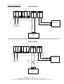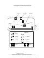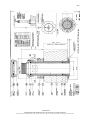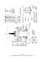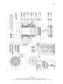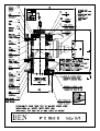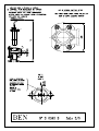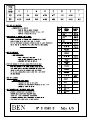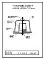
1
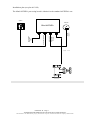
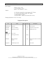
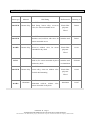
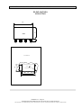
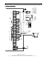
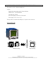
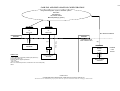
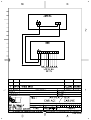
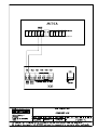
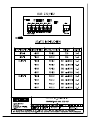
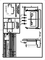
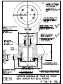
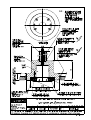
OPERATION AND INSTALLATION MANUAL 03MU002-D 03MU002- D ANTHEA BLIND OPERATION AND INSTALLATION MANUAL This document is i2e DiFFUSiON property and cannot be copied or transmitted without the company's authorization IND. A B C D Author JCN Date 2003 EE EE 11/04/06 27/03/07 Description Initial Version Addition Index modification – Correction scale 32 knots p°4, 23, 24 RGD100 CONNECTING p°22 03MU002- D ANTHEA BLIND OPERATION AND INSTALLATION MANUAL This document is i2e DiFFUSiON property and cannot be copied or transmitted without the company's authorization CONTENTS 1. DESCRIPTION ........................................................................................................................................................................3 1.1 EQUIPMENT DESCRIPTION ................................................................................................................................................3 1.2 MAIN FEATURES ..................................................................................................................................................................6 1.3 TECHNICAL FEATURES ......................................................................................................................................................7 1.4 SENSORS AND HULL FITTING ...........................................................................................................................................8 2. CHOICE OF HULL EQUIPMENT .......................................................................................................................................9 2.1 SCREWED-TO-HULL-FITTING WITH VALVE TYPE 48.1.RVB WITH 48.1.RVB16 SENSOR OR 65.1.RVB WITH 65.2.RVB.20 SENSOR ................................................................................................................................................................11 2.2 WELDED-TO-HULL-FITTING WITH VALVE TYPE 48.1.RVI WITH 48.1RVB. 16 SENSOR OR 65.1.RVI WITH 65.2.RVB.20 SENSOR ................................................................................................................................................................13 2.3 SCREWED-TO-HULL-FITTING WITHOUT VALVE TYPE 48.1.RB OR 48.1.RBL WITH 48.1.RB OR 48.1.RVB SENSOR (DRAWING N° C1285/C1301) .......................................................................................................................................14 2.4 WELDED-TO-HULL-FITTING WITHOUT VALVE TYPE 48.1.RI WITH 48.1.RB SENSOR .........................................15 2.5 LENS PROBE WITH HULLFITTING MADE OF STAINLESS STEEL OR ALUMINIUM ....................................................16 3. INSTALLING THE ELECTRONIC UNIT.........................................................................................................................17 3.1 ELECTRONIC CASES : SIZE AND INSTALLATION........................................................................................................18 3.2 INSTALLING THE ANALOG SPEED AND DISTANCE REPEATER ..............................................................................19 3.3 SUB-SYSTEM CONNECTIONS ..........................................................................................................................................20 3.4 COMBINED SPEED AND DISTANCE REPEATER : INSTALLATION ...........................................................................21 4. TESTS, ADJUSTMENTS AND CALIBRATION UPON FIRST USE.............................................................................23 4.1 LOG CALIBRATION............................................................................................................................................................26 4.2 CALIBRATION OVER SHORT DISTANCES.....................................................................................................................27 4.3 DAMPING ADJUSTMENT ..................................................................................................................................................31 5. USE OF BLIND ANTHEA....................................................................................................................................................32 5.1 LINEARITY ADJUSTMENT................................................................................................................................................32 6. SERIAL OUTPUT NMEA 0183 – IEC 61162-1..................................................................................................................34 6.1 DATA TRANSMISSION......................................................................................................................................................34 6.2 FORMAT OF SENTENCE INFORMATION........................................................................................................................34 6.3 SENTENCE DESCRIPTION.................................................................................................................................................34 DRAWINGS ...............................................................................................................................................................................36 EC TYPE EXAMINATION CERTIFICATE BEN/I2E Marine Distributors 03MU002- D – Page 2 ANTHEA BLIND OPERATION AND INSTALLATION MANUAL This document is i2e DiFFUSiON property and cannot be copied or transmitted without the company's authorization 1. DESCRIPTION ANTHEA BLIND is a new generation of electromagnetic log. For standard operation, it uses model 48mm and LENS flat-surfaced sensors. It can be adapted to other BEN sensors having the same electrical characteristics. ANTHEA BLIND includes an automatic gain adjustment for optimum accuracy and a calibration software facility. A permanent self-test signals any possible log faults on a programming consol. 1.1 EQUIPMENT DESCRIPTION Standard equipment includes : one main cabinet giving the following data : ♦ 1 mile totalizer ♦ 1 daily mile totalizer ♦ 1 RS 422 / 232 NMEA 0183 output (IEC 61162-1) 3 linearization points one 48.1.RVB16 sensor with 16m length cable, retractable at sea. one hull-fitting with valve, 48.1.RVB (retractable-valve-bronze alloy), screw-on type or one hull-fitting with valve, 48.1.RVI (retractable-valve-stainless), weld-on type. One Lens sensor with hull fitting for aluminium or steel hulls 03MU002- D – Page 3 ANTHEA BLIND OPERATION AND INSTALLATION MANUAL This document is i2e DiFFUSiON property and cannot be copied or transmitted without the company's authorization Options : GA 120 analog speed and distance repeater scale - 2 + 16 knots scale - 3 + 24 knots scale - 5 + 25 knots scale 0 + 48 knots scale 0 + 32 knots RGD 100 combined repeater - digital and pseudo-analog speed - covered distance/with reset - covered distance/without reset XY version Available outputs are : − − − − current output 0.500µA which allows to connect an analog speed and distance repeater GA120 type (scale -2/+16 or -3/+24). one 1/10 mile output two 1/200 mile output one RS232 / RS 422 NMEA0183 output (IEC 61162-1) 03MU002- D – Page 4 ANTHEA BLIND OPERATION AND INSTALLATION MANUAL This document is i2e DiFFUSiON property and cannot be copied or transmitted without the company's authorization Installation plan (see plan 6631-M) The blind ANTHEA' processing board is identical to the standard ANTHEA's one. option GA120 Blind ANTHEA Analog repeater alarm output 1/200 mile 1/10 mile analog output RS232/RS422 output Power supply 220V-50Hz/ 60Hz RGD100 Lenght < 70 m 03MU002- D – Page 5 ANTHEA BLIND OPERATION AND INSTALLATION MANUAL This document is i2e DiFFUSiON property and cannot be copied or transmitted without the company's authorization 1.2 MAIN FEATURES Watertight blind cabinet made of a molded alloy, flush mounted. IP 65 watertightness Size : 244 x 164 x 95 mm Programming consol for : - Calibration 3-linearization-point adjustment and setting - Service Error message display Display of : longitudinal speed transversal speed resultant speed drift angle for XY version (optional) Transmitted Data : Digital speed : Covered distance/reset : Scale : Test and alarm 0,1 knot definition 99999,9 -5 or 50 knots Permanent self-test Automatical gain control Accuracy (after calibration) ± 2 % on the LCD display (The results are guaranteed for a depth > 3 meters) For a roll leading to an oscillation of ± 3 Knots of the displayed speed with a period of 4 seconds, the damping function of the equipment reduce this oscillation to a value inferior of ± 0,3 Knots. Variation of the displayed speed according to water temperature is less than 0,2 Knot. Variation of the displayed speed according to water salinity is less than 0,2 Knot. Note : maximum length between sensor and electronic unit = Please refer to drawing “Cabling and installation configuration”. 03MU002- D – Page 6 ANTHEA BLIND OPERATION AND INSTALLATION MANUAL This document is i2e DiFFUSiON property and cannot be copied or transmitted without the company's authorization 1.3 TECHNICAL FEATURES Power supply : 24 Vcc (+ 30 % - 10 %) or 220V 50/60Hz (± 10 %) Option : 110V 50/60 Hz (+/- 10 %) Outputs : 2 x 1/200 mile, potential free contact outputs, 24V, 250mA 1 x 1/10 mile, open collector output, 24V, 500mA 1 x analog output 0 to 500 µA 1 x RS 422/ RS232 - NMEA 0183 format (IEC 61162-1) Damping adjustment via 4-16-32 sec.strap Equipment Description P/N Name Qty Weight Description PVBEN299/07 Main unit 1 4 kg IP65 metal unit PVBEN008 Sensor 48.1RVB16 1 4 kg Retractable with 16m cable PUBEN016 Hull fitting 48.1 RVI 1 5 kg Weldable with valve Options PVBEN299/09 XY version GALV 120 GA120 galvanometer PVBEN295 RGD 100 Digital Filscgp9822 0,5 kg 3 kg Digital speed, distance and alarm repeater repeater 2 shielded pairs cable Sensor cable 03MU002- D – Page 7 ANTHEA BLIND OPERATION AND INSTALLATION MANUAL This document is i2e DiFFUSiON property and cannot be copied or transmitted without the company's authorization 1.4 SENSORS AND HULL FITTING Sensor type Material Hull fitting Hull material Drawing n° Hull fitting, bronze alloy, screw-on, Plastic fiber D0342 48.1.RVB 48.1.RVB Bronze alloy valve, for sensor retractable at sea polyester Wood 48.1.RVI 48.1.RVB Stainless steel, weld-on, with valve, for Stainless steel D0343 Plastic fiber C1301 sensor retractable at sea 48.1.RB 48.1.RB Bronze alloy Screw-on, without valve, for sensor retractable in dry dock polyester Wood LENS LENS weld-on, for sensor retractable by diver Stainless steel with no dry dock or Aluminium F0354M 48.1.RBL 48.1.RVB Bronze alloy bronze alloy, screw-on, without valve, for thick hull mounting Plastic fiber C1285 polyester Wood 48.1.RA 48.1.RA Aluminum Aluminum weld-on, without valve, Aluminum sensor retractable in dry dock 03MU002- D – Page 8 ANTHEA BLIND OPERATION AND INSTALLATION MANUAL This document is i2e DiFFUSiON property and cannot be copied or transmitted without the company's authorization C1287 2. CHOICE OF HULL EQUIPMENT 1. According to vessel size - Hull-fittings with valve (48.1 RVI - 48.1 RVB) or LENS . Are used on all types of vessels - Hull-fittings without valve (48.1 RB - 48.1 RA - 48.1 RBL - 48.1 RI) are used on : . 500 toners maximum . Fishing ships not longer than 45m . Yachts 2. Hull fitting cannot be used in dangerous compartments (fuel, hydrocarbons, chemicals). 3. Hull strength must be checked before installation of hull fitting. 4. Hull fitting must be installed in compliance with the specifications of the ship classification company. 5. Power supply wiring must comply with the specifications of the ship classification company. Sensor location The flush sensor must be installed in the foremost area of the vessel, when possible in a perpendicular position in the lower section of the bulb on the keel line. Deviation from the perpendicular measured in relation to the vessel’s center line is not to exceed 5°. In relation to the port/starboard yaw axis, deviation to a maximum of 30° may be permissible in particularly favorable conditions. The installation position is to be at least 0.5m from echo sounder transmitter and similar devices; The sensor must be positioned at least 10m away from corrosion protection electrodes. The maximum AC voltage component of the supply voltage of active corrosion protection electrodes is not to exceed 20mV eff. The flat sensor surface measures the water speed along the hull. This measured speed is not equal to the vessel's true speed. Measured speed is lower than vessel's speed. At vessel's extreme fore, near true speed is obtained, but towards the aft of vessel speed value differs. The area along the hull where speed is different from vessel's speed is called the "boundary layer". Its thickness increases from fore to aft. The main cause is water running along the hull, which decreases up front. Because of the hull profile, hydrodynamic penetration coefficient is minimum in the fore. Speed does not depend on fouling of the hull located in the boundary layer. Therefore, the ratio of the vessel's speed and measured speed is constant. The sensor must be located near the bow, as far forward as possible. It must always remain immerged (if the sensor emerges occasionally, this can cause a short disturbance which doesn't effect the total distance information). In order to protect the sensor against docking maneuvers, it is recommended to weld two strips on both sides of the sensor close to the hull-casing flanges. In order to avoid hydrodynamic disturbances, it is strongly suggested to profile these strips. Their dimensions will be calculated depending on the desired protection. 03MU002- D – Page 9 ANTHEA BLIND OPERATION AND INSTALLATION MANUAL This document is i2e DiFFUSiON property and cannot be copied or transmitted without the company's authorization The line joining the electrodes of the sensor must be perpendicular to the vessels longitudinal axis. ATTENTION : It is mandatory to install the sensor in a dry area. In case of sustained immersion, it is strongly advised to use a special watertight sensor. For vessels with a bulge bow, the area located within distance equal to twice the height of the bulge can be disturbed. The sensor must be preferably located in the bulge. When it is not possible to install the sensor up front, it is recommended to fix it on a streamlined bulge. For special installation cases (bow thruster...), please contact an I2E/BEN Marine certified agent. When the sensor is to be retracted from inside the hull, which is the general case, make sure that the sensor location is easily accessible, avoiding costly and long operations. Cargo holds, for instance, cannot be considered as accessible ; in this case, an I2E/BEN Marine certified agent will advise you. General rules for sensor installation Before proceeding or drilling, etc. make sure that there is room enough for retraction of the sensor and vital service work. If the hull plating is not flat enough at the selected area, it is necessary to flatten the hull or fit a flattened hull reinforcement. Welding the hull casing to the hull requires special care. For welding to a carbon steel hull, use electrodes in austenitic alloy : 24 Cr, 12 Ni, 3 Mo or 20 Cr, 12 Ni, 3 Mo". Welding will be preferably made in argon atmosphere. All BEN hull-fittings are fitted with a plastic outer cap (part n°16 on drawing D0343). This part is vital and shall be carefully put in place and sticked using tightness cement during installation. If broken, replace it immediately. A spare outer cap is always supplied either with the fitting or with the spares. Fibered plastic or sandwich hulls : plastic hulls are not as resistant to screw pressure as metallic ones. Concerning sandwich hulls, the sandwiched materials must be replaced by a solid wooden ring or the equivalent. On standard plastic hulls, a large surface metallic washer can be placed inside and outside, under the condition that it is covered with plastic material joined smoothly to the hull surface. Tightness between hull and washer must be assured. For this type of hull, the inner part of the drilling must be covered for tightness by self polymerizing polyester. 03MU002- D – Page 10 ANTHEA BLIND OPERATION AND INSTALLATION MANUAL This document is i2e DiFFUSiON property and cannot be copied or transmitted without the company's authorization For wooden hulls, hull thickness (including the reinforcement) must be less than the total thickness the hull-fitting can tolerate. I2E/BEN Marine has developed systems for different thickenesses of hulls. Contact an I2E/BEN Marine agent for further information. Anti-fouling paint must not be removed by abrasion. In certain cases, it is neither possible nor recommended to put the sensor immediately in its working position. In this case, it is necessary to prevent sensor (and connected-cable) damage until it is put in its final position. When installation is over, do not forget to clean the sensor. 2.1 SCREWED-TO-HULL-FITTING WITH VALVE TYPE 48.1.RVB WITH 48.1.RVB16 SENSOR OR 65.1.RVB WITH 65.2.RVB.20 SENSOR (Drawing n° D0342) Steel hulls may be too thin and require suitable reinforcement : minimum total thickness must be 25 mm. Check that actual thickness of the hull (including the reinforcement) is less than the tolerated thickness. Note : Reinforcement is always recommended on any type of hull. 1. Remove the sensor from the hull-fitting and from piece (16). Remove the 0-rings. 2. Drill a 64.5 mm diameter hole in the hull for 48 sensors or 93 mm diameter hole for 65 sensors. Remember to flatten external surface in order to get a perfect bearing of piece (1). For plastic hull, take into acount the instruction § “ General rules for senser installation ”. Do an external chanfer (about 5 mm - 45°) for easy mounting and proper positioning of piece (1). Safety of the vessel deperds from Installation. 3. Position hull casing (1) and use self polymerizing mastic for tightness (rubber, silicone rilsan for example). Mastic layer must be thin. Let is harden to a pasty consistency. 4. Screw casing nut (2) on hull casing, and torque it with hammer or caulking tool. To avoid the hull casing from unscrewing, block it with a wedge. 03MU002- D – Page 11 ANTHEA BLIND OPERATION AND INSTALLATION MANUAL This document is i2e DiFFUSiON property and cannot be copied or transmitted without the company's authorization 5. Screw the four thru-bolts ref (3) into the nut threaded holes (piece ref. 2) and butt them firmly against the hull plating in order to prevent future unscrewing of the nut. Safety is increased if a blind hole of a few mm depth is drilled facing the bolt. For plastic hulls, it is recommended to glue the nut to the hull with polymerizing fibered polyester. 6. Clean and grease 0-rings (11) an (12). Put them in place. Install the gate valve and properly adjust it (with regard to thru-bolt ref.3). 7. Put the upper 0-ring (6) in place in its landing, suitably greased. Install the upper flange (5). 8. Screw the safety nuts (19) on thru-bolt (3) forcing moderately and equally. 9. Put 0-ring (13) in place. 10.Fill the inner part of outer bush (16) with self polymerizing silicone rubber such as "syntofer". Remember to fill only the part indicated on D0342 drawing. 11.Introduce isolating part ref (16) with force. Make sure that it is properly positioned. Check that nothing protrudes and try to introduce the sensor from the outside. Let the mastic harden. 12.Grease flat seal (7) and put it in place. 13.Carefully lubricate the sensor and introduce it in its proper location. Take care to not grease the electrode. 14.Use grease supplied with spares. When properly positioned, the sensitive surface of the sensor protrudes at least 1 mm from external bush, and the red mark on the sensor head is directed towards the bow. 15.Fix sensor flange (8) with screws (9) and washers (20) ; put circlip 15. Connect the link (10). Check link length : it must be long enough to allow closing of the valve and short enough to prevent sensor from escaping and passing over 0-ring (6). When using anti-fouling paint, DOT NOT PAINT THE ELECTRODES - DO NOT GREASE THE LECTRODES Note : to avoid sensor damage, it is recommended to put sensor in place just before departure, or while at sea (in this case, do not forget to close the valve). 03MU002- D – Page 12 ANTHEA BLIND OPERATION AND INSTALLATION MANUAL This document is i2e DiFFUSiON property and cannot be copied or transmitted without the company's authorization 2.2 WELDED-TO-HULL-FITTING WITH VALVE TYPE 48.1.RVI WITH 48.1RVB. 16 SENSOR OR 65.1.RVI WITH 65.2.RVB.20 SENSOR (Drawing n° D0343) Drill a 77 mm diameter hole in the hull for 48 sensors and a 92 mm diameter hole for 65.2 sensors. Do an external chamfer of 5 mm (45°) for welding. Prior to weld in the hull casing (1) the hull fitting is to be fully dismantled and O-rings are to be taken off. 1. Hull-casing (1) must be properly positioned, follow suggested procedure on drawing C1287. Weld the hull-fitting to he hull. After three or four spots have been welded on the internal side of the hull, remove the tools. Check that the lower part of hull-casing (1) does not protrude the hull, and grind the external seam flush with the hull. IMPORTANT : Hull-fitting mechanical tolerances are very precise. In order to avoid any possible damage, do not heat the hull-fitting when welding it. 2. Weld piece ref (2) on hull-casing (1). 3. Weld the four try-bolts (3) on lower flange (2) - might already be done in factory 4. Clean and oil up bearing surface of 0-ring (11) and (12). Put them in place. Install and position the gate valve (4). 5. Put 0-ring (6) and position upper flange (5). 6. Screw nuts (19) - do not forget the washers (18) - on the thru-bolts (3). 7. Put the lower 0-ring seal ref (13) in place. Fill the inner part of the outer bush ref (16) with self polymerizing silicone rubber. Be careful to not over fill. Force the isolating part inside and clips it. Check positioning of hull-casing and also check that nothing protrudes inside by carefully introducing the sensor. Let the paste harden the time required. 8. Put flat seal (7) in place. Carefully lubricate the sensor and introduce it. Use grease supplied with spares. 9. When properly positioned, the sensitive surface of the sensor protrudes at least 1 mm from external bush, and the red mark on the head is directed towards the bow. 10. Fix sensor flange(8) with screws (9) and washers (20) ; put circlip 15. 11. Connect the link (10). Check link length : it must be long enough to allow closing of the valve and short enought to prevent sensor from escaping and passing over 0-ring (6). To avoid sensor damage, it is recommended to put sensor in place just before departure, or while at sea (in this case, do not forget to close the valve). When using anti-fouling paint. DO NOT PAINT THE ELECTRODES - DO NOT GREASE THE ELECTRODES 03MU002- D – Page 13 ANTHEA BLIND OPERATION AND INSTALLATION MANUAL This document is i2e DiFFUSiON property and cannot be copied or transmitted without the company's authorization 2.3 SCREWED-TO-HULL-FITTING WITHOUT VALVE TYPE 48.1.RB OR 48.1.RBL WITH 48.1.RB OR 48.1.RVB SENSOR (Drawing n° C1285/C1301) Above fittings are in bronze (48 RB) or in aluminum (48 RA) according to the sensor material (C1287). Those fittings are convenient for hulls not over 30 mm thickness, including hull reinforcement. Minimum clearance for sensor retraction is 150 mm distance from inside hull. For thick hulls, a longer hull-fitting has been designed (see drawing C1285 ; 48 RBL hullfitting). This hull-fitting concerns only wooden vessels. Maximum thickness of the hull is 110 mm. Minimum clearance for sensor retraction is 410 mm. A threaded cap ref (25) is supplied with the hull-fitting in order to obturate the opening when the sensor is removed. 1. Drill a 64.5 mm diameter hole in the hole for 481 sensors. Remember to flatten external surface in order to get a perfect bearing of piece (1). Do an external chamfer (about 5 mm 45° -) for easy mounting and proper positioning. 2. Position hull-casing (1). Tightness is obtained by a self polymerizing silicone rubber in order to prevent rotation of the body when unscrewing. 3. Fill the inner part of outer bush ref (16) with the mastic mentioned above. Be careful to fill only the part indicated on drawing C1301. Force the bush, check that the bush is properly clipsed and that nothing protrudes. Test the clearance by introducing the sensor preferably from outside. Let the paste harden. 4. Put the washer (24) and the nut (23). The nut (23) must be locked by a conventional mechanical system (refer to the drawing). As to the RBL hull-fitting, it is possible to add a second nut acting as a lock-nut (see drawing C1285). 5. Position 0-ring (13) - previously greased - and flat seal (7) and carefully introduce the sensor. Take care to not grease the electrode. Use grease supplied with spares. When using anti-fouling paint, DO NOT PAINT THE ELECTRODES. Attention : Red mark on sensor-head must be directed towards the bow. 6. Screw sensor nut (8). Do not forget the circlips (15). DO NOT GREASE THE ELECTRODES 03MU002- D – Page 14 ANTHEA BLIND OPERATION AND INSTALLATION MANUAL This document is i2e DiFFUSiON property and cannot be copied or transmitted without the company's authorization 2.4 WELDED-TO-HULL-FITTING WITHOUT VALVE TYPE 48.1.RI WITH 48.1.RB SENSOR (Drawing n° C1287) 1/ Drill a 77 mm diameter hole in the hull. Do an external chamfer of 5 mm (45°) for welding. 2/ Position hull-casing (1). To obtain accurate positioning, follow suggested procedure on the drawing. After three or four spots have been welded on internal side of hull, remove the mechanical system and check the positioning. Hull-casing must be flush with the hull. After welding, grind the external seam on a level with hull surface in order to allow piece (16) to butt on piece (1). IMPORTANT : Hull-fitting mechanical tolerances are adjusted. In order to avoid any destroying risk, do not heat the hull-fitting when welding it. 3/ Fill the inner part of outer bush ref (16) with self polymerizing silicone rubber. Fill only the part indicated on the drawing. Replace the bush, check that bush is properly clipsed and that nothing protrudes. Test the clearance by introducing the sensor preferably from outside. Let the paste harden. In most cases, lower flange (2) is already welded to hull casing (1). 4/ Weld the thru-bolts (3). 5/ Grease 0-ring (13) and position it. 6/ Do not forget flat seal (7). Introduce and grease the sensor. Install sensor-flange (8). Screw the thru-bolts with (19) + (18). Do not forget circlips (15). Attention : To introduce sensor, use grease supplied with spares. When using antifouling paint, DO NOT PAINT THE ELECTRODES, DO NOT GREASE THE ELECTRODES. When properly positioned, the sensitive surface of the sensor protrudes at least 1 mm from external bush. The red mark on the sensor head is directed towards the fore of the vessel. 03MU002- D – Page 15 ANTHEA BLIND OPERATION AND INSTALLATION MANUAL This document is i2e DiFFUSiON property and cannot be copied or transmitted without the company's authorization 2.5 LENS PROBE WITH HULLFITTING MADE OF STAINLESS STEEL or Aluminium A/ INSTALLATION PROCEDURE 1. Drill a 184mm hole in the hull. Do an external chamfer of 5mm (45°) for welding. 2. Position hull-fitting in the correct mounting direction. The reference mark drawn on hull-fitting is oriented towards bow, it must be exactly parallel to the vessel axis. The hull-fitting defines the mounting direction of the lens probe. When the hull-fitting is welded, grind the external seam on a level with hull surface in order not to create hydraulic interferences around the probe. 3. Weld a steel pipe to back of hull-fitting. Ø = 40mm - Thickness = Minimum 5mm This pipe will be stopped at 50mm above maximum waterline. 4. Introduce the probe after pulling watertight cable into the pipe. 5. Brush probe bottom with watertight rubber before fixing it with its 4 screws. Caution : DO NOT GREASE THE ELECTRODES. When using anti-fouling paint, DO NOT PAINT THE ELECTRODES. B/ DISMOUNTLING AND CHANGING OF SENSOR 1/ Cut off power supply of the electronic. 2/ Disconnect the watertight cable sensor from the electronic. 3/ Strongly attach the watertight cable to a rope of at least the lenght of pipe. 4/ Send a diver to unscrew the four fixation screws of sensor. 5/ Screw-up the two extraction screws in order to push out the sensor from its hullfitting. 6/ Extract the complete defective sensor with its watertight cable and the rope attached to it. 7/ Strongly attach the new sensor’s watertight cable to the rope and pull back up the cable for a new connection. Caution : Before replacing the sensor in its hullfitting, don't forget to apply the watertight o'ring by silicone mastic. This equipment is DNV and GL typed approved. 03MU002- D – Page 16 ANTHEA BLIND OPERATION AND INSTALLATION MANUAL This document is i2e DiFFUSiON property and cannot be copied or transmitted without the company's authorization 3. INSTALLING THE ELECTRONIC UNIT The BLIND ANTHEA can be flush mounted on to the bulkhead at any angle attached with 4 screws. ◊ The cover of the BLIND ANTHEA is hinged. Leave enough space on the left side for opening. ◊ After terminal connecting, pull out as many wires as possible before tightening stuffing boxes in order to limit HF radiations inside unit. ◊ If wires are hardened, they should not be hardened beyond stuffing boxes input and should be grounded to casing via stuffing boxes. The equipment is designed for a battery power supply of 24 volts -10% +30%. Its average consumption is 200 mA. The BLIND ANTHEA is protected against polarity reversal of the power supply ; if it does not work, reverse the wires. The sensor cable is 16 meters long. For greater lengths (up to 150 m), use two junction boxes and two separate shielded cables (see drawing on next page). For a 24 V power supply, the value of the fuse is 1A. For a 220 V power supply, the value of the fuse is 125mA. 03MU002- D – Page 17 ANTHEA BLIND OPERATION AND INSTALLATION MANUAL This document is i2e DiFFUSiON property and cannot be copied or transmitted without the company's authorization 3.1 ELECTRONIC CASES : SIZE AND INSTALLATION BLIND ANTHEA MOUNTING 164 244 50 BLIND ANTHEA 130 150 FLUSH-MOUNTING 4 holes 4,5 226 335 03MU002- D – Page 18 ANTHEA BLIND OPERATION AND INSTALLATION MANUAL This document is i2e DiFFUSiON property and cannot be copied or transmitted without the company's authorization 3.2 INSTALLING THE ANALOG SPEED AND DISTANCE REPEATER The speed and distance repeater is a wide-angle galvanometer with a waterproof front surface. It can be placed on an outside panel. The rear part of this panel however, must be protected from water projections. This repeater also has a 12V - 35 mA lighting. Power supply comes from the ANTHEA. 97 ANALOG SPEED AND DISTANCE REPEATER GA120 110 72 GA120 (Front view) GA120 CONNECTIONS ANTHEA Cabinet GA120 (Back view) 20 Light 21 23 22 11 Signal - + Totalizer 12 03MU002- D – Page 19 ANTHEA BLIND OPERATION AND INSTALLATION MANUAL This document is i2e DiFFUSiON property and cannot be copied or transmitted without the company's authorization Power supply 24V DC ou 220V AC 1 2 3 4 6 TRX 5 0 7 t 144 8 9 11 RGD 100 REPEATER (option) 144 14 1/200 MN 13 1/200 MN contact (x2) 12 + - Totalize r 1/ 10NM 2 alarm contact 10 alar contac m t RS232/RS422 RS232/RS422 alar m contac output 15 1/200 MN 16 18 I 2 Totalizer 17 I 1 Inductor s 19 bL 20 22 - 23 - + 0-500µA repeater signals 24 + 25 26 Lighting Analog Speed and Distance display GA120 21 Lighting 29 E2 sensor 28 E1 Inductor I1 = 17= black Inductor I2 = 18 = blue Inductor hardening : 19 Electrode E1 = 28 = red Electrode E2 = 29 = white Electrode hardening = 27 27 BL Electrodes 3.3 SUB-SYSTEM CONNECTIONS ANTHEA CONNECTIONS 03MU002- D – Page 20 ANTHEA BLIND OPERATION AND INSTALLATION MANUAL This document is i2e DiFFUSiON property and cannot be copied or transmitted without the company's authorization 3.4 COMBINED SPEED AND DISTANCE REPEATER : INSTALLATION The repeater is a 144 x 144 mm watertight case. It shows : Digital and pseudo-analog speed 1/20 knot definition Distance/reset : 1/10 mile definition Log status (test - alarms) Reset and brightness control are on front panel Power supply : 24V -10 % to 30 % Wiring is made via terminal and stuffing box, 5 repeaters can be connected RGD100 REPEATER 144 200 165 138 138 144 30 150 3 holes Bracket mounting 4,5 Flush mounting 03MU002- D – Page 21 ANTHEA BLIND OPERATION AND INSTALLATION MANUAL This document is i2e DiFFUSiON property and cannot be copied or transmitted without the company's authorization RGD100 CONNECTING RGD100 RS232 (Option) Current Output J4 220V 24V J3 GALVA J2 OV RX J1 0V TX RXB RXA TXB TXA Tx 220V AC or 24V DC Tx J2 2 REPEATER 1 0v Rx 0v Rx 5 0v 0v 6 ANTHEA RS232 RGD100 RS422 (Option) Current Output J4 220V 24V J3 GALVA J2 OV RX RXB RXA J1 0V TX TXB TXA Tx 220V AC or 24V DC Tx J2 2 1 RXB RXA RXA RXB 5 0v 0v 6 ANTHEA RS422 03MU002- D – Page 22 ANTHEA BLIND OPERATION AND INSTALLATION MANUAL This document is i2e DiFFUSiON property and cannot be copied or transmitted without the company's authorization REPEATER 4. TESTS, ADJUSTMENTS AND CALIBRATION UPON FIRST USE Preliminary tests Once installation is completed, a first test must be performed before turning the power on. Open the BLIND ANTHEA and move the Normal - Test switch (S1) to the Test position. Turn the button clockwise to turn the device on. If nothing appears on the speed repeater, this means that the ANTHEA is not receiving any current. Check the battery charge, then the fuse. When working, the log is at about 80 % of the scale in Test mode. In case a GA120 galvanometer is used, make sure that strap position corresponds to the galvanometer scale, that is : E6 E5 E4 E3 - 2 + 16 knots - 3 + 24 knots 0 + 32 knots 0 + 48 knots 03MU002- D – Page 23 ANTHEA BLIND OPERATION AND INSTALLATION MANUAL This document is i2e DiFFUSiON property and cannot be copied or transmitted without the company's authorization BLIND ANTHEA BOARD STRAP POSITIONS Zero adjustment R57 Gain adjustment Zero and gain adjustment strap R56 E11 Damping Selection RS232/RS422 Current outpu scale E21 E22 Normal Test Fuse Current output scale Damping Damping 32 seconds - 2 + 16 knots Damping 16 seconds - 3 + 24 knots Damping 4 seconds 0 + 32 knots 0 + 48 knots RS232/422 OUTPUT RS232 E21 E22 RS422 E21 E22 03MU002- D – Page 24 ANTHEA BLIND OPERATION AND INSTALLATION MANUAL This document is i2e DiFFUSiON property and cannot be copied or transmitted without the company's authorization Zero adjustment When ship is motionless on dead calm water, speed can be above zero. You then have to correct this zero shifting. Make sure there is no undertow. You can easily check it by putting sensor back to front to check zero does not change. If it does, zero can be adjusted by equalizing absolute speed values when sensor is in normal position and is back to front. Do not forget then to put sensor back in correct position (red mark towards ship bow). Zero adjustment process E15 Put strap E11 E13 Adjust with R57 potentiometer E12 Once adjustment has been archieved, E11 take strap E11 off so as to set it Gain adjustment process Switch "TEST" mode on, and wait a few seconds till speed stabilizes. Note test value. Calculate new test value, i.e. : Example : Indicated speed on "TEST" position is 20 knots and we want to correct gain by -0,8 %. 20.0 x 0,8 = 19,84 knots 100 Gain adjustment process Gain adjustment process E15 Strap E11 E13 Adjust gain with R56 potentiometer E12 Once gain has been adjusted, take strap E11 off, so as to set adjustment E11 Switch to "NORMAL" position. 03MU002- D – Page 25 ANTHEA BLIND OPERATION AND INSTALLATION MANUAL This document is i2e DiFFUSiON property and cannot be copied or transmitted without the company's authorization 4.1 LOG CALIBRATION An E/M log measures speed and distance in relation to water. When there is no current, the distance indicated by the log is the distance in relation to the bottom or the true distance. Several methods can be used : a) Empirical method Using the average of the measurements of long distances covered in comparison with the actual distances. b) Rational method Using the measurements of speed in covering the same base distance several times. The device is set for the average sensitivity of its sensors in the factory. If the first method is used, calculate the average relative error for a certain number of runs at different times and with different tide levels, but at roughly the same speed. It is convenient to calculate these errors in percentages. The average error is calculated by taking the average of the relative errors. A large enough number of runs must be made, as in the following tables : Runs listed by order Error 1 2 3 4 5 6 7 8 9 10 - 2% - 5% + 7% - 6% + 2% + 1% + 4% + 3% + 1% + 3% -2-5+7-6+2+1+4+3+1+3=+8 The average relative error is 8 = + 0,8 % 10 The correction is : - 0,8 % 03MU002- D – Page 26 ANTHEA BLIND OPERATION AND INSTALLATION MANUAL This document is i2e DiFFUSiON property and cannot be copied or transmitted without the company's authorization 4.2 CALIBRATION OVER SHORT DISTANCES It is possible to calibrate the log with precision by covering a known base distance defined by alignment on the shore, preferably following a route defined by an alignment. Calculating true or real speed : Clock the time needed to cover the base distance : the true or real speed Vr is : Vr = Dr x 3600 Tr Dr = Real distance covered Tr = Time taken to cover the distance in seconds The factor 3600 comes from the fact that the speed is measured in knots (miles per hour) and the time in seconds. Calculation of the log speed The log speed must not be read on the speed display as the measurement would not be precise enough. The average speed must be determined by clocking the time taken to complete the distance. A second stop watch is useful, but if you only have one, the same method can be used by taking the times on the first stop watch as you go. With a second stop watch, measure the time taken to cover the distance displayed on the distance counter. Start the stop watch as soon as the first one tenth of a mile figure changes after entering the base distance zone. Stop the stop watch when the base distance has been covered or just before reaching the end of the distance when the one tenth of a mile figure changes. Do not change the speed or the direction of the boat until this measurement has been taken. Log speed VI is : V1 = D1 T1 x 3600 Let Dd and Df respectively be the distances displayed at the beginning and at the end of the trip ; the distance displayed on the log will be : D1 = Df - Dd If the time measured between the display of Dd and Df is T1, the average speed indicated on the log is : V1 = D1 T1 03MU002- D – Page 27 ANTHEA BLIND OPERATION AND INSTALLATION MANUAL This document is i2e DiFFUSiON property and cannot be copied or transmitted without the company's authorization Tr and T1 are not identical, since the beginning and the end of each of these timings are not identical. If the base distance is long enough to be able to accept an approximation of a tenth of a mile, just not the indications on the distance counter upon entering and leaving the base distance zone. The above measurements are to be taken over several runs. a) When in a zone where the current remains constant throughout the tests, the base distance zone should be covered a second time in the opposite direction, carrying out the same operations. The average of the speeds obtained is then calculated : Vaverage = V1 + V2 2 b) If the current is not constant, a third run in the same direction as the first will be made, as long as the tests are made consecutively with no time out between any two test runs. The average is calculated as follows : Vaverage = V1 + 2V2 + V3 4 V1 = speed calculated on the first run V2 = speed calculated on the second run V3 = speed calculated on the third run Always try to operate at the speed given by the log, modifying the engine speed controls if necessary. Do not perform the measurements while the tide is turning. Having found the average real speeds and the average log speeds, a simple calculation will provide the percentage of error of the log. The percent error is : 100V1 + Vr V1 This error may be positive or negative. Example : suppose that 1.1 miles are covered in a clocked time of Tr1 = 364 seconds. 03MU002- D – Page 28 ANTHEA BLIND OPERATION AND INSTALLATION MANUAL This document is i2e DiFFUSiON property and cannot be copied or transmitted without the company's authorization The real speed will be : 1,1 x 3600 = 10,9 knots 364 The average real speed will be : 10,1 + 10,9 = 10,5 knots 2 Suppose that during the first run over the base distance, the stop watch was started when the distance counter was at : 24.1 miles, and that it was stopped when the distance counter was at : 25.4 miles, the stop watch will have run 400 seconds. The distance read from the distance counter will be : 25.4 - 24.1 = 1.3 mile. Calculating the indicated speed gives : 1,3 x 3600 = 11,7 knots 400 During the second run the stop watch was started when the distance counter was at 26.0 mile and stopped when the distance counter was at 27.2 miles, the stop will have run 372 seconds. The distance read from the distance counter is : 27.2 - 26 = 1.2 miles. The speed calculated is : 1,2 x 3600 = 11,6 knots 372 The average value of the speeds indicated is : 11,7 + 11,6 = 11,65 knots 2 Error correction : First evaluate the error in percentage. In the above example, the error : 100 x (11,65 - 10,5) = + 10 % 11,65 The correction to be made is therefore : - 10 %. 03MU002- D – Page 29 ANTHEA BLIND OPERATION AND INSTALLATION MANUAL This document is i2e DiFFUSiON property and cannot be copied or transmitted without the company's authorization Switch "TEST" on and wait a few seconds till speed display is stabilized. Note test value. Calculate new test value : for example : Test value = 18 knots New value = 18 knots - 18 x 10 = 16,2 knots 100 E15 Put-on strapp E11 E13 E12 E11 Adjust potentiometer R56 so as to bring test value back to 16,2 knots. E15 Take off strapp E11 so as to set adjustment E13 E12 E11 Switch on "Normal" position (N). 03MU002- D – Page 30 ANTHEA BLIND OPERATION AND INSTALLATION MANUAL This document is i2e DiFFUSiON property and cannot be copied or transmitted without the company's authorization 4.3 DAMPING ADJUSTMENT Three damping possibility are available : 4s, 16s, 32s. E10 E9 E8 E7 Damping 32s E10 E9 E8 E7 Damping 16s E10 E9 E8 E7 Damping 4s 03MU002- D – Page 31 ANTHEA BLIND OPERATION AND INSTALLATION MANUAL This document is i2e DiFFUSiON property and cannot be copied or transmitted without the company's authorization 5. USE OF BLIND ANTHEA 5.1 LINEARITY ADJUSTMENT SPECIAL PROGRAMMING CONSOLE FOR BEN E/M LOGS CALIBRATION 1/ Connect the Programming console on the Anthea log RS232 output (Sub D9 Connector P2) 2/ At first, all the calibration points are at zero. Proceed with the speed calculations to determine an error curve (true speed/sensor speed). Example : True speed (in knots) Display speed (in knots) 10.4 18.2 26.1 11.5 19.4 27.6 Enter correction couples 03MU002- D – Page 32 ANTHEA BLIND OPERATION AND INSTALLATION MANUAL This document is i2e DiFFUSiON property and cannot be copied or transmitted without the company's authorization Display on Prog. consol Press Action Adjust 1st linearization point (log speed) *1 Log speed xx.x 1 Log speed 10.4 ENTER 10.4 PRESS ENTER ENTER 11.5 PRESS ENTER ENTER 18.2 PRESS ENTER ENTER 19.4 PRESS ENTER Adjust 1st linearization point (true speed) * 1 True speed xx.x 1 True speed 11.5 Adjust 2nd linearization point (log speed) * 2 Log speed xx.x 2 Log speed 18.2 Adjust 2nd linearization point (true speed) * 2 True speed xx.x 2 True speed 19.4 Adjust 3rd linearization point (log speed) *3 Log speed xx.x 3 Log speed 26.1 ENTER 26.1 PRESS ENTER Adjust 3rd linearization point (true speed) *3 True speed xx.x 3 true speed 27.6 ENTER 27.6 PRESS ENTER 0 knots corresponds to zero correction. If all the values have been correctly programmed, the programming console displays : OK to confirm that all the parameters have been taken into account. 03MU002- D – Page 33 ANTHEA BLIND OPERATION AND INSTALLATION MANUAL This document is i2e DiFFUSiON property and cannot be copied or transmitted without the company's authorization 6. SERIAL OUTPUT NMEA 0183 – IEC 61162-1 6.1 DATA TRANSMISSION baud rate 4800 data bits 8 ( D7 = 0) , parity none stop bits 1 6.2 FORMAT OF SENTENCE INFORMATION Version single axis: $ V M V H W , , , , , x x x . x x , N , , * h h <CR> <LF> $ V M V L W , x x x x x . x , N , x x x x x . x , N * h h <CR> <LF> $ P B E N , 0 1 , a a a a * h h <CR> <LF> Version dual axis : $ V M V H W , , , , , x x x . x x , N , , * h h <CR> <LF> $ V M V L W , x x x x x . x , N , x x x x x . x , N * h h <CR> <LF> $ P B E N , 0 1 , a a a a * h h <CR> <LF> $ V M V B W , x x x . x x , x x x . x x , A , , , V , , V , , V * h h <CR> <LF> 6.3 SENTENCE DESCRIPTION --. Water speed and heading $ V M V H W , , , , , x x x . x x , N , , * h h <CR> <LF> $ V M V H W : Start of sentence and identifier x x x . x x : longitudinal water speed in Knots N : Knots hh : Cheksum message recurrence 0.5 second 03MU002- D – Page 34 ANTHEA BLIND OPERATION AND INSTALLATION MANUAL This document is i2e DiFFUSiON property and cannot be copied or transmitted without the company's authorization --. Dual ground / water speed $ V M V B W , x x x . x x , y y y . y y , A , , , V , , V , , V * h h <CR> <LF> $ V M V B W : Start of sentence and identifier x x x . x x : Longitudinal water speed , knots y y y . y y : Transversal water speed, knots A : data valid , V : data invalid hh : Cheksum message recurrence 0.5 second -- Distance travelled through the water $ V M V L W , x x x x x . x , N , y y y y y . y , N* h h <CR> <LF> $ V M V L W : Start of sentence and identifier x x x x x . x : Total cumulative distance, nautical miles y y y y y . y : Distance since reset, nautical miles N: nautical miles hh : Cheksum message recurrence 1 second -- Proprietary sentences $ P B E N , 0 1 , a a a a * h h <CR> <LF> $ P B E N , 0 1 , : Start of sentence and identifier a a a a : alarms hh : Cheksum message recurrence 1 second 03MU002- D – Page 35 ANTHEA BLIND OPERATION AND INSTALLATION MANUAL This document is i2e DiFFUSiON property and cannot be copied or transmitted without the company's authorization 36-B DRAWINGS N° Cabling and installation configuration C1285 Probe 48.1 RVB/hullfitting 48.I RBL C1287 Probe 481 RA/hullfitting 48.1 RA Probe 481 RB/hullfitting 48.1 RI C1301 Probe 481RB/hullfitting 48.1 RB D0342 Probe 48.1 RVB/hullfitting 48.1 RVB Probe 65.2 RVB/hullfitting 65.1 RVB D0343 Probe 48.1 RVB/hullfitting 48.1 RVI Probe 65.2 RVB/hullfitting 65.1 RVI 11850-C BSR Cabling F0189-C DOB Connection F0256-C DOB Configuration F0344-M DOB 232/422 Outlines and mounting 6631-M Blind ANTHEA : size and installation 7851-M “ Lens ” sensor and hullfitting F0354-M “Lens” sensor and Aluminium hullfitting 03MU002-D ANTHEA BLIND OPERATION AND INSTALLATION MANUAL This document is i2e DiFFUSiON property and cannot be copied or transmitted without the compagny's authorization 37-B CABLING AND INSTALLATION CONFIGURATION Integrated Navigation system, stabilizer system. SAT NAV AUTOPILOT TM, ARPA radars BEN Repeater(s) (option) OUTPUTS OUTPUTS Standard or blind unit Standard or blind unit No distance limitation BRIDGE CABLES TYPE : CABLE(3) SENSOR J/B HULL FITTING/ SENSOR (1) One cable with 2 individually shielded pairs (Min=0,34°) (2) According output type (3) Sensor cable is supplied by BEN/I2E : - 16 or 32m - other on request Note : For mechanical protection, we advise the use of armoured (braid) cables. 03MU002-D ANTHEABLIND OPERATION AND INSTALLATION MANUAL This document is i2e DiFFUSiON property and cannot be copied or transmitted without the compagny's authorization (2) OUTPUTS BLIND UNIT CABLE(3) HULL FITTING/ SENSOR CONFIGURATION FOR LARGE SHIPS SENSOR CABLE (3) (1) 70 m max. SENSOR BRIDGE HULL FITTING/ SENSOR Installed near sensor 38-B 03MU002-D ANTHEA BLIND OPERATION AND INSTALLATION MANUAL This document is i2e DiFFUSiON property and cannot be copied or transmitted without the compagny's authorization 39-B 03MU002-D ANTHEA BLIND OPERATION AND INSTALLATION MANUAL This document is i2e DiFFUSiON property and cannot be copied or transmitted without the compagny's authorization 40-B 03MU002-D ANTHEA BLIND OPERATION AND INSTALLATION MANUAL This document is i2e DiFFUSiON property and cannot be copied or transmitted without the compagny's authorization BEN/I2E MARINE AGENTS / DISTRIBUTORS SNEE Bordeaux France Tel 05 56 39 24 40 Fax 05 56 50 23 10 SEDAM Lorient France Tel 02 97 37 11 13 Fax 02 97 37 53 81 FURUNO DK* Hvidovre-Copenhagen Denmark Tel +45 36 77 45 00 Fax +45 36 77 45 01 R.H. GREECE* Piraeus Greece Tel +30 210 411 0260 Fax +30 210 417 7784 SYBERG Maritim* Oslo Norway Tel +47 23 03 75 00 Fax +47 23 03 75 05 MARINE Technics St Petersburg Russia Tel +7 812 332 32 42 Fax +7 812 332 32 34 R.H. USA* Long Beach U.S.A. Tel +1 562 595 0039 Fax +1 562 988 0236 R. H. Hong Kong Kwai Chung, N.T. Hong Kong Tel +852 2 423 90 07 Fax +852 2 480 58 98 CRM Boulogne Sur Mer France Tel 03 21 30 45 13 Fax 03 21 30 45 06 CRM St Malo France Tel 02 99 82 68 43 Fax 02 99 82 28 02 AND Group Tyne & Wear England Tel +44 870 444 9681 Fax +44 870 444 9680 ELCON Reykjavik Iceland Tel +354 561 9510 Fax +354 561 8281 ESCORT LTD* Szczecin Poland Tel +48 91 462 4379 Fax +48 91 462 4408 BORA SPARE Parts Istanbul Turkey Tel +90 216 383 7755 Fax +90 216 383 7766 SOREMAR Casablanca Morocco Tel +212 22 40 50 50 Fax +212 22 24 82 36 JASON Electronics Singapore AEMI Caen France Tel 02 31 35 44 47 Fax 02 31 82 47 02 THEMYS Marseille France Tel 04 42 32 99 05 Fax 04 42 32 94 95 MERE Electroonik Tallinn Estonia Tel +372 6102 048 Fax +372 6102 248 BARRY Electronics Killybegs Co. Donegal Ireland Tel +353 74 97 31215 Fax +353 74 97 31739 ENAMOR Gdynia Poland Tel +48 58 661 6363 Fax +48 58 621 8486 TRANSAS Nikolaev Ukraine Tel +380 512 507 116 Fax +380 512 507 117 PERTEC Cape Town South Africa Tel +27 21 511 50 55 Fax +27 21 511 50 22 R. H. Singapore* Singapore CRM Concarneau France Tel 02 98 97 09 65 Fax 02 98 97 80 83 Marseille MARINE Marseille France Tel 04 91 91 31 42 Fax 04 91 91 69 46 INSALKO AB Helsinki Finland Tel +358 90 685 3860 Fax +358 90 685 3870 HANZA Elektronika Riga Latvia Tel +371 70 20 459 Fax +371 73 20 772 NAUTEL Sistemas Lisboa Portugal Tel +351 21 392 0940 Fax +351 21 392 0949 MARCOM Watson Tasmania Australia Tel +61 3 6331 2711 Fax +61 3 6331 6332 R. H. South Africa Durban South Africa Tel +27 31 20 55 309 Fax +27 31 20 55 541 SAAB Rosemount Singapore ST GUE Concarneau France Tel 02 98 97 50 86 Fax 02 98 50 75 57 Electr. Equipements Montivilliers France Tel 02 32 79 29 60 Fax 02 35 20 82 75 ELNA Rellingen Germany Tel +49 4101 301 218 Fax +49 4101 301 214 R.H. NEDERLAND* Rotterdam The Netherlands Tel +31 10 428 3344 Fax +31 10 428 1498 RMI SA* Madrid Spain Tel +34 913 587 450 Fax +34 917 360 022 MARINE Navaid S. Sydney Australia Tel +61 2 9700 1566 Fax +61 2 9700 1756 AERADIO Technical Manama Bahrain Tel +973 727 790 Fax +973 727 811 NAVICOM* Pusan Korea Tel +82 51 442 4555 Fax +82 51 442 6316 CEGELEC Dieppe France Tel 02 35 06 89 24 Fax 02 35 06 89 50 ETNA Octeville/Mer France Tel 02 35 54 60 60 Fax 02 35 54 60 69 HDW HAGENUK Hamburg Germany Tel +49 40 899 720 Fax +49 40 899 72199 SAM Electronics* Rotterdam The Netherlands Tel +31 10 479 5444 Fax +31 10 479 5545 RMI SA Cadiz Spain Tel +34 956 277 123 Fax +34 956 251 757 WRIGHT Techno Albany Auckland New Zealand Tel + 649 4760 284 Fax +649 4760 281 ZENER Electronics Dubai U.A.E Tel +971 4352 2880 Fax +971 4352 4410 AMI GFV Busan Korea Tel + 8251 414 9933 Fax +8251 414 9931 NAVELEC Le Havre France Tel 02 35 24 09 05 Fax 02 35 25 35 59 R.H. BELGIUM* Antwerpen Belgium Tel +32 3 320 99 60 Fax +32 3 320 99 61 PRO NAUTAS Leer Germany Tel +49 491 98 79 00 Fax +49 491 98 79029 ALPHATRON Mar. Rotterdam The Netherlands Tel +31 10 453 4000 Fax +31 10 452 9214 AAGE HEMPEL* Algeciras Spain Tel +34 956 57 3276 Fax +34 956 60 20 88 RC MARINE Electr. Nova Scotia Canada Tel +1 902 468 2405 Fax +1 902 468 9194 JASON Electronics Shanghai China Tel +86 21 6386 6071 Fax +86 21 6386 6070 RESON Kaohsiung Taiwan Tel +886 7 815 0036 Fax +886 7 815 1438 EBS Loctudy France Tel 02 98 87 91 33 Fax 02 98 87 91 46 AMPLIDAN* Horsholm Denmark Tel +45 45 166 201 Fax +45 45 166 276 SAM Electronics Hamburg Germany Tel +49 40 88 250 Fax +49 40 88 254000 WNL Marine* Ijmuiden The Netherlands Tel +31 255 53 4655 Fax +31 255 53 7184 BAJCK Group Murmansk Russia Tel +7 815 256 0149 Fax +7 815 256 0149 R.H. USA* Houston Texas U.S.A. Tel +1 713 378 2100 Fax +1 713 378 2101 ELEKON Company Kowloon Hong Kong Tel +852 277 06 161 Fax +852 278 07 197 * Service stations. Tel +65 687 20 211 Fax +65 687 21 800 Tel +65 686 22 218 Fax +65 686 22 430 Tel +65 686 32 222 Fax +65 686 32 383