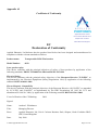
1
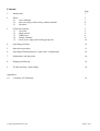
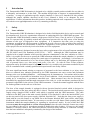
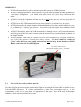
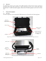
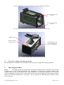
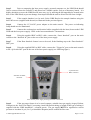
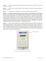
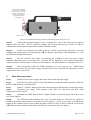
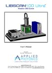
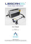
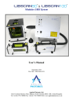
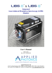
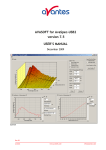
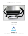
Transportable LIBS Workstation
Model No. 0158
User’s Manual
July 2008
Doc. Ref.: UM/0158/00
Applied Photonics Ltd
Unit 8 Carleton Business Park, Skipton, North Yorkshire BD23 2DE, United Kingdom
Tel +44 (0) 1756 708900 Fax +44 (0) 1756 708909 Web: www.appliedphotonics.co.uk
Contents
1.
Introduction
Page
3
2.
Safety
2.1
Laser radiation
2.2
Note on testing of laser safety window material
2.3
Electrical
3
3
4
5
3.
General description
3.1
Overview
3.2
Main console
3.3
LIBS Head
3.4
Sample chamber
3.5
Laser power supply and cooling group unit
5
5
6
6
8
10
4.
Operating procedure
10
5.
Shut-down procedure
13
6.
Operating LIBS instrument in “open beam” configuration
14
7.
Maintenance and inspection
14
8.
Shipping and Storage
14
9.
Trouble-shooting / fault finding
14
Appendices
A1
Certificate of Conformity
© 2008 Applied Photonics Ltd
16
Page 2 of 16
1
Introduction
The Transportable LIBS Workstation is designed to be a highly versatile product suitable for use either in
a laboratory environment or in the field. The modular design helps to improve its transportability and
versatility. A range of application-specific sample chambers is soon to be launched for this product,
although the sample chamber described in this User’s Manual is likely to be adequate for most
applications. Further information about this product, including optional extra components, is available at
our website www.appliedphotonics.co.uk or by contacting us directly.
2
Safety
2.1
Laser radiation
The Transportable LIBS Workstation is designed to be both a field-deployable device and a research and
development tool for use by organisations interested in conducting their own LIBS R&D program. The
Transportable LIBS Workstation contains a high-power Nd:YAG laser (Class 4) and so it is imperative
that it is operated only by suitably trained and experienced persons who are fully aware of the hazards
inherent to this type of high-power laser equipment. It is imperative also that, prior to using the
equipment, an appropriate risk assessment is conducted in such a way as to take account of the proposed
use of the equipment, the environment in which the equipment is to be operated, and how its use may
affect people who are not directly involved with the use of the equipment.
The LIBS instrument is designed to meet the laser safety requirements of the relevant European standards
(BS EN 60825) and USA standards (ANSI Z136.1 – 2007). Although the LIBS instrument may be
supplied with a sample chamber which provides adequate containment of the laser radiation to Class 1
limits, it is possible for the user to operate the LIBS instrument without the sample chamber (ie. operation
in “open beam” mode as may be required for certain types of experiment). Accordingly, it is necessary to
consider the LIBS instrument to be a Class 4 laser product and so, by definition, the equipment poses a
risk of personal injury (eye, skin injury) and poses a fire risk. As with all Class 4 laser products,
appropriate safety precautions must be taken as identified via a suitable risk assessment conducted by the
user in consultation with a suitably qualified and experienced Laser Safety Officer.
The most significant hazard relating to exposure of personnel to the laser radiation is eye injury since
direct or scattered laser radiation produced by the LIBS instrument can cause serious and permanent
damage to the eyes including blindness - such damage may be instantaneous. Precautions must be taken
to avoid exposure of personnel to hazardous levels of laser radiation. Such precautions may include the
setting up of a temporary or permanent controlled area. Other measures may also be necessary, as
determined by appropriate and thorough assessment of the risks (ie. a risk assessment) conducted by the
personnel responsible for the safe use of the LIBS instrument. Consult the manual supplied with the laser
for further guidance on the safe use of the laser.
The door of the sample chamber is equipped with an electrical interlock switch which is designed to
prevent activation of the laser unless the door is closed. The interlock switch connects to the laser power
supply using a length of BNC-to-BNC cable which is supplied with the LIBS instrument. The cable
connects to the BNC port on the main console (labelled “Laser Interlock”) and to the interlock BNC port
on the rear panel of the laser power supply (labelled “Interlock In”). Note that the laser power supply is
fitted with an over-ride feature (a cap which fits to the Remote Interlock BNC port) which, when fitted,
disables this safety interlock feature. It is necessary to use this over-ride feature when operating the LIBS
instrument without the sample chamber (ie. operating in “open beam” mode). In view of this, the LIBS
instrument must be categorised as a Class 4 laser product since the safety interlock feature may easily
be over-ridden by the user (ie. no tools are needed to disable this safety feature). If, however, the sample
chamber is correctly fitted to the LIBS Head and the electrical safety interlock is connected correctly,
then the laser radiation is adequately contained by the design of the hardware.
© 2008 Applied Photonics Ltd
Page 3 of 16
IMPORTANT
·
NEVER allow unauthorised and/or untrained personnel operate the LIBS instrument.
·
ALWAYS use appropriate laser safety protective eyewear when operating the LIBS instrument in
“open-beam” configuration – you should seek advice from your Laser Safety Officer on this
matter.
·
ALWAYS switch the instrument off when not in use and remove the key from the keyswitch of
the laser power supply to prevent unauthorised activation.
·
NEVER operate the LIBS instrument in areas where explosive gas mixtures may be present.
·
NEVER place inside the sample chamber flammable liquids or any other material which may give
rise to flammable / explosive gas mixtures. Activation of the laser under these conditions could
result in an explosion leading to severe personal injury and/or fire hazard.
·
ALWAYS thoroughly inspect the LIBS instrument for damage prior to use. Particular attention
should be given to the laser safety windows and the electrical safety interlock fitted to the door of
the sample chamber.
·
NEVER point the LIBS Head at a person (even with laser switched off), especially towards the
eyes, even if the person is wearing laser safety eyewear. The laser should be considered
“active” unless the laser power supply is deactivated and the safety shutter fitted to the LIBS
Head is switched to the CLOSED position.
Laser safety shutter switch
(Horizontal = OPEN, Vertical = CLOSED)
Image of LIBS Head showing location of laser safety shutter switch
2.2
Note on the laser safety window material
The laser safety window material fitted to the sample chamber is rated at OD 6+ @ 1064 nm. It therefore
provides adequate protection against scattered laser light of wavelength 1064 nm and so is suitable for use
with the LIBS instrument. It provides no protection at other laser wavelengths and so it is the
responsibility of the user to ensure that it is appropriate for the type of laser being used if the sample
chamber is used with an alternative laser source.
© 2008 Applied Photonics Ltd
Page 4 of 16
2.3
Electrical
The LIBS Head and laser power supply of the LIBS instrument contain electrical circuits operating at
potentially lethal voltage and current levels. Before removing any access covers, isolate mains power
from the laser. Consult the manual supplied with the laser for further guidance on the safe use of the
laser.
3
General description
3.1
Overview
The main components of the Transportable LIBS Instrument are illustrated in the following figures.
Pelicase™
container housing
main console
Main console
Modular sample
chamber
Flexible umbilical (~3
metres) connecting
LIBS Head to main
console
LIBS Head
Image showing main components of Transportable LIBS Workstation (laser power supply not shown)
Main console
Alternative
aperture cover
(opaque)
Flexible
umbilical
Removable
aperture cover
(transparent)
LIBS Head
Image showing main console and LIBS Head removed from Pelicase™
© 2008 Applied Photonics Ltd
Page 5 of 16
3.2
Main console
The main console, shown in the close-up view below, is semi-permanently fitted to the Pelicase™ as
illustrated above. The console provides the interface between the LIBS Head and i) the laser power
supply and ii) the personal computer, and contains the optical spectrometers (up to six spectrometer
modules may be installed). The console requires a 12 Volt DC electrical supply which is derived from
the mains electrical supply using the low-voltage adaptor (12 VDC, 5 Amps) supplied with the LIBS
instrument.
Inert gas inlet port
(requires 4 mm OD
plastic tubing) for
gas-purge of sample
Electrical connection for
laboratory door interlock
Laser interlock
(connects to laser
power supply)
Spectrometer trigger
input (connects to
laser power supply)
Over-ride cap for
Door Interlock
BNC port
Indicator lamp for 12
Volt DC power
12 Volt DC
power input
USB 2.0
connection for
external computer
Electrical fuses (1 Amp
for LIBS Head, 4 Amp
for spectrometers)
Close-up view of control panel of main console
3.3
LIBS Head
The LIBS Head contains the laser and associated optics required to focus the laser beam on to a sample
and collect the plasma light for transmission to the spectrometers located within the main console. The
main features of the LIBS Head are illustrated in the following figures. Use of the transparent aperture
cover allows the operator to view the laser plasma even when a sample is placed up against the aperture
cover. WARNING: Note that the transparent aperture cover provides no protection to the user
against exposure to the laser radiation.
LIBS Head fitted with opaque aperture cover
© 2008 Applied Photonics Ltd
LIBS Head fitted with transparent aperture cover
Page 6 of 16
LIBS Head with transparent aperture cover
LIBS Head with aperture cover removed
Electrical connection
to sample chamber
Circular array of six lens
holders – used to collect
plasma light
Laser beam aperture
Front view of LIBS Head showing plasma light lens holder array
Threaded fitting for
lens holder
Gas purge
outlet
Grub screw for locking aperture
cover (do not over-tighten)
Lens holder
© 2008 Applied Photonics Ltd
Page 7 of 16
Front view of LIBS Head showing three of the six lens holders removed
Water connections
Electrical connections
Rear view of LIBS Head showing electrical and water connections to laser
3.4
Sample Chamber
A general view of the sample chamber is given in the following figure. The sample chamber is designed
to fit to the LIBS Head using three M5 screws as illustrated in the figure on the following page. The
sample chamber is equipped with a small breadboard plate which is attached to a single-axis translation
stage. Transverse movement of the breadboard is achieved by manual adjustment of the knob on the side
of the sample chamber (see following figure).
Laser safety window
(OD6+ @ 1064 nm)
Electricallyinterlocked
hinged lid
Adjustment knob for
single-axis
translation stage
View of modular sample chamber
The sample chamber is equipped with a number of features as illustrated in the following figures. It is not
necessary to have the aperture cover fitted to the LIBS Head although it is useful to help define the
position where the sample should be placed on the breadboard plate inside the sample chamber.
© 2008 Applied Photonics Ltd
Page 8 of 16
View of modular sample chamber prior to attachment to LIBS Head
View of modular sample chamber attached to LIBS Head
M5 x 45 Cap Hd screw
Qty: 2
M5 x 30 Cap Hd screw
Qty: 1
© 2008 Applied Photonics Ltd
Page 9 of 16
CAD image illustrating the method of attachment of sample chamber to LIBS Head
M5 x 45 Cap Hd screws
(Qty: 2)
M5 x 30 Cap Hd screw
(Qty: 1)
View of modular sample chamber showing location of LIBS Head attachment screws
Magnetic catch
Electrical interlock
switches (Qty: 2)
Breadboard plate with
array of M6 tapped
holes on 25 mm centres
View of modular sample chamber showing electrical interlock
3.5
Laser power supply and cooling group unit
See manufacturer’s instructions for description of the laser power supply and cooling group unit.
4
Operating procedure
Step 1
The LIBS instrument should first be checked for obvious signs of damage, loose fixings,
etc prior to use. If any of the components of the instrument are found to be of suspect condition, take
remedial action before assembling and using the instrument. Of particular importance are the safety
critical components such as the laser safety windows and electrical lid interlock of the sample chamber.
Seek advice from the manufacturer if necessary. Do not operate the LIBS instrument with any of the
covers removed.
© 2008 Applied Photonics Ltd
Page 10 of 16
Step 2
Prior to connecting the laser power supply, personal computer etc, the LIBS Head should
first be removed from the Pelicase™ and placed on a suitable surface such as a laboratory bench. It is
highly desirable to secure the LIBS Head in some way (eg. by utilizing the M6 tapped holes located in the
base of the LIBS Head) to prevent damage from impact should the unit be allowed to fall from a height.
Step 3
If the sample chamber is to be used, fit the LIBS Head to the sample chamber using the
three M5 screws (supplied with the unit) as illustrated in the previous figures.
Step 4
Connect the 12 Volt DC power adaptor to the main console. The power on indicating
lamp should now be illuminated.
Step 5
Connect the coolant pipes and electrical cables (supplied with the laser) between the LIBS
Head and the laser power supply. Refer to the laser manufacturer’s instructions.
Step 6
Using the supplied BNC-to-BNC cable, connect the “Laser Interlock” port on the main
console to the “Interlock In” port on the rear of the laser power supply.
Step 7
BNC port.
If the Door Interlock feature is not to be used, fit the blanking cap to the “Door Interlock”
Step 8
Using the supplied BNC-to-BNC cable, connect the “Trigger In” port on the main console
to the “Q-Switch Out” port on the rear of the laser power supply (see following figure).
“Q-Switch Out”
BNC connector
“Interlock In” BNC
connector
View of laser power supply showing electrical connections
Step 9
If the gas-purge feature is to be used, connect a suitable inert gas supply (Argon, Helium,
Nitrogen) to the “Inert Gas Supply” port using 4 mm OD flexible tubing (a length of this type of tubing is
supplied with the LIBS instrument – coloured green). The gas supply MUST be regulated to restrict
pressure to less than 10 psi (2 to 3 psi should be adequate) and to control the flow-rate.
© 2008 Applied Photonics Ltd
Page 11 of 16
Step 10
Follow instructions supplied with laser for correct procedure for adding coolant water to
the laser power supply.
Step 11
Open laser safety shutter (located on LHS side panel of LIBS Head) by turning handle to
horizontal position.
Step 12
Activate laser by switching on key switch (see instructions supplied with laser).
Step 13
With the laser switched on (coolant water flowing, but laser flashlamp not yet activated),
check for correct operation of the safety interlock by observing the “Interlock” light on the front panel of
the laser power supply controller (see following figure) and opening / closing the lid of the sample
chamber (with LIBS Head fitted). If the interlock is working correctly, the “Interlock” light should flash
when the sample chamber lid is open and be constantly illuminated when the lid is closed. If the interlock
is found not to be operating correctly, refer to the Fault Finding section of this User’s Manual. Note that
if the LIBS Head is removed from the sample chamber, the interlock circuit is designed to de-activate the
laser (see section 6 on Operating instrument in “open-beam” configuration). Warning – do not operate
the LIBS instrument if the safety interlock is not functioning correctly.
Step 14
Place a sample of material (eg. a metal block) at the focal plane of the Nd:YAG laser beam
inside the sample chamber. Using the controls on the front panel of the laser power supply controller (see
following figure and refer to laser manufacturer’s instructions), the laser beam may now be fired by i)
first activating the flashlamp and ii) then activating the Q-Switch. If the sample material is located at or
near to the focal plane of the laser beam, a laser-induced plasma will be produced on the surface of the
sample. It may be necessary to adjust the position of the aperture cover to obtain correct positioning of
sample surface (see figure on following page).
Fault warning light
View of front panel of laser power supply controller
© 2008 Applied Photonics Ltd
Page 12 of 16
Distance may be adjusted
by several mm by rotating
the aperture cover. Use this
feature to set position of
aperture cover to facilitate
correct positioning of
sample surface
Locking screw
CAD view of LIBS Head showing method for adjusting position of aperture cover
Step 15
Connect the personal computer to the “Computer I/O” port of the main console using the
supplied USB 2.0 cable. The PC should be running the AvaSoft spectroscopy software in order to
communicate with the optical spectrometers within the main console.
Step 16
Follow the instructions provided with the AvaSoft spectroscopy software to correctly
configure the spectrometers for acquiring data. NB As shipped, spectrometer with bandwidth 711 - 900
nm should be configured as master.
Step 17
Fire the Nd:YAG laser beam by activating the Q-Switch on the laser power supply
controller (flashlamp must be activated also). Spectra will be acquired by the AvaSoft spectroscopy
software and stored to the memory of the personal computer (if AvaSoft software is configured to do so).
Step 18
After successfully testing the LIBS instrument, it is now ready for use. Measurement
conditions such as Nd:YAG laser pulse energy and laser beam focus will need to be adjusted to suit the
requirements of the experiment.
5.
Step 1
Shut-down procedure
Switch off laser power supply and isolate from mains electrical supply.
Step 2
Close the laser safety shutter on the LIBS Head by turning the handle (located on LHS side
panel of LIBS Head) to vertical position.
Step 3
Isolate 12 Volt DC adaptor from mains electrical supply and disconnect from main console
Step 4
Disconnect gas supply, USB computer cable, laser I/O connections and BNC cable
connections to main console
Step 6
Dismantle the LIBS Head from the sample chamber by unscrewing the three M5 screws
(see earlier figures)
Step 8.
The LIBS Head and umbilical may now be stored inside the Pelicase™ by laying the
umbilical around the main console (as shown in previous figures). It may be necessary to compress the
length of the umbilical while laying around the main console in order to allow sufficient room for the
LIBS Head to locate at the front left side of the Pelicase (as shown in previous figures).
© 2008 Applied Photonics Ltd
Page 13 of 16
6.
Operating LIBS instrument in “open beam” configuration
The Transportable LIBS Workstation may be used without the sample chamber if required. Under these
conditions, the laser beam is not contained and hence additional safety precautions must be observed
including the use of appropriate laser goggles and operating the LIBS instrument in a suitable laser
laboratory environment. It is the responsibility of the user to conduct an appropriate risk assessment prior
to using the LIBS instrument in open-beam mode. If the sample chamber is not fitted to the LIBS Head,
it will be necessary to disconnect the BNC cable to the “Interlock In” port on the laser power supply and
fit the blanking cap so as to disable the safety interlock feature.
WARNING: As outlined in Section 2.1, fitting the blanking plug to the “Interlock In” port on the laser
power supply will disable the sample chamber safety interlock feature and allow the LIBS Head to emit
potentially hazardous levels of laser radiation (i.e. Class 4 laser system). It is the responsibility of the
user to ensure that safety is maintained when operating the Transportable LIBS Workstation in this mode
of operation. As a minimum, it will be necessary to operate the Transportable LIBS Workstation in a
laser controlled area (e.g. a laser laboratory) and for all personnel in the controlled area to wear
appropriate laser protective eyewear. Consult your Laser Safety Officer before operating the
Transportable LIBS Workstation in this mode.
7.
Maintenance and inspection
The Transportable LIBS Workstation should be periodically inspected for signs of damage or wear and
tear. Of particular importance are the safety features including the laser safety windows and the lid
interlock switch mechanism. If any damage to the laser windows of the sample chamber is observed or
suspected, the LIBS instrument should be temporarily removed from service until a replacement window
is fitted. For maintaining and inspecting the laser, the documentation supplied with the laser should be
consulted. If necessary, contact the manufacturer of the LIBS instrument for further advice on
maintenance and inspection of the product.
8.
Shipping and Storage
The laser power supply and laser head (within the LIBS Head) MUST be drained of coolant water if there
is any possibility of the unit being exposed to temperatures below 4 Celsius. Failure to do so could result
in serious damage to the laser head and/or the laser power supply. The laser manufacturer’s instructions
should be followed for draining coolant water from the laser power supply. For draining the coolant
water from the laser head, following the procedure given in the laser manufacturer’s instructions.
9.
Trouble-shooting / fault finding
Laser does not activate:
1. Is the laser shutter on the LIBS Head set to the OPEN position?
2. Is safety interlock connected correctly?
3. Is “Interlock” indicator light on laser power supply controller flashing? If yes, then check that
sample chamber door is fully closed. If sample chamber is not fitted to LIBS Head and instrument
is required to be operated in “open-beam” mode, then the blanking plug must be fitted to the
“Interlock In” BNC connector on the laser power supply.
4. If the safety interlock appears to be working correctly but the laser still does not activate, refer to
the operating instructions provided with the laser.
© 2008 Applied Photonics Ltd
Page 14 of 16
Laser-induced plasma appears to be adequately intense although a poor signal is observed on some
or all of the spectrometer channels:
1. Are the data acquisition settings on the AvaSoft software set up correctly?
2. Is the composition of the sample such that emission lines are not expected to be seen on some or
all of the spectrometer channels? If yes, then use an alternative sample which has numerous
emission lines (eg. iron-containing material) to check for correct operation of the LIBS
instrument.
3. Is the sample positioned correctly relative to the laser beam focus? It may be necessary to adjust
the position of the aperture cover.
4. Is the laser pulse energy too low? Increase if necessary
Recorded spectra show some emission lines which are saturating the detector (“flat top”
appearance to the emission line):
1. Reduce the pulse energy of the laser using the controls on the front panel of the laser power
supply
2. Increase spot size of laser beam on sample by adjusting the position of the sample relative to the
focal plane of the laser beam.
Recorded spectra show some emission lines suffering from “self-reversal” (ie. a “dip” in the centre
of the emission line):
1. Reduce the pulse energy of the laser using the controls on the control panel of the laser power
supply
2. Increase spot size of laser beam on sample by adjusting the position of the sample surface relative
to the focal plane of the laser beam (it is usual to set focus to be a few millimetres “into” the
sample surface)
Air-breakdown is observed in the path of the laser beam just in front of the sample surface:
1. The focal plane of the laser beam is set incorrectly (ie. it is set to be in front of the sample) –
adjust position of sample so that the focal plane of the laser beam is coincident, or preferably just
“into”, the sample surface.
2. On irradiation by the laser beam, the sample is creating considerable quantities of dust in the path
of the laser beam. Try cleaning surface of the sample if loose material (eg oxide, surface
contamination etc) is present.
© 2008 Applied Photonics Ltd
Page 15 of 16
Appendix A1
Certificate of Conformity
Applied Photonics Limited
Unit 8 Carleton Business Park
Skipton North Yorkshire
BD23 2DE United Kingdom
EC
Declaration of Conformity
Applied Photonics Ltd declares that the product listed below has been designed and manufactured in
compliance with the relevant standards as follows:
Product name:
Transportable LIBS Workstation
Model Number:
0158
Laser product safety
This device conforms with the principal objectives of safety of laser products by application of the
following standards: PD IEC TR 60825-14:2004 and BS EN 207:1999
Electrical Safety
This device conforms with the principal safety objectives of the European Directive 73/23/EEC, as
implemented by the Electrical Equipment (Safety) Regulations 1994, by application of the following
standard: BS EN 61010-1:2001.
Electro-Magnetic Compatibility
This device conforms with the principal objectives of the European Directive (89/336/EEC) as amended
by 91/31/EEC and 93/68/EEC, as implemented by The EMC Regulations (SI 1992 No. 2372 and
amendment SI 1994 No. 3080), by application of the following standard: BS EN 61326-1:2006
Year of affixation of the CE Marking:
2008
Signed:
Name:
Andrew I. Whitehouse
Title:
Managing Director
Place:
Applied Photonics Ltd, Unit 8 Carleton Business Park, Skipton, North Yorkshire BD23
2DE, United Kingdom
Date:
July 2008
© 2008 Applied Photonics Ltd
Page 16 of 16