1
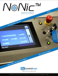
Integrated
Laser-Induced Breakdown Spectroscopy (LIBS)
Modules
User’s Manual
March 2015
Doc. Ref.: UM/2020/01
Applied Photonics Ltd
Unit 8 Carleton Business Park, Skipton, North Yorkshire BD23 2DE, United Kingdom
Tel +44 (0) 1756 708900 Fax +44 (0) 1756 708909 Web: www.appliedphotonics.co.uk
Contents
1.
Introduction
Page
3
2.
Safety
2.1
Laser radiation
2.2
Note on the laser safety window material used in the modular sample chambers
2.3
Electrical
3
3
6
6
3.
General description
3.1
Overview
3.2
Laser beam expander and plasma light collection optics
3.3
Attaching the LIBS module to a laser
3.4
Modular sample chambers
3.4.1 SC-2C modular sample chamber
3.4.2 SC-2L modular sample chamber
3.5
Quantel Ultra ICE 450 laser power supply and Interlock Override Keyswitch
3.6
Imaging camera and associated components
3.7
Low-voltage electrical connections
3.8
Assembly of system based on LIBS-8, Ultra laser and SC-2L sample chamber
7
7
9
10
12
13
15
19
21
22
22
4.
Operating procedure
4.1
Introduction
4.2
Important note on back-reflections of laser radiation
4.3
Step-by-Step guide to operating the LIBS equipment
24
24
24
25
5.
Shut-down procedure
28
6.
Operating LIBS-6 and LIBS-8 modules in “open beam” configuration
28
7.
Maintenance and inspection
29
8.
Shipping and storage
29
9.
Trouble-shooting / fault finding
30
Appendices
A1
Certificate of Conformity
© 1998 - 2015 Applied Photonics Ltd
31
Page 2 of 31
1
Introduction
The LIBS-6 and LIBS-8 integrated Laser-Induced Breakdown Spectroscopy (LIBS) modules are designed
to be a highly versatile product for use by research scientists, application engineers and OEMs.
Essentially a “LIBS system building block”, the LIBS-6 and LIBS-8 modules may be used together with a
variety of Q-switched Nd:YAG lasers and optical spectrometers to form a customised, modular LIBS
system tailored to suit the requirements of a specific application or experimental research project. The
LIBS modules remove the need for the research scientist or application engineer to design and construct
their own laser focussing optics and plasma light collection optics by combining these features into a
compact, integrated and easy to use device. An optional imaging kit may be added to the LIBS module,
increasing further its functionality and versatility.
This User’s Manual provides the necessary information needed to configure the integrated LIBS modules
and how to use them safely. It is assumed that the user will be familiar with the safety issues arising from
the use of high-power lasers and will have preferably been trained in the safe use of high-power (Class 4)
laser products.
2
Safety
2.1
Laser radiation
The LIBS-6 and LIBS-8 integrated LIBS modules are designed for use with a high-power Q-switched
Nd:YAG laser (Class 4) and so it is imperative the equipment is operated only by suitably trained and
experienced persons who are fully aware of the hazards inherent to this type of high-power laser
equipment. It is imperative also that, prior to using the equipment, an appropriate risk assessment is
conducted in such a way as to take account of the proposed use of the equipment, the environment in
which the equipment is to be operated, and how its use may affect people who are not directly involved
with the use of the equipment.
Example of a laser warning product label
The LIBS-6 and LIBS-8 integrated LIBS modules are designed to meet the laser safety requirements of
the relevant European standards (BS EN 60825) and USA standards (ANSI Z136.1 – 2007). Although
these products may be supplied with a sample chamber which provides adequate containment of the laser
radiation to Class 1 Accessible Emission Limits, it is possible for the user to operate the LIBS modules
without the sample chamber (ie. operation in “open beam” mode as may be required for certain types of
experiment). Accordingly when fitted to an appropriate laser, it is necessary to consider the LIBS
modules to be Class 4 Laser Products and so, by definition, the equipment poses a risk of personal
injury (eye, skin injury) and poses a fire risk. As with all Class 4 laser products, appropriate safety
precautions must be taken as identified via a suitable risk assessment conducted by the user in
consultation with a suitably qualified and experienced Laser Safety Officer.
© 1998 - 2015 Applied Photonics Ltd
Page 3 of 31
The most significant hazard relating to exposure of personnel to the laser radiation is eye injury since
direct or scattered laser radiation produced by the equipment can cause serious and permanent injury to
the eyes including blindness - such injury may be instantaneous. Precautions must be taken to avoid
exposure of personnel to hazardous levels of laser radiation. Such precautions may include the setting up
of a temporary or permanent laser controlled area (eg. a laser laboratory). Other measures may also be
necessary, as determined by appropriate and thorough assessment of the risks (ie. a risk assessment)
conducted by the personnel responsible for the safe use of the laser equipment. Consult the manual
supplied with the laser for further guidance on the safe use of the laser.
The door of the sample chamber is equipped with a dual electrical interlock switch which is designed to
prevent activation of the laser unless the door is fully closed. The door interlock switch is electrically
connected to the “Interlock In/Out” port on the LIBS module via the 9-pin connector located directly
above the laser aperture. The “Interlock In/Out” port connects with the SpectroModule-6 (using the
supplied lead) which in turn is connected to the interlock circuits of the laser power supply. The laser
safety interface between the SpectroModule-6 and the laser power supply depends on the make and model
of laser being used. Throughout this User’s Manual, it is assumed that a Quantel Ultra laser with ICE 450
power supply is being used.
Removal of the sample chamber from the LIBS module, or disconnection of the Interlock In/Out lead,
will also activate the interlock (ie. prevent activation of the laser). The SpectroModule-6 is equipped with
an Interlock Override facility (a keyswitch) which allows the interlock to be disabled so that the LIBS
system may be used without a sample chamber (ie. “open beam” mode). In view of this, the LIBS
modules must be categorised as a Class 4 laser product since, by design, the product may be used in
such a way that the laser beam is not contained (ie. “open beam” mode of operation) . If, however, the
sample chamber is correctly fitted to the LIBS module and the Interlock Override keyswitch is switched
off and the key removed, then the laser radiation is adequately contained to Class 1 Accessible Emission
Limits by the design of the hardware.
IMPORTANT
•
READ and UNDERSTAND both this User’s Manual and the instructions provided by the
manufacturer of the laser before operating the integrated LIBS module (LIBS-6 or LIBS-8) and
associated laser equipment.
•
ENSURE that an appropriate risk assessment has been conducted to establish whether or not the
laser safety windows fitted to the modular sample chambers provide adequate protection against
exposure to laser radiation for the specific laser you intend to use with the LIBS equipment .
For advice on this matter, consult your Laser Safety Officer and/or Applied Photonics Ltd.
•
ONLY suitably qualified and authorised persons should activate the Interlock Override keyswitch.
The key should be removed from the keyswitch and held by the Laser Safety Officer when this
feature is not required.
•
ALWAYS use appropriate laser safety protective eyewear when operating the LIBS modules and
associated laser equipment in “open-beam” configuration – you should seek advice from your
Laser Safety Officer on this matter.
•
ALWAYS switch the laser off when not in use and remove the key from the keyswitch of the laser
power supply to prevent unauthorised activation.
© 1998 - 2015 Applied Photonics Ltd
Page 4 of 31
•
ALWAYS thoroughly inspect the LIBS module and associated laser equipment for damage prior
to use. Particular attention should be given to the laser safety windows and the laser safety
interlock system, which should be tested each time the equipment is used.
•
NEVER allow unauthorised and/or untrained persons operate the LIBS module and associated
laser equipment.
•
NEVER operate the LIBS module and associated laser equipment in areas where explosive gas
mixtures may be present.
•
NEVER operate the LIBS module and associated laser equipment with any access cover, panel, or
protective window removed.
•
NEVER place inside the sample chamber flammable liquids or any other material which may give
rise to flammable / explosive gas mixtures. Activation of the laser under these conditions could
result in an explosion leading to severe personal injury and/or fire hazard. Remember that the
laser-induced plasma is a source of ignition.
•
NEVER point the LIBS module and associated laser equipment at a person (even with laser
switched off), especially towards the eyes, even if the person is wearing laser safety eyewear. The
laser should be considered “active” unless the laser power supply is deactivated and the
safety shutter fitted to the laser head is switched to the CLOSED position .
•
NOTE that neither the opaque black Delrin nozzle aperture nor the transparent acrylic nozzle
aperture provide any protection to the user against exposure to direct or scattered laser radiation.
The function of the nozzle aperture is described later in this User’s Manual.
Laser warning
indicator light
Laser aperture
warning label
Laser aperture
Image of LIBS-6 module showing location of laser warning indicator light, laser aperture and warning label
© 1998 - 2015 Applied Photonics Ltd
Page 5 of 31
2.2
Note on the laser safety window material used in the modular sample chambers
The laser safety window material fitted to the sample chamber is rated as follows:
Laser
Wavelength
(nm)
1064
355
266
USA Standard
ANSI Z 136.1 – 2000
UK & European Standard
BS EN 207:1999
Optical
Density
OD 6
OD 5
OD 3
Protection Level R
(Q-switched laser)
L6
L5
L3
R L6 at 1064 nm indicates a protection level of maximum spectral transmittance of 10 -6 at 1064 nm for a
pulsed laser of pulse length 10 -9 – 10-7 seconds (ie. a Q-switched laser).
The laser safety windows used in Applied Photonics Ltd’s range of modular sample chambers provide
adequate protection against scattered laser light of wavelength 1064 nm, 355 nm and 266 nm such that
Class 1 Accessible Emission Limits are met if the sample chamber is used correctly and laser pulse
energies are not excessively high (ie. typically less than 250 mJ with a 5 - 10 ns pulse length). Note that
the protective windows are NOT suitable for use with a 532 nm laser. Given that the LIBS-6 and LIBS-8
modules may be used with a variety of lasers, it is the responsibility of the user to conduct a risk
assessment to establish whether or not the laser safety windows provide adequate protection for the
particular laser being used. If in any doubt, you should consult your Laser Safety Officer and/or Applied
Photonics Ltd for advice on this matter.
Warning – the Applied Photonics Ltd modular sample chambers are designed specifically for use
with our LIBS-6 / LIBS-8 integrated LIBS modules and our LIBSCAN range of products and
should not be used with any other laser device or product. If in doubt, seek advice from the
manufacturer, Applied Photonics Ltd.
2.3
Electrical
The LIBS-6 and LIBS-8 integrated LIBS modules contain electrical circuits operating at 12 VDC at a
maximum current of 2.5 Amps. Accordingly, they pose no electric shock risk. The laser head and
associated power supply, however, contain electrical circuits operating at potentially lethal voltage and
current levels. Consult the manufacturer’s User Manual supplied with the laser for further guidance on
the safe use of the laser.
© 1998 - 2015 Applied Photonics Ltd
Page 6 of 31
3
General description
3.1
Overview
The main components of the LIBS-6 integrated LIBS module are illustrated in the following figures. The
LIBS-8 module is essentially identical to the LIBS-6 module except that it has eight plasma light
collection channels rather than six.
© 1998 - 2015 Applied Photonics Ltd
Page 7 of 31
HighLaser intensity LED
warning
dimmer
light
control
Laser
interlock
connection
Electrical connection
(to sample chamber)
Electronics enclosure
Lock
screw
Transparent
nozzle
aperture
Front
bulkhead
Camera
housing
Optics
array
Beam
expander
Cut-away to allow
adjustment of laser focus
Laser beam tube
Fibre-optic
cable
Threaded
ring
HighPlasma light intensity
collection
LEDs
lens holder
Gas-purge
port
Tie-bar
Rear
bulkhead
The LIBS modules provide the following features:
•
Plasma light collection lens array having a relatively large depth-of-field to allow efficient light collection even when
plasma position varies by ±5 mm along optic axis of laser beam.
•
3-lens laser beam expander with adjustable focus (adjustment of focal plane made by rotating the brass beam
expander lens holder via the cut-way in the laser beam tube – adjustment range of approx. 15 mm).
Adjustable nozzle aperture which provides a convenient means of setting the distance to the sample surface
(adjustment range of approx. 15 mm). The nozzle aperture may be removed if this feature is not required.
Gas-purge port (accepts 4 mm flexible nylon tube) which may be used to feed inert gas (eg. argon, helium, nitrogen)
to the sample surface. To ensure purge gas is directed to the sample, it is necessary to fit the nozzle aperture.
•
•
•
Optional miniature CCD colour video camera with array of dimmable high-brightness white LEDs for illuminating
sample surface.
•
•
Laser safety interlock with keyswitch operated override facility (via the SpectroModule-6 spectrometer).
Compatible with the Applied Photonics Ltd range of modular sample chambers.
© 1998 - 2015 Applied Photonics Ltd
Page 8 of 31
Laser warning
indicator light
Electrical connection
to sample chamber
Miniature CCD
camera
(optional feature)
Grub screw for locking
aperture nozzle (do not
over-tighten)
Circular array of highbrightness white LED lights
(optional feature)
Circular array of six lens
holders – used to collect
plasma light. The blue lens
holders are for collection of
UV-VIS while the red lens
holders are for collection of
VIS-NIR. LIBS-8 version has
4 UV-VIS (blue) and 4 VISNIR (red) lens holders.
Gas purge outlet
Laser beam expander
and output aperture
Front view of LIBS-6 module showing plasma light collection lens array,
CCD camera, LED lights, laser aperture and gas purge outlet
The above diagrams illustrate the LIBS-6 module. Throughout the remainder of this User’s Manual, for
the purposes of simplicity, only the LIBS-6 module together with a Quantel Big Sky Ultra laser and either
the SC-2C or the larger SC-2L modular sample chambers are described.
3.2
Laser beam expander and plasma light collection optics
The optical configuration used in the integrated LIBS modules is illustrated schematically in the
following diagram. The laser beam expander consists of three lenses and is used to provide a tightly
focussed laser beam at nominally 90 mm from the aperture of the beam expander (80 mm for the LIBS-6
beam expander). The optical design is specific to the make and model of laser which the LIBS module is
to be used with – this is specified at the time of ordering of the LIBS module. The brass tubular piece
which houses the beam expander lenses is threaded so that rotating it causes the focal plane of the laser
beam to move. The design allows for approximately ±7.5 mm of adjustment, as illustrated in the
following diagrams. The plasma light collection optics are angled at approx. 15.7 degrees (17.4 degrees
for the LIBS-6 module) and are designed to collect light from the region in space defined in the following
diagram. The transparent aperture nozzle is threaded so that rotation causes it to move along the optic
axis of the laser beam – range of travel is approximately ±7.5 mm (it may be removed from the body of
the LIBS module by unscrewing further). The main purpose of the transparent aperture nozzle is to
provide a convenient means of setting the distance to the sample surface. The nozzle aperture also
provides containment of the purge gas to ensure the sample surface and laser-induced plasma region are
effectively purged of atmospheric air, and provides physical protection for the laser and plasma light
collection optics (and imaging camera if fitted).
© 1998 - 2015 Applied Photonics Ltd
Page 9 of 31
Transparent
aperture nozzle
Fibre-optic cable
to spectrometer
Adjustment range of
transparent aperture nozzle
(approx. ±7.5 mm)
Brass holder
containing laser beam
expander lenses
Laser Beam
Laser Beam
Threaded section
Fibre-optic cable
to spectrometer
Threaded section
Adjustment range of focal
plane of laser beam
(approx. ±7.5 mm)
±7.5 mm
±7.5 mm
Close-up view of laser beam focus and fieldof-view of plasma light collection optics
3.3
Attaching the LIBS module to a laser
The LIBS modules are suitable for use with virtually any commercially-available Q-switched Nd:YAG
laser which has operating characteristics appropriate for LIBS. In order to attach either the LIBS-6 or
LIBS-8 module to a laser head, it is necessary to use an appropriate adaptor platform. At the time of
writing of this User’s Manual, Applied Photonics Ltd supplies adaptor platforms for the following lasers:
Laser Product
Quantel Brilliant and Brilliant B
Quantel (Big Sky) Ultra CFR range of lasers
Quantel (Big Sky) CFR 200 range of lasers
Quantel (Big Sky) CFR 400 range of lasers
Adaptor Platform
AP-Brilliant
AP-Ultra
AP-CFR200
AP-CFR400
Should your laser not be listed above, contact Applied Photonics Ltd giving details of the make and
model of your laser to enquire about availability of a suitable adaptor platform.
© 1998 - 2015 Applied Photonics Ltd
Page 10 of 31
The method of assembly of the adaptor platform and laser head is illustrated in the following figures.
Quantel Big Sky Ultra
CFR laser head
Laser safety
shutter
AP-Ultra
adaptor platform
M4 x 12
Hex Cap Hd Screws
Qty 4
No 6 UNC x ¾”
Hex C/S Hd Screws
Qty 3
LIBS-6 module fitted to Quantel Big Sky Ultra laser head using AP-Ultra adaptor platform
© 1998 - 2015 Applied Photonics Ltd
Page 11 of 31
3.4
Modular sample chambers
A range of modular sample chambers is available for use with the LIBS-6 / LIBS-8 modules (see table
below). These sample chambers are also suitable for use with our LIBSCAN range of products. Two
types (SC-2C and SC-2L) are described in more detail in the remainder of this User’s Manual.
SC-1
SC-2C
SC-2M
SC-2L
Single axis translation stage, 20
mm travel per stage (manual
control).
2-axis translation stage, 20 mm
travel per stage (manual control).
2-axis translation stage, 20 mm
travel per stage (manual control)
Fume extract port. Internal LED
light.
Approx. overall dimensions: 160
x 160 x 260 mm, approx. 4.0 kg
3-axis translation stage, 50 mm
travel per stage (manual control).
Fume extract port. Internal LED
light.
Approx. overall dimensions: 280 x
250 x 330 mm, 15 kg
Approx. overall dimensions: 110 x
120 x 210 mm, approx. 2.0 kg
Approx. overall dimensions: 110 x
120 x 260 mm, approx. 2.5 kg
SC-2XL
3-axis translation stage, 50 mm
travel per stage (manual control).
Fume extract port. Internal LED
light.
Approx. overall dimensions: 330 x
360 x 430 mm, approx. 20 kg
XYZ-750
XYZ-2500
3-axis translation stage, 75 mm
travel per stage (computercontrolled). Fume extract port.
Internal LED light.
Approx. overall dimensions: 330 x
360 x 480 mm, approx. 24 kg
3-axis translation stage, X & Y
travel = 250 mm, Z travel = 100
mm. Fume extract port. Internal
LED light.
Approx. overall dimensions: 470 x
770 x 730 mm, approx. 56 kg
SC-LQ1
Modular sample chamber
designed to analyse liquids.
Liquid drain port in base of
chamber. Note: This sample
chamber is currently being
redesigned
Current range of modular sample chambers manufactured by Applied Photonics Ltd
WARNING
The above range of modular sample chambers are designed specifically for use with the LIBS-6 / LIBS-8
integrated LIBS modules or the LIBSCAN range of modular LIBS systems. The specifications for the
laser safety windows are as follows:
Laser
Wavelength
(nm)
1064
355
266
USA Standard
ANSI Z 136.1 – 2000
UK & European Standard
BS EN 207:1999
Optical
Density
OD 6
OD 5
OD 3
Protection Level R
(Q-switched laser)
L6
L5
L3
R L6 at 1064 nm indicates a protection level of maximum spectral transmittance of 10 -6 at 1064 nm for a
pulsed laser of pulse length 10 -9 – 10-7 seconds (ie. a Q-switched laser).
Since the LIBS-6 / LIBS-8 integrated LIBS modules may be used with various laser devices, it is the
responsibility of the user to establish whether the protection offered by the laser safety windows is
adequate for the laser being used. If in doubt, seek advice from a suitably qualified Laser Safety Officer
or contact Applied Photonics Ltd before operating the laser equipment.
© 1998 - 2015 Applied Photonics Ltd
Page 12 of 31
3.4.1 SC-2C modular sample chamber
A general view of the SC-2C modular sample chamber is given in the following figure. The sample
chamber is equipped with a breadboard plate which is attached to a manual two-axis translation stage
(approx. 20 mm travel per stage). The breadboard plate has an array of M6 tapped (blind) holes on 25
mm centres and which may be used to facilitate the attachment of a sample holder etc. Movement of the
breadboard is achieved by adjustment of the knobs on the side and top of the sample chamber, as
illustrated below.
Adjustment knob
for y-axis
translation stage
Laser safety window
Door with
magnetic catch
and dual electrical
interlocks
Adjustment knob for
x-axis translation
stage
View of SC-2C modular sample chamber
The sample chamber is equipped with a number of features as illustrated in the following figures.
Electrical connection
to LIBS module
Door with
magnetic catch
and dual electrical
interlocks
CAD view of SC-2C modular sample chamber
© 1998 - 2015 Applied Photonics Ltd
Page 13 of 31
Adjustment knob
for y-axis
translation stage
Door with
magnetic catch
and dual electrical
interlocks
Attachment screws
for fitting sample
chamber to LIBS
module
Adjustment knob for
x-axis translation
stage
Breadboard plate (with
array of M6 tapped holes
on 25 mm centres)
CAD view of SC-2C modular sample chamber
The SC-2C modular sample chamber is designed to fit to the LIBS module using four M5 screws as
illustrated in the following figures. Before fitting the sample chamber to the LIBS module, ensure that
the breadboard plate is positioned sufficiently low so as not to make contact with the aperture nozzle of
the LIBS module (use the y-axis adjustment knob to lower the breadboard plate). Be careful to fit the
sample chamber squarely to the LIBS module so as not to cause damage to the electrical connectors.
Secure SC-2C sample chamber to
the LIBS-6 module using the four
M5 cap head screws
CAD views of SC-2C modular sample chamber illustrating method of attachment to LIBS-6 module
© 1998 - 2015 Applied Photonics Ltd
Page 14 of 31
CAD views of SC-2C modular sample chamber attached to LIBS-6 module
3.4.2 SC-2L modular sample chamber
A general view of the SC-2L modular sample chamber is given in the following figure. The sample
chamber is equipped with a breadboard plate which is attached to a manual three-axis translation stage
(50 mm travel per stage). The breadboard plate has an array of M6 tapped (blind) holes on 25 mm centres
and which may be used to facilitate the attachment of a sample holder etc. Movement of the breadboard
is achieved by adjustment of the knobs on the sides and top of the sample chamber, as illustrated below.
Adjustment knob
for z-axis
translation stage
Laser safety
windows
Door with
magnetic catch
and dual electrical
interlocks
Adjustment knob
for x-axis translation
stage
Adjustment knob
for y-axis
translation stage
View of SC-2L modular sample chamber
© 1998 - 2015 Applied Photonics Ltd
Page 15 of 31
The sample chamber is equipped with a number of features as illustrated in the following figures.
CAD views of SC-2L modular sample chamber
Fume extract
nozzle
Z-axis
adjustment knob
Gooseneck
LED light
Breadboard plate (with
array of M6 tapped holes
on 25 mm centres)
Electrical door
interlock switch
Magnetic catch
for door
Electrical door
interlock switch
X-axis
adjustment knob
Feet suitable for
attachment to a metric or
imperial optical table
Y-axis
adjustment knob
CAD view of SC-2L modular sample chamber
© 1998 - 2015 Applied Photonics Ltd
Page 16 of 31
Fume extraction port – for
optional connection to an
external air extraction unit
(1/2” BSPP thread)
Label for laser
safety windows
CAD view of rear panel of SC-2L modular sample chamber
The LIBS-8 and LIBS-6 modules are designed to fit to the top of the sample chamber using four M5
screws as illustrated in the following figures. Before fitting the LIBS module to the sample chamber,
ensure that the breadboard plate is positioned sufficiently low so as not to make contact with the aperture
nozzle of the LIBS module. Be careful to fit the LIBS module squarely to the sample chamber so as not
to cause damage to the electrical connectors.
Secure LIBS-6 module to
SC-2L sample chamber
using the four M5 cap
head screws
Secure LIBS-6 module to
SC-2L sample chamber
using the four M5 cap
head screws
CAD view of SC-2L modular sample chamber illustrating method of attachment of LIBS-6 module
© 1998 - 2015 Applied Photonics Ltd
Page 17 of 31
Ultra laser
head
head
AP-Ultra
adaptor plate
LIBS-6
module
SC-2L modular
sample chamber
Breadboard
sample table
CAD view of LIBS-6 module with Ultra laser fitted to SC-2L modular sample chamber
© 1998 - 2015 Applied Photonics Ltd
Page 18 of 31
Gooseneck
LED light
Fume extract
nozzle
Laser
plasma
Breadboard sample
table (with array of
M6 tapped holes on
25 mm centres)
Sample
Close-up view of inside of SC-2L sample chamber with LIBS-6 module fitted
and showing a laser-induced plasma on a metallic sample
3.5
Quantel Ultra ICE 450 laser power supply and Interlock Override Keyswitch
See the Quantel’s instructions for a complete description of the ICE 450 laser power supply and cooling
group unit. The electrical connections between the ICE 450 power supply and the SpectroModule-6 are
illustrated schematically in the following diagram.
WARNING It is necessary to fit the BNC clamping piece (after connecting the interlock BNC
connectors) in order for the LIBS system to meet Class 1 Laser Product standards.
Interlock OUT
BNC port
Interlock IN
BNC port
Q-Switch
OUT
BNC port
BNC clamping piece
(used to prevent unauthorised disconnection of
laser safety interlock BNC connectors)
RS232 serial port
(labelled 1O1O1)
Schematic diagram illustrating interlock, Q-Switch OUT and RS232 electrical connections to ICE 450 laser power supply
© 1998 - 2015 Applied Photonics Ltd
Page 19 of 31
The Interlock Override keyswitch located on the control panel of the SpectroModule-6 is used to override
the laser safety interlock when the LIBS-6 or LIBS-8 module is required to be used in “open beam”
configuration (ie. without a sample chamber). To override the interlock, the keyswitch should be turned
“on” by turning clock-wise as indicated in the image below. The orange / yellow LED indicator to the
left of the keywitch (labelled Class 4 Warning) will flash continuously when the keyswitch is activated
and the laser is in “active” mode. When the keyswitch is set to “off”, the LED will be extinguished
indicating that the laser safety interlock is operating. The key should be removed from the Interlock
Override keyswitch to prevent unauthorised activation of the interlock override.
WARNING When the Interlock Override keyswitch is activated, the LIBS system becomes a Class 4
Laser Product, hence appropriate safety procedures and precautions MUST be adopted when operating
the LIBS system in this mode.
Laser Interlock
Override Keyswitch
and warning
indicator LED
Image illustrating Interlock Override keyswitch on the SpectroModule-6 control panel
© 1998 - 2015 Applied Photonics Ltd
Page 20 of 31
3.6
Imaging camera and associated components
The imaging camera is offered as an optional feature for both the LIBS-6 and the LIBS-8 modules
(product code IMG-1). As illustrated below, a miniature colour CCD camera is located within the green
tubular holder at the 12 o’clock position adjacent to the array of plasma light collection optics. The
tubular holder is fitted with an optical filter to protect the CCD camera from damage due to possible high
levels of stray laser light (laser wavelength must be specified when placing an order). The camera
requires a 12 VDC supply which is derived from the power in port located on the side of the LIBS
module. The video signal is obtained via connection to the “Video Out” phono connector.
Miniature CCD
camera
Array of highbrightness white
LED lights
LED dimmer
control
“Video Out”
(Phono connector)
CAD images of LIBS-6 module showing location of CCD camera and associated electrical connections
Viewing angle of
miniature CCD camera
relative to laser beam
Laser beam
CAD image of LIBS-6 module showing viewing angle of integrated miniature CCD camera
The specifications for the miniature CCD camera are:
1/3-inch CCD colour sensor (473,000 pixels)
Micro f = 12 mm, 24-degree field of view
© 1998 - 2015 Applied Photonics Ltd
Adjustable focus (approx. 20 mm to infinity)
12 VDC (65 mA)
Page 21 of 31
The video images are fed to the system computer via the USB frame grabber supplied with the imaging
kit. An imaging feature included with LIBSoft may then be used to display an image of the sample being
analysed.
3.7
Low-voltage electrical connections
The following schematic diagram illustrates how the LIBS module is electrically connected to the
SpectroModule-6, the ICE 450 laser power supply, and the system computer. Note that the USB-to-Serial
converter (and associated software driver) is only required if the system computer is not equipped with a
serial port.
Schematic diagram illustrating electrical connections between LIBS module, SpectroModule-6, laser power supply and PC
3.8
Assembly of system based on LIBS-6, Ultra laser, SpectroModule-6 and SC-2L sample
chamber
Follow Quantel’s instructions (copy available on the USB Drive attached to the keys for the laser power
supply) for filling the Ultra’s ICE 450 laser power supply with cooling water and for connecting the water
and electrical supplies to the laser head. Using the schematic diagram on the preceding page (section 3.7)
make all electrical connections using the supplied leads (interconnecting leads supplied with the LIBS-6
modular LIBS system are labelled to facilitate final assembly). The LIBS-6 module is optically
connected to the SpectroModule-6 spectrometer using six optical fibres. One of the optical fibres is
marked “SR” (solarisation resistant) and this fibre should be used for the Deep UV (DUV) channel (ie.
SPEC-1 on the spectrometer and the LIBS-6 blue lens folder at the 1 O’Clock position as viewed from the
front of the LIBS-6 module). Proceeding in a clockwise manner, the remaining plasma light lens holders
should be connected to the SPEC-2 – SPEC-6 channels on the spectrometer using the fibre-optic cables.
It is important to connect the BLUE lens holders to channels 1 to 3 on the spectrometer and the RED lens
holders to channels 4 to 6 on the spectrometer, as illustrated in the following diagram.
© 1998 - 2015 Applied Photonics Ltd
Page 22 of 31
DUV channel – connect to SPEC-1
Use Solarisation Resistant (SR) fibre
VIS-NIR channel – connect to SPEC-6
VIS-NIR channel – connect to SPEC-5
UV-VIS channel – connect to SPEC-2
VIS-NIR channel – connect to SPEC-4
UV-VIS channel – connect to SPEC-3
Schematic diagram illustrating fibre-optic connectivity between LIBS-6 module and SpectroModule-6 spectrometer
The following image illustrates how the system should look after final assembly.
Fibre-optic
cables
ICE 450 laser
power supply
SpectroModule-6
spectrometer
Remote Box (used for manual
control of the laser)
Image of LIBS-6, Ultra laser, SpectroModule-6 and SC-2L sample chamber after final assembly
© 1998 - 2015 Applied Photonics Ltd
Page 23 of 31
4
Operating procedure
4.1
Introduction
This operating procedure assumes that you are using an Applied Photonics Ltd SpectroModule-6 (or
SpectroModule-8) LIBS spectrometer as part of your LIBS equipment. If you are using an alternative
spectrometer, you may need to use an additional device to interface the LIBS-6 module to your
spectrometer and the laser power supply. If in any doubt, you should contact us for advice prior to setting
up your LIBS equipment as incorrect or incomplete electrical connections between the LIBS-6 module
and the laser power supply will render the laser safety interlock functions ineffective.
4.2
Important note on back-reflections of laser radiation
Please note that when using high-power Q-switched lasers of the type used with LIBS equipment, it is
very easy to cause serious damage to the optical components of the LIBS equipment, including the laser,
by inadvertently creating a situation where a significant amount of laser radiation is reflected back into
the LIBS-6 module and/or laser head. Persons familiar with the use of these types of laser will appreciate
that merely placing a glass window in the path of the laser beam can result in up to 4% of the laser
radiation from each optical surface to be reflected back towards the laser source. If the laser beam is
being focussed to a small spot (as in the case of a LIBS instrument), the back-reflected laser light will
also be focussed to a small spot and if this happens to coincide with an optical element such as a lens,
output coupler or laser rod, significant and permanent damage to that optical element can occur.
Accordingly, it is very bad practice (and potentially a very expensive mistake on the part of the user) to
carelessly place objects in the beam path of a Q-switched laser. Clearly with LIBS it is necessary to place
an object in the laser beam path so certain precautions must be observed, as follows.
One way of considering this issue is as follows. If a laser plasma is being formed, either on the sample or
object you have placed in the laser beam path or in the air / gas in front of the sample / object, then backreflections are highly unlikely to be a problem since most of the laser energy will be absorbed by the
plasma. It is when a laser plasma is not formed that you have to really worry about back-reflections. If
you have placed an object in the laser beam path in such a way that a laser plasma is not formed on that
object, then you should carefully consider what is happening to the laser energy which is impinging on
the surface of the object since all materials will reflect at least some of the laser radiation.
Unless the user is particularly familiar with the use of Q-switched Nd:YAG lasers and is fully aware of
the risks of damage to optics due to back-reflections of laser radiation, we strongly recommend that the
LIBS-6 module is only used with the aperture nozzle fitted. The presence of the aperture nozzle
prevents the user from placing an object too close to the laser beam expander optics in the LIBS-6
module, so that the object can only be located close to the focal plane of the laser beam, under which
conditions a plasma will be formed unless the laser pulse energy is set to a very low value, or beyond the
focal plane, where the laser beam will be diverging. Our advice to the user is that they should carefully
consider the issue of back-reflections before placing any object in the laser beam path. Under most
situations, placing an object at or beyond the focal plane of the laser beam will not result in backreflections which are of sufficient intensity to cause damage. However, there are always scenarios where
damaging back-reflections can still occur, such as placing a focussing mirror in the laser beam path
beyond the focal plane of the laser beam! If you have any doubts or concerns about your proposed
application potentially causing damaging back-reflections, contact Applied Photonics Ltd before using
your LIBS equipment.
It is the responsibility of the user to minimise the risk of damage to optics caused by back-reflections of
laser radiation. Please note that the manufacturer’s warranty does not cover damage caused by backreflections of laser radiation.
© 1998 - 2015 Applied Photonics Ltd
Page 24 of 31
4.3
Step-by-Step guide to operating the LIBS equipment
Step 1
The LIBS module and associated components should first be checked for obvious signs of
damage, loose fixings, etc prior to use. If any of the components of the instrument are found to be of
suspect condition, take remedial action before assembling and using the instrument. Of particular
importance are the safety critical components such as the laser safety windows and electrical lid interlock
of the sample chamber. Seek advice from the manufacturer if necessary. Do not operate the equipment
with any of the covers removed.
Step 2
Prior to connecting the laser power supply, sample chamber etc, the LIBS module should
first be placed on a suitable surface such as a laboratory bench or optical table. It is highly desirable to
secure the LIBS module in some way (eg. by utilizing the feet which may be attached to the base of the
LIBS module which are designed to suit a metric or imperial optical table) to prevent accidental dropping
of the module resulting in possible damage to the sensitive components inside.
Step 3
Fit the laser head to the LIBS module using the appropriate adaptor platform and attach
assembly to the LIBS module (as illustrated earlier in this User’s Manual).
Step 4
If the sample chamber is to be used, fit the LIBS module to the sample chamber using the
four M5 screws (supplied with the unit) as illustrated in the previous figures.
Step 5
Connect the LIBS-6 module to the SpectroModule-6 (or alternative interface to the laser
power supply) using the supplied lead.
Step 6
Connect the coolant pipes and electrical cables (supplied with the laser) between the laser
head and the ICE 450 laser power supply. Refer to the laser manufacturer’s instructions.
Step 7
Using the supplied BNC cables, connect the INTLK OUT connector on the
SpectroModule-6 to the INTLK OUT connector on the ICE 450 laser power supply. Do likewise for the
INTLK IN connections. Note that the connections should be made as follows – INTLK IN to INTLK IN
and INTLK OUT to INTLK OUT.
Step 8
Connect the “Trigger In” port on the SpectroModule-6 (or your spectrometer system if you
are not using a SpectroModule-6 spectrometer) to the “Q-Switch OUT” port on the front of the laser
power supply (requires a BNC-to-BNC lead).
Step 9
Connect fibre optic cables between the LIBS-6 module and the SpectroModule-6
spectrometer, following the instructions provided earlier in this User’s Manual.
Step 10
If the gas-purge feature is to be used, connect a suitable inert gas supply (Argon,
Helium, Nitrogen, Air) to the “Inert Gas Supply” port using 4 mm OD flexible tubing (a length of this
type of tubing is supplied with the LIBS module – coloured green). WARNING - the gas supply MUST
be externally regulated to restrict pressure to less than approx. 5 psi (2 to 3 psi should be adequate)
and to control the flow-rate. DO NOT USE FLAMMABLE GASES!
© 1998 - 2015 Applied Photonics Ltd
Page 25 of 31
SMA terminated fibre-optic
cables – 6 required for LIBS-6
module, 8 required for LIBS-8
module
Gas purge inlet port (takes 4
mm OD flexible nylon tubing)
Step 11
Follow instructions supplied with laser for correct procedure for adding coolant
(deionised) water to the laser power supply.
Step 12
Open laser safety shutter (refer to laser manufacturer’s instructions).
Step 13
Activate laser by switching on key switch (refer to laser manufacturer’s instructions).
Step 14
With the laser switched on (coolant water flowing, but laser flashlamp not yet activated),
check for correct operation of the safety interlock by observing the “Interlock” light on the front panel of
the laser power supply controller (see following figure) and opening / closing the door of the sample
chamber (with LIBS-6 module fitted and all interlock cables correctly fitted). If the interlock is working
correctly, the “Interlock” light should flash when the sample chamber door is open and be constantly
illuminated when the door is closed. If the interlock is found not to be operating correctly, refer to the
Fault Finding section of this User’s Manual. Note that if the LIBS-6 module is removed from the sample
chamber, the interlock circuit is designed to de-activate the laser (see section 6 on Operating instrument
in “open-beam” configuration). Warning – Do not operate the equipment if the safety interlock is
not functioning correctly.
Step 15
Place a sample of material (eg. a metal block) at the focal plane of the Nd:YAG laser beam
inside the sample chamber. Close the door of the sample chamber. Using the controls on the Remote
Box of the ICE 450 laser power supply (see following figure and refer to laser manufacturer’s
instructions), the laser beam may now be fired by i) first activating the flashlamp and ii) then activating
the Q-Switch. If the sample material is located at or near to the focal plane of the laser beam, a laserinduced plasma will be produced on the surface of the sample. It may be necessary to adjust the position
of the aperture nozzle to obtain correct positioning of the sample surface (refer to Section 3.2 of this
User’s Manual).
Fault warning light (also
indicates when an interlock
has been tripped)
View of front panel of Ultra laser power supply controller
(referred to as Remote Box in Quantel’s documentation)
© 1998 - 2015 Applied Photonics Ltd
Page 26 of 31
Distance may be adjusted
several mm by rotating the
aperture nozzle. Use this
feature to set position of
aperture nozzle to facilitate
correct positioning of
sample surface
Locking screw.
Do not over tighten
Adjust position of laser beam focus
by rotating the knurled section of the
brass tube (1 mm pitch thread)
CAD view of LIBS-6 module showing method for adjusting position of aperture nozzle and laser beam focus
Step 16
If using LIBSoft software to control the laser, connect the personal computer to the serial
port on the front panel of the ICE 450 laser power supply using the supplied Serial-to-Serial lead. If the
personal computer is not equipped with a serial port, it will be necessary to use a Serial-to-USB converter
(note that this device usually requires the installation of a software driver on the personal computer – refer
to the instructions provided for installing LIBSoft software). Note that the laser Remote Box should not
be used while LIBSoft is running as this will result in the laser reverting to manual control. To resume
LIBSoft software control of the laser, it will be necessary to switch off the laser and close LIBSoft, then
switch on the laser followed by re-starting LIBSoft. Refer to the LIBSoft Quick Start guide appended to
this User’s Manual.
Step 17
If using LIBSoft software to control the spectrometers, follow the instructions provided
with the LIBSoft software to correctly configure the spectrometers and the laser for acquiring data.
Step 18
Adjustment of the laser output energy is achieved by adjusting the Flashlamp-to-Q-Switch
(FL-QS) delay time. When running the laser in manual mode, the FL-QS delay time may be adjusted via
the Remote Box (refer to laser manufacturer’s instructions). For the Ultra 100 mJ laser, the factory
setting is typically around 140 microseconds for maximum laser output energy, although this will vary
from laser to laser. Increasing the FL-QS delay will reduce the laser output energy. For the Ultra 100 mJ
laser, the user will only be able to adjust the FL-QS delay setting from the minimum factory setting
(typically 140 microseconds) up to 500 microseconds, although the laser output energy will likely be
approaching zero with a FL-QS delay setting of approx. 400 microsconds. When running the laser via
LIBSoft, the laser energy may be adjusted in a similar fashion but by entering an appropriate FL-QS
delay time via LIBSoft rather than the Remote Box. If the laser energy has been calibrated (ie. output
energy vs FL-QS delay), it is possible to enter this calibration into LIBSoft so that the laser energy is
displayed in mJ rather than as FL-QS delay in microseconds. Refer to the application “Help” function
available in LIBSoft for guidance on this.
Step 19
After successfully testing the LIBS module and associated equipment, it is now ready for
use. Measurement conditions such as Nd:YAG laser pulse energy and position of sample surface with
respect to laser beam focal plane will need to be adjusted to suit the requirements of the experiment.
© 1998 - 2015 Applied Photonics Ltd
Page 27 of 31
5.
Step 1
Step 2
Step 3
Step 4
6.
Shut-down procedure
Shut down LIBSoft software (if being used) and then switch off laser power supply and
isolate from mains electrical supply.
Close the laser safety shutter on the laser head (refer to laser manufacturer’s instructions).
Isolate 12 Volt DC plug-in power adaptor from mains electrical supply and disconnect
from the SpectroModule-6 spectrometer.
Disconnect gas supply if connected.
Operating LIBS-6 and LIBS-8 modules in “open beam” configuration
Warning Class 4 Laser Product.
Only suitably trained and experienced persons under the supervision of a duly appointed Laser Safety
Officer should operate the LIBS-6 or LIBS-8 modules in “open beam” configuration.
The LIBS modules may be used without the sample chamber if required. Under these conditions, the
laser beam is not contained (ie. the equipment is a Class 4 laser product) and hence additional safety
precautions must be observed including the use of appropriate laser protective eyewear and operating the
laser equipment in a suitable controlled environment (eg. a laser laboratory). Important - it is the
responsibility of the user to conduct an appropriate risk assessment prior to using the LIBS
modules in open-beam mode. If the sample chamber is not fitted to the LIBS module, it will be
necessary to activate the Interlock Override keyswitch located on the control panel of the SpectroModule6 spectrometer. The LED warning light (labelled “Class 4 Warning”) will commence flashing (assuming
the laser is in an active state). Consult your Laser Safety Officer before operating the LIBS modules in
this mode.
Examples of a LIBS-6 module fitted to a Quantel Ultra laser and being used in “open beam” mode
© 1998 - 2015 Applied Photonics Ltd
Page 28 of 31
7.
Maintenance and inspection
The LIBS-6 and LIBS-8 modules and associated equipment including the adaptor plate, safety interlock
components, and the sample chamber (if used) should be periodically inspected for signs of damage or
wear and tear. Of particular importance are the safety features including the laser safety windows and the
laser safety interlock mechanisms and associated electrical circuits. If any damage to the laser safety
windows is observed or suspected, or the sample chamber door interlock switch is not functioning
correctly, the equipment should be temporarily removed from service until the fault is rectified. For
maintaining and inspecting the laser, the documentation supplied with the laser should be consulted. If in
any doubt, contact the manufacturer, Applied Photonics Ltd, for further advice on maintenance and
inspection of their LIBS products.
8.
Shipping and storage
The LIBS-6 and LIBS-8 modules should be kept in a clean, dry environment which is free from extremes
of temperature. The module contains sensitive optical and electro-optical components and so should be
protected from excessive vibration or shock. During transport, the module and associated components
should be packed in such a way as to prevent damage from shock or vibration and protected from ingress
of dust. For shipping or storage of the laser, refer to the laser manufacturer’s instructions for the correct
procedure.
© 1998 - 2015 Applied Photonics Ltd
Page 29 of 31
9.
Trouble-shooting / fault finding
Laser does not activate:
1. Is the laser shutter set to the OPEN position?
2. Is the safety interlock connected correctly?
3. Is the “Interlock” indicator light on laser power supply controller flashing? If yes, then check that
sample chamber door is fully closed. If a sample chamber is not fitted to the LIBS module and the
equipment is required to be operated in “open-beam” (ie. Class 4 Laser Product) mode, then the
Interlock Override keyswitch on the SpectroModule-6 will need to be activated.
4. If the safety interlock appears to be working correctly but the laser still does not activate, refer to
the operating and fault-finding instructions provided with the laser.
Laser-induced plasma appears to be adequately intense although a poor signal is observed on some
or all of the spectrometer channels:
1. If using LIBSoft software, are the data acquisition settings on the software set up correctly?
2. Is the composition of the sample such that emission lines are not expected to be seen on some or
all of the spectrometer channels? If yes, then use an alternative sample which is known to have
numerous emission lines (eg. an iron-containing material such as steel, zinc, tin) to check for
correct operation of the LIBS system.
3. Is the sample positioned correctly relative to the laser beam focus? It may be necessary to adjust
the position of the aperture nozzle and/or the position of the focal plane of the laser beam.
4. Is the laser pulse energy too low? Increase if necessary.
Recorded spectra show some emission lines which are saturating the detector (“flat top”
appearance to the emission line):
1. Reduce the pulse energy of the laser using the controls on the front panel of the laser power
supply (manual mode of operation) or via the LIBSoft software (software control mode of
operation).
2. Increase spot size of laser beam on sample by adjusting the position of the sample relative to the
focal plane of the laser beam.
3. Increase the integration delay setting using the relevant menu in LIBSoft.
Recorded spectra show some emission lines suffering from “self-reversal” (ie. a “dip” in the centre
of the emission line):
1. Reduce the pulse energy of the laser.
2. Increase spot size of laser beam on sample by adjusting the position of the sample surface relative
to the focal plane of the laser beam (it is usual to set focus to be approximately 1 to 3 millimetres
“into” the sample surface)
3. Increase the integration delay setting using the relevant menu in LIBSoft.
Air-breakdown is observed in the path of the laser beam just in front of the sample surface:
1. The position of the sample and or the focal plane of the laser beam is set incorrectly (ie. the focal
plane is located in front of the sample) – adjust position of sample so that the focal plane of the
laser beam is coincident, or preferably just “into”, the sample surface.
2. On irradiation by the laser beam, the sample is creating considerable quantities of particulates in
the path of the laser beam. Try cleaning the surface of the sample if loose material (eg oxide,
surface contamination etc) is present. Reducing the laser pulse repetition rate and/or pulse energy
and/or increasing laser beam spot size on the surface of the sample may also help. Gas purge
using an inert gas such as argon will also help.
© 1998 - 2015 Applied Photonics Ltd
Page 30 of 31
Appendix A1
Certificate of Conformity
EC
Declaration of Conformity
Applied Photonics Ltd declares that the product listed below has been designed and manufactured in
compliance with the relevant standards as follows:
Product name:
LIBS-6 and LIBS-8 Integrated LIBS Modules
Model Number:
LIBS-6 / LIBS-8
Laser product safety
This device conforms with the principal objectives of safety of laser products by application of the
following standards: PD IEC TR 60825-14:2004 and BS EN 207:1999
Electrical Safety
This device conforms with the principal safety objectives of the European Directive 73/23/EEC, as
implemented by the Electrical Equipment (Safety) Regulations 1994, by application of the following
standard: BS EN 61010-1:2001.
Electro-Magnetic Compatibility
This device conforms with the principal objectives of the European Directive (89/336/EEC) as amended
by 91/31/EEC and 93/68/EEC, as implemented by The EMC Regulations (SI 1992 No. 2372 and
amendment SI 1994 No. 3080), by application of the following standard: BS EN 61326-1:2006
Year of affixation of the CE Marking:
2015
Signed:
Name:
Andrew I. Whitehouse
Title:
Managing Director
Place:
Applied Photonics Ltd, Unit 8 Carleton Business Park, Skipton, North Yorkshire BD23
2DE, United Kingdom
Date:
March 2015
© 1998 - 2015 Applied Photonics Ltd
Page 31 of 31