1
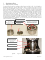
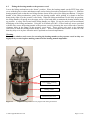
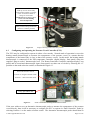
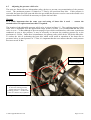
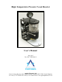
High-Temperature Pressure Vessel Reactor
User’s Manual
May 2005
Doc. Ref.: UM/0096/01
Applied Photonics Ltd
Unit 8 Carleton Business Park, Skipton, North Yorkshire BD23 2DE, United Kingdom
Tel +44 (0) 1756 708900 Fax +44 (0) 1756 708909 Web: www.appliedphotonics.co.uk
Contents
1.
Introduction
Page
3
2.
Safety
2.1
Electrical
2.2
High pressures and temperatures
3
3
3
3.
General description
3.1
High-temperature pressure vessel and support stand assembly
3.2
Heating mantle
3.3
Controller
5
5
8
9
4.
Operating procedures
4.1
Fitting the pressure vessel body
4.2
Fitting the heating mantle to the pressure vessel
4.3
Configuring and operating the controller
4.4
Connecting the controller to the heating mantle and pressure transducer
4.5
Adjusting the pressure relief valve
10
10
11
12
13
14
5.
Maintenance and inspection
5.1
Pipework and fittings
5.2
Pressure vessel body
5.3
Pressure vessel head
5.4
Heating mantle
15
15
15
15
15
Appendices
A1
Certificate of Conformity
© 2005 Applied Photonics Ltd
16
Page 2 of 16
1
Introduction
The four High-Temperature Pressure Vessel Reactor units to which this manual refers were designed and
manufactured by Applied Photonics Ltd for Nexia Solutions Ltd under contract number 4500384268 (2
Dec 2004 to 31 Jan 2005) and contract number 4500413679 (21 March to 15 April 2005). The units were
designed to a general specification provided by Nexia Solutions Ltd and are suitable for use on an open
bench, inside a fumehood or enclosed within a glovebox. Each unit has two independent pressure relief
devices to prevent over-pressurisation of the vessel (a relief valve and a precision burst disc) and two
independent methods of monitoring the internal pressure (an electronic pressure transducer and an
analogue pressure gauge). For glovebox use, the units have been designed so that only partial
disassembly is required for posting through a 10” diameter glovebox port. In consideration of the special
requirements of a glovebox environment, a number of additional safety features have been included to
minimise the risk of i) over-pressurising the glovebox in the event of one or both of the safety relief
valves venting gas from the pressure vessel, and ii) thermal damage to heat-sensitive glovebox
components, in particular the polymer gloves. These additional safety features are described in the
following sections of this manual.
This User’s Manual should be read in conjunction with the Technical File provided to Nexia Solutions
Ltd with the High-Temperature Pressure Vessel units. The Technical File provides complete design
information for the units including detailed engineering drawings, assembly instructions for certain subassemblies such as the heating mantle, electrical drawings, general arrangement drawings / images, and
certificates of conformity for certain components and devices. A comprehensive parts list is also included
with the Technical File.
2
Safety
2.1
Electrical
Certain parts of the High-Temperature Pressure Vessel Reactor (ie. the controller and the heating mantle)
contain electrical components operating at potentially lethal voltage and current levels. Always unplug
the instrument from the mains supply before carrying out any servicing of the instrument. Servicing of the
instrument should be carried out only by suitably qualified personnel. The instrument is designed as a
Class 1 electrical product and so must be connected to a safety earth ground via the mains supply lead.
For added safety, it is highly recommended that the controller is connected to the 230 VAC mains supply
using the lead provided with the controller and which is fitted with a 30 mA Residual Current Device
(RCD). It is recommended also that the controller is only connected to the mains supply when the
controller is properly connected to the heating mantle using i) the supplied flexible power cable
terminated with Lemo plug and socket, and ii) the thermocouple cable – proper connection is described
later in this manual.
Note on Portable Appliance Testing
The cartridge heaters used in the heating mantle have a relatively high leakage current to earth, the exact
figure varying from heater to heater. In view of this, an insulation impedance test could yield a value of
as low as 0.3 MΩ. This value is acceptable and has been taken into account in the electrical design of the
units.
2.2
High pressures and temperatures
All pressures mentioned in this User’s manual are gauge pressures. The pressure vessel and associated
pipework are designed to operate, under normal operating conditions, at pressures of up to 30 Bar at any
temperature in the range ~20°C (room temperature) to the maximum operating temperature of 600°C. In
order to allow for a significant safety margin, the maximum design pressure (ie. Safe Working Pressure)
of the vessel is 50 Bar @ 600ºC. Two independent pressure limiting devices are included in the design of
© 2005 Applied Photonics Ltd
Page 3 of 16
the pressure vessel; a burst disc which is designed to open if the pressure exceeds 37 Bar and a pressure
relief valve which may be set by the user to any pressure in the approximate range 20 Bar to 50 Bar.
Warning
If the system is pressurised to greater than ~30 Bar, the burst disc will be weakened which could
result in the burst disc activating (ie. bursting) at pressures less than the rated burst pressure of 37
Bar. Activation of the burst disc will require a replacement to be fitted. It is essential that only the
same type and rating of burst disc is fitted - contact the manufacturer if a replacement burst disc
is required.
The outlet of both the burst disc and pressure relief valve are fitted with a sintered metal filter (0.5 micron
pore size). The purpose of the filters is twofold; i) to prevent particulates escaping from the pressure
vessel, and ii) to limit the flow-rate of gas escaping from the pressure vessel (ie. to reduce the risk of
over-pressurising the glovebox in which the unit will ultimately be located) when either safety device
operates.
The heating mantle is designed to heat the pressure vessel to temperatures of up to 600°C. It is therefore
clear that the pressure vessel and other components in close proximity could be at elevated temperatures
and hence pose a risk to the user of burns to the skin should contact be made with these components. A
guard is supplied with the unit which is designed to prevent accidental contact with the hot components.
It is important that this guard is fitted to the unit whenever the pressure vessel is to be operated at elevated
temperatures. The pressure vessel will take a considerable period of time to cool from elevated
temperatures. Before starting to dismantle the pressure vessel body, it is vital that the user checks that the
vessel is not at pressure and/or elevated temperature.
Warning
To prevent damage to the units and to minimise the risk of personal injury, it is the responsibility of the
user to ensure that the following ratings are not exceeded:
Pressure Vessel Maximum Operating Pressure
= 30 Bar (gauge)
Pressure Vessel Maximum Operating Temperature
= 600°C
© 2005 Applied Photonics Ltd
Page 4 of 16
3
General description
3.1
High-temperature pressure vessel and support stand assembly
The support stand provides a platform on which the pressure vessel head, associated pipework and
pressure components (safety relief valves, pressure gauges, inlet/outlet ports, etc) are located. The
mechanical attachment to the pressure vessel head is designed for adequate strength whilst maintaining a
relatively low thermal conduction path between the vessel head and the support stand assembly. The
pressure vessel body is fitted to the vessel head using high-tensile (black steel) M8 x 40 hex head cap
screws (8-off). Two designs of pressure vessel body are included with each unit; the first (Pt. No. 1.01) is
designed to accommodate a silver-plated C-ring metal seal (Pt. No. 2.01) and the second (Pt. No. 1.02) is
designed to accommodate either a PTFE seal (Pt. No. 1.04) or a nickel-plated C-ring seal (Pt. No. 2.81).
The PTFE seal is suitable for vessel temperatures up to approximately 225°C whereas either of the metal
C-ring seals are suitable for temperatures up to the maximum rating for the pressure vessel (ie. 600°C).
The PTFE seal is re-useable to a limited extent whereas the metal C-ring seals are designed for single-use
only.
The support stand includes a lifting mechanism which is used to manually lift the heating mantle into
position and lock it in place. Further information on the correct procedure for securing the heating mantle
to the pressure vessel is given in section 4.2.
General views of the high-temperature pressure vessel and support stand assembly are given in figures 1
to 5.
Support stand assembly
Safety guard and 4-off
retaining screws
Heating mantle
Figure 1.
General view of the high-temperature pressure vessel unit
© 2005 Applied Photonics Ltd
Page 5 of 16
Analogue pressure gauge
Support stand
Pressure vessel head
Pressure vessel body
Heating mantle
Lifting mechanism for
heating mantle
Figure 2.
General view of the high-temperature pressure vessel unit with heating mantle removed.
Pressure vessel body
(with PTFE seal in place)
Guard and 4-off retaining screws
Sample holder and spacer rings
Figure 3.
General view of the high-temperature pressure vessel unit with vessel body removed.
© 2005 Applied Photonics Ltd
Page 6 of 16
Safety lock for lifting mechanism
(shown in “locked” position)
Lifting mechanism in “up” position
Lifting mechanism latch plate
Electrical lead from pressure transducer
Figure 4.
Left side view of unit with heating mantle fitted
Ball valve (gas inlet)
Needle valve (gas outlet)
Gas inlet port (for ¼” OD steel tube)
Gas outlet port (for ¼” OD steel tube)
Figure 5.
© 2005 Applied Photonics Ltd
Rear view of unit
Page 7 of 16
3.2
Heating mantle
The design and assembly of the heating mantle is described in detail in the Technical File supplied
separately to this User’s Manual. In brief, the heating mantle consists of a stainless steel heater body
located in a thermally insulated mantle within an outer aluminium can. The heater body contains six
cartridge heaters each rated at 150 Watts, 230 VAC, giving a total power of 900 Watts. One of the
cartridge heaters contains an embedded Type K thermocouple, connection to which is made via the
thermocouple chassis socket located as shown in figure 6. Electrical power to the cartridge heaters is
made via the power socket located as shown in figure 6. The outer aluminium can is finned and anodised
black to help to dissipate heat and hence maintain a relatively low temperature. When operating the
heating mantle at temperatures of greater than approximately 250°C, it is advisable to provide forced-air
convection to help dissipate heat build-up in the outer aluminium can. Tests have shown that with only a
modest air-flow, the temperature of the outer aluminium can remains less than 40°C even when the
heating mantle is operated at its maximum rated temperature of 600°C for prolonged periods. To prevent
over-heating of the heating mantle, two thermal fuses wired have been included in the design, both of
which are in thermal contact with the outer aluminium can. Activation of either or both thermal fuses will
interrupt electrical power to the cartridge heaters. One thermal fuse is of the “automatic reset” type and is
designed to cut electrical power to the heaters when the temperature of the outer aluminium can reaches
70°C and reconnect power when the temperature falls to 55°C. The second thermal fuse, which acts as a
back-up in the event of failure of the first thermal fuse, is of the “manual reset” type and is designed to
permanently cut electrical power to the heaters when the temperature of the outer aluminium can reaches
100°C. Should this fuse be activated, it will be necessary to return the heating mantle to the manufacturer
for inspection and servicing.
Lifting trunion (2-off)
Thermal insulation discs
Heater body and support ring
8-off M3 dome nuts (used to secure heater
body by compressing the thermal insulation
discs against the heater body support ring) –
see section 5.4 for further information.
Outer aluminium can
Thermocouple socket
Power socket for heaters
Figure 6.
Image of heating mantle
© 2005 Applied Photonics Ltd
Page 8 of 16
3.3
Pressure Vessel Controller (PVC)
The Pressure Vessel Controller (PVC) monitors and controls the temperature of the heaters in the heating
mantle and, if required, the temperature of the gas within the pressure vessel by means of an additional
(optional) thermocouple probe. The optional probe (Pt. No. 2.17) is inserted into the pressure vessel
using the spare ¼” BSPP port in the head of the vessel and the high-temperature sealing gland (Pt. No.
2.16). The PVC also monitors the pressure of the gas within the vessel via the electronic pressure
transducer.
The PVC may be configured in either of two operating modes – see section 4.3 for further details on this.
The PVC contains two fuses. The main fuse (5 Amp) is in the IEC switched mains input socket located
on left of the rear panel (see figure 8). Another fuse (1 Amp, Quick Blow) is used to protect the
electronic devices within the PVC and is located inside the PVC enclosure in a fuseholder on the DIN rail
(see figure 13, page12). Replacement fuses must be of the same type and rating.
Figure 7.
Image of front view of PVC
Figure 8.
Image of rear view of PVC
5 Amp
main fuse
Warning
The Pressure Vessel Controller MUST be connected to a protective earth via the mains power lead.
It is highly recommended also that the RCCD protected power lead supplied with the unit is used.
© 2005 Applied Photonics Ltd
Page 9 of 16
4
Operating procedures
4.1
Fitting the pressure vessel body
Two types of pressure vessel body are supplied with each unit; vessel body (Pt. No. 1.01) which utilizes a
silver-plated C-ring seal (Pt. No. 2.01) and vessel body (Pt. No. 1.02) which utilizes either a PTFE seal
(Pt. No. 1.04) or a nickel-plated C-ring seal (Pt. No. 2.81). Before fitting the vessel body to the vessel
head, it is important to ensure that the mating surfaces are scrupulously clean and the correct sealing
gasket is fitted. The sample holder and, if required, volume-reducing spacers, should be fitted inside the
vessel body (see figure 9). Lift by hand the vessel body and mate it up to the lower flange face of the
vessel head ensuring that the 4-off counter-bored M5 holes in the body flange align with the 4-off M5
clearance holes in the vessel head flange. Secure the vessel body to the head using 8-off M8 x 40 hightensile (black steel) hex head cap screws and M5 s/s plain washers (see figure 10). Tighten the M8
screws progressively and evenly until the flanges faces meet (this will be obvious by a sudden increase in
the torque required to tighten the screws). Do not tighten further. While tightening these screws, it is
recommended that the special C-spanner (Pt. No. 1.39) is used to prevent excess torque being transferred
to the 4-off vessel head securing pins.
Volume-reducing spacer
rings (5-off).
Each spacer has a volume
of approx. 17.5 ml.
Figure 9.
Pressure vessel body fitted
with PTFE sealing gasket
Sample holder
4-off counter-bored holes for the
black steel M5 x 25 socket head
cap screws used to fully secure
heating mantle to pressure vessel
Image of pressure vessel body, sample holder and volume-reducing spacer rings
8-off M8 x 40 high-tensile
(black steel) socket head
cap screws with s/s M8
plain washers
Pressure vessel head
Pressure vessel body
Figure 10.
© 2005 Applied Photonics Ltd
Image of pressure vessel body fitted to vessel head
Page 10 of 16
4.2
Fitting the heating mantle to the pressure vessel
Lower the lifting mechanism to the “down” position. Place the heating mantle on the PTFE base plate
cover with the power socket and thermocouple socket facing forwards as indicated in figure 11. Slide the
heating mantle back so that the two lifting trunions locate in the yoke of the lifting mechanism. Using the
handle of the lifting mechanism, gently raise the heating mantle while guiding it by hand so that the
heater body slides over the pressure vessel body. When the lifting mechanism is in the fully up position,
the lifting handle will spring in to the upper recess of the latch plate to maintain the heating mantle in the
up position. A safety lock located on the lifting handle (see figure 12) may be used to prevent accidental
dislodging of the lifting mechanism. Using the 4-off black steel M5 x 25 hex head cap screws provided
with the unit, secure the heating mantle to the pressure vessel by inserting the screws from above into the
clearance holes in the flange of the pressure vessel head. These screws only need to be tightened
sufficiently to hold the heating mantle firmly in place - do not overtighten these screws as there is a risk
that they may seize in place when the unit is operated at elevated temperatures.
Warning
Do not use stainless steel screws for securing the heating mantle to the pressure vessel as they are
highly likely to seize in place making removal of the heating mantle impossible.
Yoke of lifting mechanism
2-off trunions of heating
mantle
Heating mantle
PTFE base plate cover
Figure 11.
Image of heating mantle correctly aligned with lifting mechanism
© 2005 Applied Photonics Ltd
Page 11 of 16
4-off black steel M5 x 25 socket
head cap screws used to fully
secure heating mantle to pressure
vessel via clearance holes in
flange of vessel head.
NB Do not use s/s screws as s/s
screws can seize making
removal impossible
Safety lock for lifting mechanism
(shown in “locked” position)
Figure 12.
4.3
Image of heating mantle lifted into position
Configuring and operating the Pressure Vessel Controller (PVC)
The PVC may be configured to operate in either of two modes. Normal mode of operation is to use the
heating mantle thermocouple to measure the temperature of the pressure vessel (ie. assume that the
temperature of the heater body is close to that of the pressure vessel). In this mode, the heating mantle
thermocouple is connected to the PID temperature controller (digital display, front panel) using the
supplied “plug-to-socket” thermocouple lead. The Heater Protection Controller (analogue display, rear
panel) and its associated thermocouple input (front panel) are taken out of circuit by selecting the “0”
position on the mode selection switch, as illustrated in figure 13.
PVC mode selection switch:
Position 0 = Single Controller mode
Position 1 = Dual Controller mode
1 Amp, Quick Blow fuse
Figure 13.
Inside view of PVC showing mode selection switch
If the user wishes to use an alternative thermocouple probe to measure the temperature of the pressure
vessel directly, then it will be necessary to configure the PVC to operate in “Dual Controller” mode by
selecting Position 1 on the mode selection switch. The alternative thermocouple probe should then be
© 2005 Applied Photonics Ltd
Page 12 of 16
connected to the “PID Controller T/C Input” (front panel). In this mode, it is essential that the heaters are
protected from overheating and so the heating mantle thermocouple should be connected to the “Heater
Controller T/C Input” (front panel) using the supplied “plug-to-plug” thermocouple lead and the “Heater
Protection Controller” (rear panel) is set to a temperature of typically 50°C higher than the required
temperature of pressure vessel (ie. as set by the “Vessel Temperature” PID controller on the front panel).
Warning:
The “Heater Protection Controller” should never be set to a temperature of greater than 650°C and
the “Vessel Temperature” PID controller should never be set to a temperature of greater than
600°C.
Operation of the “Vessel Temperature” PID controller, the “Vessel Pressure” readout controller, and the
“Heater Protection Controller” is described in the relevant manufacturer’s instructions which are included
with the Technical File documentation provided with the High-Temperature Pressure Vessel Reactors.
4.4
Connecting the Pressure Vessel Controller to the heating mantle and pressure transducer
The normal mode of operation for the Pressure Vessel Controller (PVC) is the “Single Controller” mode
and the electrical connections to the PVC are as illustrated in figure 14.
Warning
It is strongly recommended that the PVC is connected to the heating mantle before mains power is
supplied to the unit.
Heating mantle
thermocouple connected to
“PID Controller T/C Input”
Lead from pressure
transducer
Heater power lead
connected to rear
panel of PVC
Figure 14.
Image illustrating the electrical connections between the PVC, heating mantle and pressure transducer
when configured in “Single Controller” mode (see section 4.4).
© 2005 Applied Photonics Ltd
Page 13 of 16
4.5
Adjusting the pressure relief valve
The units are fitted with two independent safety devices to prevent over-pressurisation of the pressure
vessel. The maximum pressure is limited to 37 Bar by the precision burst disc. If this pressure is
exceeded, the burst disc will open and allow the gas within the pressure vessel to vent to the outside via a
sintered metal filter. It will then be necessary to replace the burst disc.
Warning
It is vitally important that the same type and rating of burst disc is used
manufacturer if a replacement burst disc is required.
-
contact the
The location of the adjustable pressure relief valve is given in figure 15. The cracking pressure of the
relief valve is adjustable over the approximate range 20 bar to 50 Bar. It is recommended that the relief
valve is set to ~ 30 Bar although to prevent seepage of gas which could interfere with some experiments
conducted at near to this pressure, it may be necessary to increase the cracking pressure up to the
maximum of ~50 Bar. Under these circumstances, the primary safety relief device will be the burst disc.
To reduce the risk of weakening the burst disc which could result in operation of the burst disc at
pressures below its rated pressure of 37 Bar, it is important that the user ensures that the vessel pressure
does not exceed 30 Bar.
Precision burst disc
Pressure transducer
Sintered metal filters
Adjustable pressure relief valve.
To increase cracking pressure,
tighten head screw clock-wise
Cracking pressure = ~50 Bar when
relief valve head is fully tightened
Figure 15.
View of pipework showing location of pressure relief valve, burst disc and associated components
© 2005 Applied Photonics Ltd
Page 14 of 16
5
Maintenance and inspection
5.1
Pipework and fittings
All pressurised components should be periodically inspected for damage and/or leaks. If a leak is
suspected from any of the components, contact the manufacturer for advice on how to repair the leak. If
any component appears to be damaged or is malfunctioning in some way, the entire unit should be
returned to the manufacturer for servicing.
5.2
Pressure vessel body
The M8 threaded holes (8-off) should be periodically checked for wear using the supplied thread gauge.
If the “no-go” end of the thread gauge can be screwed into any of the M8 threaded holes by more than
approx. one turn, the pressure vessel should be immediately removed from service and a replacement
obtained from the manufacturer.
5.3
Pressure vessel head
Periodically inspect the 4-off attachment pins to the pressure vessel head (ie. modified s/s M8 x 40 grub
screws, Pt. No. 1.22) to ensure that they are adequately tight (use an appropriate Allen key to tighten). If
any of the attachment pins become bent, contact the manufacturer for a replacement and instructions on
how to fit the new part.
5.4
Heating mantle
The heater body (and associated support ring) should be checked before each use to ensure that it is not
loose inside the thermal insulation. If it is found to be loose, it will be necessary to tighten the 8-off M3
dome nuts (located on the top cover of the heating mantle) while the heating mantle is fitted to the
pressure vessel (to ensure correct alignment of the heater body with respect to the heater mantle). It is
important not to over-tighten the M3 dome nuts – they should only be tightened as necessary to
adequately secure the heater body. Excessive tightening may permanently damage the internal
components of the heating mantle.
The heating mantle should be periodically checked for damage, in particular the thermal insulation discs
which are quite fragile. It is acceptable for the insulation discs to have some cracks but they should not
be loose or have significant amounts of material missing. If significant damage is observed, the heating
mantle should be returned to the manufacturer for servicing.
© 2005 Applied Photonics Ltd
Page 15 of 16
Appendix A1
Certificate of Conformity
Applied Photonics Limited
Unit 8 Carleton Business Park
Skipton North Yorkshire
BD23 2DE United Kingdom
EC
Declaration of Conformity
Applied Photonics Ltd declares that the product listed below has been designed and manufactured in
compliance with the relevant standards as follows:
Product name:
High-Temperature Pressure Vessel Reactor and ancillary equipment
Model Number:
0096/A, 0096/B, and 0096/C
Electrical Safety
This device conforms with the principal safety objectives of the European Directive 73/23/EEC, as
implemented by the Electrical Equipment (Safety) Regulations 1994, by application of the following
standard: BS EN 61010-1:2001.
Pressure equipment safety
This device conforms with the principal safety objectives of the European Directive (97/23/EEC), as
implemented by the Pressure Equipment Regulations (1999), by application of Sound Engineering
Practice (SEP). NB. CE marking is not required in this instance.
Electro-Magnetic Compatibility
This device conforms with the principal objectives of the European Directive (89/336/EEC) as amended
by 91/31/EEC and 93/68/EEC, as implemented by The EMC Regulations (SI 1992 No. 2372 and
amendment SI 1994 No. 3080), by application of the following standard: BS EN 61326-1:1997
Year of affixation of the CE Marking:
2005
Signed:
Name:
Andrew I. Whitehouse
Title:
Managing Director
Place:
Applied Photonics Ltd, Unit 8 Carleton Business Park, Skipton, North Yorkshire BD23
2DE, United Kingdom
Date:
31 May 2005
© 2005 Applied Photonics Ltd
Page 16 of 16