1
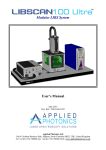
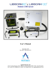
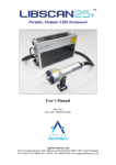
LIBSProbe 100S Underwater LIBS System
Model No. 0164
User’s Manual
June 2009
Doc. Ref.: UM/0164/00
Applied Photonics Ltd
Unit 8 Carleton Business Park, Skipton, North Yorkshire BD23 2DE, United Kingdom
Tel +44 (0) 1756 708900 Fax +44 (0) 1756 708909 Web: www.appliedphotonics.co.uk
Contents
1.
Introduction
Page
3
2.
Safety
2.1
Laser radiation
2.3
Electrical
3
3
4
3.
General description
3.1
Overview
3.2
The laser module
3.2.1 The fibre launch optics enclosure
3.2.2 The fibre-optic cable spool
3.2.3 The fibre-optic umbilical manifold
3.3
The submersible LIBS probe and umbilical
3.3.1 General description
3.3.2 The laser safety cover tube
3.3.3 Assembly views of submersible LIBS probe
3.4
ICE 450 laser power supply module
3.5
The submersible remote monitor housing
3.6
Installing LIBSProbe into transit case
5
5
6
6
8
9
9
9
11
12
15
15
18
4.
Operating procedure
20
5.
Shut-down procedure
22
6.
Maintenance and inspection
22
7.
Shipping and storage
22
Appendices
A1
Certificate of Conformity
© 2009 Applied Photonics Ltd
23
Page 2 of 23
1
Introduction
The LIBSProbe 100S Underwater LIBS System is designed to be a highly versatile product suitable for
use either in a laboratory environment or in the field. The gas-purge LIBS probe design allows for LIBS
analysis of solid materials to be carried out underwater or in air. This particular model of LIBSProbe
system utilises a 40 metre long flexible umbilical between the laser system and the LIBS probe, thereby
allowing deployment of the probe in a marine environment to a depth approaching 40 metres. At this
depth, the ambient pressure is nominally 5 Bar absolute (4 Bar gauge pressure) and so the LIBSProbe
system is designed to allow operation of the probe at any depth up to 40 metres sea water.
2
Safety
2.1
Laser radiation
LIBSProbe contains a high-power Q-switched Nd:YAG laser (Class 4) and so it is imperative that it is
operated only by suitably trained and experienced persons who are fully aware of the hazards inherent to
this type of high-power laser equipment. It is imperative also that, prior to using the equipment, an
appropriate risk assessment is conducted in such a way as to take account of the proposed use of the
equipment, the environment in which the equipment is to be operated, and how its use may affect people
who are not directly involved with the use of the equipment.
LIBSProbe is designed to meet the laser safety requirements of the relevant European standards (BS EN
60825) and USA standards (ANSI Z136.1 – 2007). It is important to be aware that LIBSprobe is a Class
4 Laser Product and so, by definition, the instrument poses a risk of personal injury (eye, skin injury)
and poses a fire risk. As with all Class 4 laser products, appropriate safety precautions must be taken as
identified via a suitable risk assessment conducted by the user in consultation with a suitably qualified
and experienced Laser Safety Officer.
The most significant hazard relating to exposure of personnel to the laser radiation is eye injury since
direct or scattered laser radiation produced by LIBSProbe can cause serious and permanent injury to the
eyes including blindness - such injury may be instantaneous. Precautions must be taken to avoid
exposure of personnel to hazardous levels of laser radiation. Such precautions may include the setting up
of a temporary or permanent laser controlled area (eg. a laser laboratory). Other measures may also be
necessary, as determined by appropriate and thorough assessment of the risks (ie. a risk assessment)
conducted by the personnel responsible for the safe use of the LIBSProbe system. Consult the manual
supplied with the laser (see Quantel Big Sky CD-ROM) for further guidance on the safe use of the laser.
© 2009 Applied Photonics Ltd
Page 3 of 23
IMPORTANT
•
READ and UNDERSTAND both this User’s Manual and the instructions provided by the
manufacturer of the laser (Quantel Big Sky) before operating LIBSProbe.
•
NEVER allow unauthorised and/or untrained personnel operate LIBSProbe.
•
ALWAYS use appropriate laser safety protective eyewear when operating LIBSProbe in “openbeam” configuration – you should seek advice from your Laser Safety Officer on this matter.
•
ALWAYS switch the laser off when not in use and remove the key from the keyswitch of the laser
power supply to prevent unauthorised activation.
•
NEVER operate LIBSProbe in areas where explosive gas mixtures may be present.
•
NEVER operate LIBSProbe with any access cover removed.
•
ALWAYS thoroughly inspect LIBSProbe for damage prior to use. Do not use if any component
is found or suspected to be damaged.
•
NEVER point the LIBS probe at a person (even with laser switched off), especially towards the
eyes, even if the person is wearing laser safety eyewear. The laser should be considered
“active” unless the laser power supply is deactivated and the laser safety cover tube is fitted
to the probe.
Laser safety cover tube
CAD image of submersible LIBS probe with laser safety cover tube fitted
2.2
Electrical
The laser head and laser power supply of LIBSProbe contain electrical circuits operating at potentially
lethal voltage and current levels. Before removing any access covers, isolate mains power from the laser.
Consult the manual supplied with the laser for further guidance on the safe use of the laser.
© 2009 Applied Photonics Ltd
Page 4 of 23
3
General description
3.1
Overview
The main components of LIBSProbe (model 0164) are illustrated in the following figures.
CAD view illustrating ICE laser power supply module (left) and laser module (right) with probe umbilical in foreground
Image showing ICE 450 power supply module and laser module (top right) with probe umbilical in foreground
© 2009 Applied Photonics Ltd
Page 5 of 23
3.2
The laser module
The laser module (illustrated below) contains the laser head and associated optical components for
launching the laser radiation into the fibre-optic cable and collecting the return plasma light for
transmission to an optical spectrograph (not supplied with LIBSProbe model 0164). There are three main
components within this module: i) the fibre launch optics enclosure, ii) the fibre-optic cable spool, and iii)
the fibre-optic umbilical manifold.
Fibre launch
optics enclosure
Fibre-optic
umbilical manifold
Fibre-optic
cable spool
CAD view of laser module illustrating main components
3.2.1
The fibre launch optics enclosure
Pierced mirror at 45 deg
to laser beam – used to
reflect plasma light
towards 2” lens system
Condensing
lens
Fibre-optic chuck
Laser beam
45-deg mirrors
XY translation stage
2” diameter lens system
used to focus plasma light
into the spectrometer
fibre-optic cable
Laser head
Fibre-optic SMA
connector in XY
translation stage
Spectrometer fibreoptic cable fits here
CAD view of fibre launch optics enclosure
© 2009 Applied Photonics Ltd
Page 6 of 23
Bare fibre-optic
cable (with
buffer jacket)
XY
translation
stage
Fibre-optic cable
(with buffer
jacket stripped)
Approx. 100 mm
(distance Z)
(Plasma light)
fibre-optic SMA
connector in XY
translation stage
CAD image of fibre launch optics enclosure
Training on how to prepare, install and align the optical fibre has been provided during commissioning of
the LIBSProbe instrument. The optical fibre is an all-silica, High-OH, UV-grade fibre with a core
diameter of 550 microns. The product code for the fibre is HCG-M0550T. The cleaved end face of the
fibre should be positioned approx. 100 mm from the laser beam condensing lens, as illustrated above.
Optimum alignment is achieved by reducing the laser beam energy to approx. 10 mJ and monitoring the
output energy at the probe using an appropriate energy meter. It may be necessary to adjust both the XY
translation stage and the Z distance (between fibre end and condensing lens). Correct alignment will be
achieved when the output energy is at a maximum and there is no sign of plasma formation at the cleaved
face of the fibre or any point behind the cleaved face of the fibre (eg. the buffer jacket, the fibre-optic
chuck).
Correct alignment of the SMA terminated optical fibre (used to transmit plasma light to spectrometer) is
best achieved by directing the output of a CW light source (eg. spectral lamp such as a Hg lamp) into the
aperture of the LIBS probe and monitoring the collected light using a suitable spectrometer. If a small
diameter fibre-optic cable is used to connect the fibre launch module to the spectrometer, then the effects
due to chromatic aberration will be more noticeable. These effects are due to the use of refractive optics
(lenses) in the plasma light collection optical system (ie. the pierced aluminium mirror and three fusedsilica 2” diameter lenses). Chromatic aberration has been minimised as far as is reasonably practicable in
the design of the lens system, however, it will still be necessary to adjust the position of the spectrometer
fibre (using the XY translation stage) to maximise signal intensity in the desired region of the UV-VisNIR spectrum.
© 2009 Applied Photonics Ltd
Page 7 of 23
3.2.2
The fibre-optic cable spool
It is inevitable that the laser input end of the fibre will at some point suffer catastrophic damage (eg. from
excess laser energy, poor alignment, degradation of fibre, etc) and so occasionally will need to be cut
back and re-cleaved. This means that a short length (typically 100 mm to 200 mm) of fibre will be
consumed each time the fibre is re-cleaved and so if there was not any “spare” fibre, it would be
necessary to replace the whole length of fibre each time the fibre input end was re-cleaved. To overcome
this problem, the LIBSProbe instrument is designed so that an additional several metres of fibre is
available for re-cleaving. This extra length of fibre is stored on the cable spool. To facilitate storage of
varying lengths of fibre, the spool is split into two semi-circular components the lower of which is
mounted on an adjustable base so that the distance between the two halves may be adjusted. This
provides a simple and convenient means of adjusting the “size” of the spool in order to take up slack in
the fibre.
Note: The length of “spare” fibre is vulnerable to damage and so great care should be exercised when
carrying out any adjustments or maintenance within the laser module, in particular the area just above the
fibre-optic cable spool where the bare fibre enters the cable glands.
Fibre-optic cable
spool split into two
components
Up / down
adjustment of lower
half of spool
CAD views of fibre-optic cable spool
“Spare” length of bare optical fibre. The fibre is very
vulnerable so great care should be exercised when
conducting any maintenance work in this area
Image showing “spare” fibre stored on fibre-optic cable spool
© 2009 Applied Photonics Ltd
Page 8 of 23
3.2.3
The fibre-optic umbilical manifold
The purpose of the fibre-optic manifold is to:
•
•
•
provide a means of connecting an external gas supply to the umbilical
provide a gas-tight outlet gland for the bare fibre (on the spool side of the umbilical)
provide a robust mechanical attachment point for the umbilical
PCL Safety Coupler
quick-connect gas port
(with non-return valve)
Fibre-optic
umbilical manifold
Gas-tight outlet
gland for bare fibre
(RS 390-066)
Various views of the fibre-optic umbilical manifold
3.3
The submersible LIBS probe and umbilical
3.3.1
General description
The submersible LIBS probe contains the optics needed to focus the laser radiation emitted by the optical
fibre to a spot size of typically 300 microns diameter. The focal plane of the output beam is set to
coincide with the plane of the probe output aperture. It may be necessary to adjust the position of the
output aperture (by slackening the locking ring and turning the probe aperture clockwise or counterclockwise as necessary) so as to achieve the desired focussing conditions for optimum LIBS analysis
performance. A degree of experimentation will be required to achieve this. When correctly adjusted, the
laser beam will be correctly focussed on the sample surface when the sample is placed in direct contact
with the probe aperture. Best analytical performance is obtained when the probe is held normal to the
surface of the material being analysed, although the design of the probe allows some latitude in alignment
(ie. typically 10 degrees from normal).
Locking ring
Probe output
aperture body
Umbilical (¾” hydraulic hose,
40 metres)
3/4R2T x 40m Ftd S/S
females (Swift Hydraulics)
Probe output aperture
CAD view of submersible LIBS probe with flexible umbilical
© 2009 Applied Photonics Ltd
Page 9 of 23
Image of submersible LIBS probe
CAD view of submersible LIBS probe illustrating method of attachment of handle
The submersible LIBS probe is of APL’s gas-purge design, which means that gas fed via the umbilical is
allowed to exit the probe via the output aperture in such a way that i) water is prevented from entering the
probe and ii) the laser beam can interact with the sample surface in a gas environment rather than a liquid
environment. Note that during operation a steady stream of gas bubbles will be emitted from the output
aperture even when the probe is placed in contact with the material being analysed (ie. there is no need to
try to obtain a gas-tight seal between the probe and the material being analysed – in fact it is undesirable
to try to achieve a gas-tight seal).
The model 0164 LIBSProbe 100 instrument is equipped with a ~40 metre umbilical which connects the
probe to the laser module. The umbilical has two primary functions: i) to provide mechanical protection
for the optical fibre, and ii) to provide a means of supplying gas to the submersible LIBS probe. The
umbilical used in this model LIBSProbe is essentially a length of ¾” bore hydraulic hose with stainlesssteel fittings at each end. Hydraulic hose was chosen for use as an umbilical since we have used similar
hydraulic hose in previous applications of fibre-optic LIBS where a high level of mechanical strength and
robustness was required. Additionally, the hydraulic hose has desirable properties in terms of bend radius
(ie. the inherent stiffness of the hydraulic hose is such that bending the fibre-optic beyond its minimum
bend radius is highly unlikely).
© 2009 Applied Photonics Ltd
Page 10 of 23
3.3.2
The laser safety cover tube
A laser safety cover tube is supplied with the LIBSProbe instrument. The cover tube acts as a laser
aperture safety shutter (in order to meet Class IV laser product design standards) but also acts as a means
of protection for the LIBS probe against mechanical damage when not in use. Additionally, the safety
cover tube is equipped with a built-in reference sample (as illustrated below) which provides a convenient
means of testing the LIBS instrument even when the probe is submerged. Three interchangeable reference
samples are provided – stainless steel, aluminium alloy and phosphor bronze. Note that the flow of gas
exiting the probe is not restricted by the safety cover tube – the gas will exit from the small gap which
exists between the cover tube and the probe handle.
Removable
probe handle
Body of safety cover
tube (green nylon)
The safety protective
tube is secured in place
via two grub screws
located on either side of
the handle
Interchangeable reference
standard – screws into
stainless steel endcap of
safety cover tube
CAD image of LIBS probe with laser safety cover tube fitted
Grub screws used to secure
laser safety cover tube to
probe handle
Locating dowel pins
Qty 2
CAD image of LIBS probe illustrating method of attachment of laser safety cover tube
Interchangeable
calibration / reference
standards –
Qty 1 Phosphor bronze
Qty 1 Aluminium alloy
Qty 1 Stainless steel
CAD image of laser safety cover tube illustrating interchangeable calibration / reference standards
© 2009 Applied Photonics Ltd
Page 11 of 23
3.3.3
Assembly views of the submersible LIBS probe
The following diagrams illustrate the various components of the submersible LIBS probe.
Exploded view of LIBS probe
LIBS probe parts list
Item #
1
2
3
4
5
6
7
8
9
10
11
Part Number
0163-05-10A
0163-05-06A
0163-05-14
0163-05-15
0163-05-16
0163-05-17
0163-05-19
RS 290-3664
RS 812-033
RS 723-955 (nylon tube)
3/4BSP S/S bulkhead
(Swift Hydraulics)
40 x 2.5 mm N70
© 2009 Applied Photonics Ltd
Description
Rear lens assembly (brass body)
Front lens assembly (brass body)
Locking ring
Probe body (Delrin plastic, black)
Probe aperture (316 stainless steel)
Locking ring (316 stainless steel)
Rear flange body (316 stainless steel)
Pneumatic non-return valve
Pneumatic bulkhead adaptor (4 mm)
Note: short length of 4 mm OD nylon tube (2.5 mm bore)
between items 8 and 9
¾” BSP S/S bulkhead adaptor
(shortened to suit item 7)
40 mm ID 2.5 mm section O-ring (nitrile)
Qty
1
1
1
1
1
1
1
1
1
1
1
Page 12 of 23
Exploded view of rear lens assembly
LIBS probe rear lens assembly
Item #
1
2
3
4
5
6
7
8
9
10
Part Number
0163-05-09
CVI-BICX-25.4-38.1-UV
0163-05-25
24 x 1.5 mm N70
0163-05-03
0163-05-13
0163-05-20
3 x 1.5 mm N70
0163-05-24
30 x 2.5 mm N70
© 2009 Applied Photonics Ltd
Description
Rear lens body (brass)
UV-grade fused silica condensing lens
Retaining ring (brass)
24 mm ID 1.5 mm section O-ring (nitrile)
Shortened SMA bulkhead adaptor
Rear flange body (aluminium)
Spacer tube (aluminium)
3 mm ID 1.5 mm section O-ring (nitrile)
Fibre-optic ferrule sealing gland (aluminium)
30 mm ID 2.5 mm section O-ring (nitrile)
Qty
1
1
1
2
1
1
1
1
1
1
Page 13 of 23
Exploded view of front lens assembly
LIBS probe front lens assembly
Item #
1
2
3
4
Part Number
0163-05-04
CVI-BICX-19.1-35.2-UV
16 x 1.5 mm N70
0163-05-07
Description
Front lens body (brass)
UV-grade fused silica condensing lens
16 mm ID 1.5 mm section O-ring (nitrile)
Retaining ring (brass)
Qty
1
1
2
1
Important
It is strongly recommended that the umbilical end of the submersible LIBS probe is not dismantled unless
absolutely necessary since the delicate optical fibre which runs through the umbilical and connects with
the rear lens assembly is very easily damaged when the probe is dismantled. If the optical fibre is
damaged at the probe end of the umbilical, it will be necessary to replace the entire length of fibre. In
view of this, we recommend that you contact us before attempting to disassemble the rear section of the
submersible LIBS probe.
Note: Special tools are required to disassemble / reassemble the LIBS probe internal assemblies and
components – these tool are supplied with the LIBSProbe system.
© 2009 Applied Photonics Ltd
Page 14 of 23
3.4
ICE 450 laser power supply module
See manufacturer’s instructions for description of the ICE 450 laser power supply and cooling group unit.
The ICE 450 power supply is mounted inside the framework of the module. Vibration-isolation mounts
are used to minimise shock and vibration being transmitted through the module frame to the ICE 450
power supply.
CAD image of ICE 450 laser power supply module
3.5
The submersible remote monitor housing
The LIBSProbe instrument is supplied with a submersible remote monitor housing, a ~42 m length of
underwater cable / umbilical, and a VGA-Video converter including associated power supply and
connecting leads. The remote monitor allows the diver operator of the LIBS probe to view the screen
data produced by the system computer during a LIBS measurement. The submersible housing also
features a “fail safe” switch (located on rear of housing) which must be depressed before the laser can be
activated. Should the diver operator let go of the housing for any reason, the switch springs to the “off”
position thereby deactivating the laser.
CAD image of submersible remote monitor housing (left) and image of underwater connecting cable / umbilical (right)
© 2009 Applied Photonics Ltd
Page 15 of 23
“Fail safe” switch for laser
Lever must be depressed for
laser operation
CAD image illustrating “fail safe” switch on rear of submersible remote monitor housing
A breakout connector box is fitted to the “dry” end of the underwater cable / umbilical. The following
schematic diagram illustrates how the remote monitor is connected to the system computer. The interlock
lead should be connected to the “Interlock In” BNC port on the front panel of the ICE 450 laser power
supply.
5.6” colour LCD monitor
Schematic diagram illustrating electrical connections between submersible remote monitor and computer etc.
Note: All components on the breakout box end of the submersible cable / umbilical, including the
breakout box itself, are not waterproof and so must be kept dry.
© 2009 Applied Photonics Ltd
Page 16 of 23
Submersible PC monitor housing
Item #
1
2
3
4
5
6
7
8
9
10
11
12
13
14
15
Part Number
0164-08-03
0164-08-02
0164-08-04
0164-08-05
RS 105-8274
0164-08-01
210.9 x 4 mm N70
208.9 x 3 mm N70
215.3 x 3 mm N70
Stock component
0164-08-11A
0164-08-17
RS 456-490
Euroswitch V3 GRP N/OPEN
& MA-4S (M6 x 45)
Longvale Ltd
0164-08-20
© 2009 Applied Photonics Ltd
Description
Base plate
Tubular body
Acrylic window
Acrylic window cover plate
Male-female threaded spacer
Monitor support bracket 1
210.9 x 4 mm section O-ring (nitrile)
208.9 x 3 mm section O-ring (nitrile)
215.3 x 3 mm section O-ring (nitrile)
M3 x 16 s/s skt hd cap screw
“Fail-safe” switch body
Protective shroud (for electrical connector)
Polyamide handle
Magnetic switch and actuator
Qty
1
1
1
1
4
1
1
1
1
8
1
1
2
1
Monitor support bracket 2
1
Page 17 of 23
3.6
Installing LIBSProbe into transit case
The laser module and the ICE 450 power supply module are located inside the transit case as illustrated in
the following image. Location pins at the bottom of the transit case are used to correctly locate each
module. The umbilical is coiled up and stored as illustrated.
Image showing location of laser module, ICE 450 module and fibre-optic umbilical inside transit case
The plasma light fibre optic cable and the electrical lead to the remote control box of the laser are fed
through the port in the top cover plate as illustrated below. Strain relief is achieved by using a cable clip
to secure the cables as shown. Note that the cable port also acts as a ventilation port – a fan filter cover is
fitted to this port to allow free flow of air (see subsequent images).
Image showing location of cable port in top cover
© 2009 Applied Photonics Ltd
Page 18 of 23
Fit the fan guard to the port as illustrated in the following two images.
Image showing lower section of fan guard fitted to cable port in top cover
Image showing “snap fit” fan cover fitted to cable port in top cover
Image showing laser remote control box in its storage position on the top cover plate.
© 2009 Applied Photonics Ltd
Page 19 of 23
Ventilation fan
(Air out)
“Dummy” fan cover
over cable port
(Air in)
Image showing LIBSProbe components installed inside transit case
Important
The ventilation fan is active whenever power is fed to the top cover panel of the LIBSProbe system. The
purpose of the ventilation fan is to provide an adequate flow of air to the ICE 450 laser power supply. Air
is expelled via the ventilation fan (right of image) and drawn into the unit via the “dummy” fan port (left).
The “dummy” fan port also acts as a cable entry port for the optical fibre and the electrical lead to the
laser remote control box.
Under no circumstances should the ventilation ports be obstructed. The ventilation fan must be operating
whenever the LIBSProbe system is switched on. If the fan does not come on when power is connected to
the inlet on the top cover plate, then the LIBSProbe system should be isolated from the power source and
the fault rectified. If in doubt, consult Applied Photonics Ltd.
4
Operating procedure
Step 1
LIBSProbe should first be checked for obvious signs of damage, loose fixings, missing
components, etc prior to use. If any of the components of the instrument are found to be of suspect
condition, take remedial action before assembling and using the instrument. Of particular importance are
the safety critical components such as the “fail safe” switch on the remote monitor housing. Seek advice
from the manufacturer if necessary. Do not operate LIBSProbe with any of the covers removed.
Step 2
Connect the 100 – 240 VAC power cord to the power inlet located on the top cover.
Step 3
Using the supplied BNC-to-BNC cable, connect the “Laser Interlock” port on the remote
monitor breakout box to the “Interlock In” port on the top cover.
Step 4
Using the supplied BNC-to-BNC cable, connect the “Trigger Out” port on the top cover to
the “Trigger In” port on your spectrometer (spectrometer not supplied with LIBSProbe system).
Step 5
Connect an external inert gas supply (Argon, Helium, Nitrogen, Air) to the Quick-Connect
port on the umbilical manifold. The gas pressure should be set to approx. 1 BarG (bar gauge pressure)
above the ambient pressure of the environment where the LIBS probe is to be deployed. Accordingly,
when the LIBS probe is deployed above water (eg. in a laboratory), the gas pressure should be set to
approx. 1 BarG. If the probe is to be deployed underwater to a maximum depth of 40 metres, the pressure
© 2009 Applied Photonics Ltd
Page 20 of 23
should be set to 5 BarG. For shallower depths, the gas pressure should be set according to the following
formula:
Gas pressure (BarG) = 1 + (Maximum depth of seawater in metres / 10)
Eg:
maximum depth = 30 metres, the gas pressure should be set to 4 BarG
maximum depth = 15 metres, the gas pressure should be set to 2.5 BarG
WARNING - the gas supply MUST be externally regulated to restrict pressure to a maximum of 5
BarG. DO NOT USE FLAMMABLE GASES!
Note: During underwater deployment of the LIBS probe, there must always be a steady stream of gas
bubbles exiting from the probe aperture. If there is not, the probe will flood with water.
Step 6 Activate laser by operating the remote control box (see instructions supplied with laser).
Step 7 With the laser switched on (coolant water flowing, but laser flashlamp not yet activated), check
for correct operation of the “fail safe” switch by observing the “Interlock” light on the front panel of the
laser power supply remote control box and releasing the “fail safe” switch on the rear of the remote
monitor housing. If the interlock is working correctly, the “Interlock” light should flash when the “fail
safe” switch is released and constantly illuminated when the “fail safe” switch is depressed. If the
interlock is found not to be operating correctly, check electrical connections and, if necessary, contact
Applied Photonics Ltd for further guidance. Warning – do not operate LIBSProbe if the “fail safe”
switch is not functioning correctly.
Step 8 Place a sample of material (eg. a metal block) in direct contact with the aperture of the LIBS
probe. Using the laser remote control box (refer to laser manufacturer’s instructions), the laser beam may
now be fired by i) first activating the flashlamp and ii) then activating the Q-Switch. If the sample
material is located at or near to the focal plane of the laser beam, a laser-induced plasma will be produced
on the surface of the sample. It may be necessary to adjust the position of the aperture cover to obtain
correct positioning of sample surface.
Fault warning light
View of front panel of laser power supply remote control box
© 2009 Applied Photonics Ltd
Page 21 of 23
Step 9 After successfully testing LIBSProbe, it is now ready for use. Measurement conditions such as
Nd:YAG laser pulse energy and position of sample surface with respect to laser beam focal plane will
need to be adjusted to suit the requirements of the experiment.
5.
Shut-down procedure
Step 1
Switch off laser power supply and isolate from mains electrical supply.
Step 2
Fit the laser safety cover tube to the LIBS Probe
Step 3
Switch off and disconnect gas supply
Step 4.
If the LIBSProbe system has been used in a marine environment, wash all seawater from
submersible components. Note: do not submerge or water wash / spray the LIBS probe unless the gas
supply is switched on. Failure to follow this procedure will result in water entering the probe with
consequential damage to internal components.
6.
Maintenance and inspection
LIBSProbe should be periodically inspected for signs of damage or wear and tear. Of particular
importance are the safety features including the “fail safe” switch on the rear of the remote monitor
housing. If any damage to safety critical components is observed or suspected, LIBSProbe should be
temporarily removed from service until the fault is rectified. For maintaining and inspecting the Quantel
Big Sky laser, the documentation supplied with the laser should be consulted. If in any doubt, contact
Applied Photonics Ltd for further advice on maintenance and inspection of the product.
7.
Shipping and storage
The ICE 450 laser power supply and the laser head (located within the laser module) MUST be drained of
coolant water if there is any possibility of the unit being exposed to temperatures below 4 Celsius.
Failure to do so could result in serious damage to the laser head and/or the laser power supply. The laser
manufacturer’s instructions should be followed for draining coolant water from the laser power supply
and the laser head.
© 2009 Applied Photonics Ltd
Page 22 of 23
Appendix A1
Certificate of Conformity
Applied Photonics Limited
Unit 8 Carleton Business Park
Skipton North Yorkshire
EC
Declaration of Conformity
BD23 2DE United Kingdom
Applied Photonics Ltd declares that the product listed below has been designed and manufactured in
compliance with the relevant standards as follows:
Product name:
LIBSProbe Model 0164 underwater LIBS system
Model Number:
0164
Laser product safety
This device conforms with the principal objectives of safety of laser products by application of the
following standards: PD IEC TR 60825-14:2004 and BS EN 207:1999
Electrical Safety
This device conforms with the principal safety objectives of the European Directive 73/23/EEC, as
implemented by the Electrical Equipment (Safety) Regulations 1994, by application of the following
standard: BS EN 61010-1:2001.
Electro-Magnetic Compatibility
This device conforms with the principal objectives of the European Directive (89/336/EEC) as amended
by 91/31/EEC and 93/68/EEC, as implemented by The EMC Regulations (SI 1992 No. 2372 and
amendment SI 1994 No. 3080), by application of the following standard: BS EN 61326-1:2006
Year of affixation of the CE Marking:
2009
Signed:
Name:
Andrew I. Whitehouse
Title:
Managing Director
Place:
Applied Photonics Ltd, Unit 8 Carleton Business Park, Skipton, North Yorkshire BD23
2DE, United Kingdom
Date:
June 2009
© 2009 Applied Photonics Ltd
Page 23 of 23