1
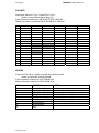
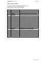
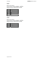
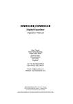
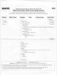
Velocity Drive Module
User Manual
Manual Revision 1.5
Drive Software Version 4.3.04/4.3.05
Kinesys Software Version 3.1.4
kinesys
Page 2 of 29
velocity user manual
velocity user manual
kinesys
Kinesys Projects Limited accepts no liability for any consequences resulting from
inappropriate, negligent or incorrect installation of the equipment.
The contents of this manual are believed to be correct at the time of printing. In a
commitment to a policy of continuous development and improvement, Kinesys
reserves the right to change the specification of the product or its performance, or
the contents of this manual, without notice.
All rights reserved. No parts of this manual may be reproduced or transmitted in any
form or by any means, electrical or mechanical including photocopying, recording
or by an information storage or retrieval system, without permission in writing from
Kinesys Projects Limited.
© Kinesys Projects Limited 2008
Page 3 of 29
velocity user manual
kinesys
Contents
Safety Advice........................................................................................................... 7
Introduction ............................................................................................................. 9
Specifications ........................................................................................................ 10
Layout .................................................................................................................... 11
Drive Front View.......................................................................................................11
Drive Rear View........................................................................................................13
Drive Display & Menu System .............................................................................. 15
DEFAULT DISPLAY..................................................................................................15
SCREEN SAVER ......................................................................................................15
VIEW MENU OPTION ..............................................................................................17
RESET MENU OPTION............................................................................................20
KEYPAD MENU OPTION .........................................................................................20
Power On/Power Off Sequence............................................................................ 21
Power On .................................................................................................................21
Power Off .................................................................................................................21
Drive Operation ..................................................................................................... 23
Running in manual mode from the Drive front panel..............................................23
Running in Auto mode from a remote controller ....................................................23
Drive operation under winch fault conditions .........................................................24
Pin Connections .................................................................................................... 25
MAINS IN..................................................................................................................25
MOTOR (0.75kw – 7.5kw 400v Drives)....................................................................25
MOTOR (11kw – 22kw 400v Drives)........................................................................25
ENCODER................................................................................................................26
BRAKES ...................................................................................................................26
LIMITS / WINCH CONTROL ....................................................................................27
RS485.......................................................................................................................28
CTNet .......................................................................................................................28
Page 5 of 29
velocity user manual
kinesys
Safety Advice
x
x
x
x
x
x
x
x
Carry out a full risk assessment for your particular application
Only allow competent personnel to operate the system
Test the emergency stop system on a regular basis
Never use damaged cables or connectors
Never operate motors or hoists without having a clear view of the load or reliable
communication with an observer
If an unexpected move presents a potentially hazardous situation, use the
emergency stop button to bring all hoists to an immediate stop
If you are unsure of any aspect of moving loads with the system stop and seek
professional advice on the appropriate usage of the system
Under most fault conditions the Kinesys Velocity drive will to bring the winch to a
halt in a controlled manner, at a predefined emergency stop ramp rate. But
under the following conditions the drive will stop the winch immediatly, you must
take account of this eventuality in the risk assesment of any system that
incorporates a Kinesys Velocity drive.
x Power failure will case an immediate stop
x Ultimate Limit Stuck will case an immediate stop
x
Drive failure will cause an immediate stop
Page 7 of 29
velocity user manual
kinesys
Introduction
The Velocity drive module is a powerful ac and servo motor drive system that allows
a range of motors to be controlled and positioned with absolute precision.
Surrounding the advanced inverter technology is a range of user features designed
to make using and maintaining the Velocity module very straightforward. Built-in
manual running controls and a full diagnostic display help the user to set the system
up simply and safely and the rugged steel case and locking metal motor
connections ensure a long service life even in harsh physical environments.
Page 9 of 29
kinesys
velocity user manual
Specifications
POWER SUPPLY:
Three phase, neutral and earth supply: phase to phase
voltage 380 – 420 v a.c.
ENCLOSURE:
1.6mm steel (front panel 2mm steel)
zinc plated and clear passivated finish
RAL5011 stove enamelled and silk screened on front
panel
ENVIRONMENTAL:
IP40
OPERATING TEMPERATURE:
0 - 55°C (32 - 131 F)
DIMENSIONS:
486 x 500 x 175 (excluding connectors or front panel
controls)
WEIGHT:
30 kg
Page 10 of 29
velocity user manual
kinesys
Layout
Drive Front View
1
2
3
4
5
6
7
8
9
1. INFORMATION AND DIAGNOSTIC DISPLAY
displays information about the revolve movement and error messages as
well as allowing configuration parameters to be edited
2. DISPLAY CURSORS
these buttons allow the user to navigate the display and edit parameter
values
3. DRIVE CONTROL KEYSWITCH
sets the drive into one of three states, drive off, drive disabled and drive
enabled. The key is removable in any of the three positions allowing the
drive to be securely disabled when left unmonitored if required
4. MANUAL OPERATION KEYSWITCH
sets the drive to automatic mode to be controlled by either a pendant or a
computer or to manual mode for local operation
5. MANUAL SPEED
sets the speed of the motor during manual operation
6. MANUAL DIRECTION
press and hold these buttons to initiate manual running
7. DRIVE STATUS INDICATORS
these show whether the drive is powered, whether it is off, disabled or
enabled and whether it is moving
Page 11 of 29
kinesys
velocity user manual
8. DISPLAY SELECTION BUTTONS
allows the user to navigate between screens on the information and
diagnostic display
9. CIRCUIT BREAKERS
separate circuit breakers for control and drive.
breaker will also power down the drive
Page 12 of 29
Turning off the control
velocity user manual
kinesys
Drive Rear View
1
3
9
2
10
4
5
6
7
8
1. ETHERNET
Allows Ethernet connection for computer control and diagnostics.
2. MOTOR & ENCODER
connections to the motor and motor encoder are made here. These
connections must be fully tightened to ensure a good electrical connection.
3. LIMITS & REMOTE CONNECTION
connections for over-travel and ultimate limits, overload and slack rope
detection and secondary brake.
4. MAINS IN
ensure the supply is turned off at source before inserting or removing this
connection
5. ARCNET
permits data network connection directly to the inverter for computer control
and diagnostics.
6. RS485
used for external pendants or drive interconnection
7. DRIVE CONTROL
used when connecting multiple drives together or when connecting to an
external emergency stop monitor and controller (e.g. Kinesys Array ES)
8. AUXILLARY
Permits the connection of remote equipment including pendants and
joysticks etc.
9. AUXILLARY BRAKE
Permits the connection of 190VDC brakes.
Page 13 of 29
kinesys
10. EXTERNAL FUSES
Page 14 of 29
velocity user manual
velocity user manual
kinesys
Drive Display & Menu System
The Velocity drive module incorporates an information and diagnostic display that
allows the user to view and set parameters within the drive. These configure the way
that the drive calculates its motion profiles and limits the top speed and ramp rate
the load will travel at.
The information is accessed by viewing the display and by using the eight buttons
underneath and to the right of it. The buttons to the right act as cursor buttons
allowing the user to move up and down lists and to edit parameter values. The
buttons underneath the display allow the user to move between screens and to
allow different data to be displayed.
DEFAULT DISPLAY
The default display is split up into three main regions.
System OK
1000
VIEW SETUP RESET KEYPAD
The top line of the display is the status window this shows the current alarm state, if
multiple alarms are active each one will be displayed in turn for a second. A
complete list of the displayed alarms is shown later in this manual. If the drive has no
active alarms the message “System OK” will be displayed.
The middle part of the display shows the current position of the controlled winch or
motor. This is displayed in mm and is normally shown in a large font .
The bottom part of the display indicates the functions of the four buttons below the
display. The functions of these four buttons will change depending on what screen
is currently being displayed.
The default display format will change slightly if any of the external limits are
activated.
Overload Trip
ULT FOR REV
SLK OVL
1000mm
VIEW SETUP RESET KEYPAD
The status window will change to two lines with the bottom line showing the state of
the five limit switch inputs. The display above shows the Ultimate, Forward, Reverse
and Slack limits all intact limit and the Overload limit tripped. Intact limits are shown
in reverse video.
SCREEN SAVER
After a few seconds of inactivity the display will revert so a scrolling screen saver
display. This display will include the message “** ALARMS ACTIVE **” if any error
or trip conditions exist.
** ALARMS ACTIVE **
KINESYS
Page 15 of 29
kinesys
velocity user manual
Pressing any key on the keypad will bring up the default screen where status
messages will be shown on the
ALARMS
The following table lists all the alarms that could be displayed in the status window.
Alarm Displayed
Reverse Limit Trip
Forward Limit Trip
Overload Trip
Slack/Underload Trip
Ultimate Limit Trip
Limit Override
Brake Resistor Trip
Contactor Jammed
Drive Disabled
Emergency Stop Active
Fast Stop Active
Wire/Groove Jump
Belt Break
Aux Power Fuse Fail
Main Brake Fuse/PSU Fail
Sec Brake Fuse Fail
Main Brake Disconnect
Sec Brake Disconnect
Main Brake Fail
Sec Brake Fail
Page 16 of 29
Alarm Description
The Reverse limit switch has been hit
The Forward limit switch has been hit
The Overload limit switch has been hit
The Slack rope limit switch has been hit
The Ultimate limit switch has been hit
The Mode key switch on the front panel is being
held in the spring loaded “Limits” position which
bypasses all external limits and allows, a motor
to be driven off a limit. Note the drive is still able
to sense the state of the external limits.
The main input contactor is jammed is on when
the drive is expecting it to be off
The Drive is in a disabled state. For the drive to
be enabled, the external drive enable signal on
the Drive Control connector, on the back panel,
needs to be intact. Also the Drive Control key
switch on the front panel needs to be in the
Enabled position
The Emergency Stop signal on the Drive Control
connector, on the back panel, is missing.
The Enable signal on the Drive Control
connector has just been lost and the drive is
ramping to a stop at the emergency ramp rate.
The Wire/Grove Jump limit switch on the winch
has tripped.
The Belt brake detect switch on the winch has
been activated.
The Auxiliary 24v power fuse has blown, see the
fuse holder on the back panel.
The Main Brake Fuse has failed, see the fuse
holder on the back panel.
The Secondary Brake Fuse has failed, see the
fuse holder on the back panel.
Indicates that the main brake is not drawing
current when energised
Indicates that the secondary brake is not
drawing current when energised
Indicates that the main brake has not released
Indicates that the secondary brake has not
released
velocity user manual
I2C Comms Failure
Drive Comms Fail
Drive Off
Drive Trip
Local Manual Mode
Manual Up Active
Manual Down Active
kinesys
Internal Fault please contact the supplier
Internal Fault please contact the supplier
The Inverter Drive within the box is powered off
this could be because:x The Drive Control Switch is in the Off
position.
x The Drive MCB is in the Off position.
x The Emergency stop signal on the Drive
Connector is missing.
The Drive has tripped. The drive trip code will be
displayed along with this message.
The Mode Key switch on the front panel is in the
Manual position. This will allow the drive to be
controlled by the forwards, reverse and speed
controls on the front panel
The Manual Up button on the front panel is being
pressed.
The Manual Down button on the front panel is
being pressed.
VIEW MENU OPTION
The View menu option allows the default display of the drive to be switched to show
something other than the current position. The most important of those display
options are shown below.
View Option
Current Position (mm)
Motor Current (A)
Drive Load (%)
Motor RPM (rpm)
Description
Will show the current position in mm
Will show the current motor current in A
Will show the current drive load as a % of full
current load. Note the drive is capable of driving
up to 175% of full load for a few seconds
Show the current motor speed in rpm
To select a display option the view key is pressed and the up and down arrow keys
are used to highlight the desired display option. This is then chosen by pressing the
‘select’ key.
Page 17 of 29
kinesys
velocity user manual
SETUP MENU OPTION
The Setup menu option allows various drive parameters to be displayed and edited.
A list of the menu options is shown below.
View Option
Unit Address
Drive Rating
Description
This will allow the unit address to be changed.
For Ethernet access this drives IP address would
be 192.168.18.X where X is the Unit address. X
will also be the drives CT net address.
This read only Parameter shows the maximum
heavy duty current rating of the drive. The values
shown below show the correlation between
current rating and the Drive Power rating at
400V.
9.50A = 4kw
13.00A = 5.5Kw
16.50A = 7.5Kw
25.00A = 11kw
Software Version
KinPos Version
Upper Limit (mm)
Upper Limit (mm)
Set Position (mm)
Gearbox Ratio (x100)
Page 18 of 29
This is a read only display of the drives current
software version.
This is a read only display of the drives current
positioner software version.
This parameter allows the upper soft limit to be
adjusted. This soft limit is only active when the
drive is controlled from a computer. The manual
controls on the front panel ignore the soft limits.
This parameter allows the loer soft limit to be
adjusted. This soft limit is only active when the
drive is controlled from a computer. The manual
controls on the front panel ignore the soft limits.
Changing this value will change the position the
drive currently thinks its at. It allows the drive
position to be re-referenced.
To allow the drive to correctly display the
distance in mm, the gearbox ratio of the winch
should be entered here. Note to this gearbox
ratio is multiplied by 100. A gearbox ratio of 25.7
should be entered as a value of 2570.
velocity user manual
Brake Type
kinesys
This value determines how the primary and
secondary brakes work together. The following
values are valid.
0 = The primary brake is released for the
duration of a move. The Secondary Brake
follows the Primary Brake. This is the normal
mode of operation.
1 = The primary brake is released for the
duration of a move. The Secondary Brake is
released whenever the drive is enabled. This
mode is primarily used when the secondary
brake is a very large slow acting device.
2 = The primary brake is released whenever the
drive is active and holding the load. The
Secondary Brake follows the Primary Brake. This
mode is primarily used when controlling servo
motors that are energised all the time.
Drum Circ (mm)
Max Speed (mm/s)
Estop Ramp (mm/s/s)
Jog Ramp (mm/s/s)
Move Delay (x1ms)
DigLock Mode (0-4)
Invert Direction (0-1)
Any other value in this parameter will act like a
value of 0.
To allow the drive to correctly display the
distance in mm, the circumference in mm of the
winch drum should be entered here.
This value is automatically calculated from the
Gearbox ratio and Drum Circumference, but can
be altered here if required.
This is the ramp rate that will be used if a Fast
stop is triggered externally by removing the
enable line. This ramp rate should be set as high
as possible for the installation to allow the winch
to stop in the shortest possible time.
This is the ramp rate that will be used when the
drive is controlled by the manual controls on the
front panel.
The drive is capable of delaying the start of a
move if the brakes are applied, to allow them
time to release. A maximum value of 2000 = 2s
is allowed for this value.
This parameter specifies if the drive is digitally
locked to other drives. Digital locking requires
extra hardware and this parameter should be left
at its default value of 1.
This parameter allows the drive to select which
direction of rotation of the drum relates to a
forwards movement. This value should be set as
required by the installation.
Page 19 of 29
kinesys
velocity user manual
RESET MENU OPTION
This key will case the Inverter Drive to be reset which will clear any drive trips shown
in the status window.
KEYPAD MENU OPTION
Pressing the menu key below the keypad option, switches the drive into a debug
mode that allows debugging equipment to be plugged into the program port on the
front of the drive. The drive will detect if this equipment has been removed after a
couple of minutes and switch itself back to normal operating mode. This state is
indicated by the Keypad text flashing.
Page 20 of 29
velocity user manual
kinesys
Power On/Power Off Sequence
Power On
1. Make sure all relevant motor, power and control connections are made
correctly
2. Turn on the 32A three phase supply
3. Turn on both the circuit breakers on the front of the drive. The display on the
front of the drive should illuminate
4. When you are ready to move turn the ‘drive control’ key switch on the front of
the drive to ‘enable’
Power Off
The power down procedure is performed by following the power up procedure in
reverse.
Page 21 of 29
velocity user manual
kinesys
Drive Operation
Running in manual mode from the Drive front panel
The Velocity drive module has manual controls fitted to the front panel. This allows
motors to be controlled directly from the drive. A clear view of the moving load must
be available for safe operation.
To move the load from the drive turn the Drive Control key switch to the ‘enable’
position and the mode key-switch to the ‘manual’ position. The ‘forwards’ and
‘reverse’ buttons will illuminate.
The manual controls on the front of the drive use the jog ramp set in the drive under
the setup menu. This should be checked to ensure it is the desired value. You
should ensure that the speed control on the drive is set to minimum speed (fully
anti-clockwise) before commencing movement.
To start the winch moving simply press and hold either the ‘forwards’ or ‘reverse’
buttons depending on the desired direction. Then slowly advance the speed control
until the load is moving at the desired speed.
The manual controls on the front panel allow the winch to be driven between its
upper and lower limits, they will ignore any software limits set in the drive.
If the winch fails to move or stops moving, refer to the status window on the drive
display act check the displayed message against the list shown in the menu system
section of this manual.
Running in Auto mode from a remote controller
The Velocity drive module can be controlled from an external controller via interface
connections on the back panel. The primary method of connection is via Ethernet
and allows complex systems to be controlled using the Kinesys “Vector” and “K2”
control software packages. Please contact Kinesys for more details on these
products.
To switch the drive into Auto mode, move the Drive Control key switch to the
‘enable’ position and the mode key-switch to the ‘auto’ position. In this mode local
control from the drive is inhibited.
Page 23 of 29
kinesys
velocity user manual
Drive operation under winch fault conditions
Various fault conditions can occur at the winch and the drive will react in certain
ways depending upon the severity of the fault. Various conditions are listed below
along with the appropriate drive response.
Winch Fault
Ultimate Limit struck
Belt brake limit active
Forwards limit struck
Reverse limit struck
Slack Rope limit active
Overload limit active
Page 24 of 29
Drive response
The drive will stop abruptly with no ramp down and the
brakes will be applied immediately
The drive will stop abruptly with no ramp down and the
brakes will be applied immediately
The drive will ramp to a stop at
The brakes will then be applied
The drive will ramp to a stop at
The brakes will then be applied
The drive will ramp to a stop at
The brakes will then be applied
The drive will ramp to a stop at
The brakes will then be applied
the emergency ramp rate.
the emergency ramp rate.
the emergency ramp rate.
the emergency ramp rate.
velocity user manual
kinesys
Pin Connections
MAINS IN
Harting HsB / ILME CP / Contact HBS - male on panel with 2 locking levers
Panel Connector:
Harting HsB6 male with 2 levers 09 31 006 2601 / 09 30 016 0301
Mating Connector:
Harting HsB6 female with 4 pegs 09 31 006 2701 / 19 30 016 1522
PIN
1
2
3
4
5
6
shell
FUNCTION
phase L1
phase L2
phase L3
neutral
no connection
earth
earth
MOTOR (0.75kw – 7.5kw 400v Drives)
Intercontec Series B 5+E / Contact LS1 5+E –
female on panel with screw locking ring
Panel Connector: Intercontec BSTA 085 NN 00 59 0035 000
Mating Connector: Intercontec CKUA 267 …
PIN
1
2
3/E
4
5
6
FUNCTION
phase U
phase V
earth
phase W
Brake + 24V DC
Brake 0V
MOTOR (11kw – 22kw 400v Drives)
Intercontec Series C 6-pole - female on panel with screw locking ring
Panel Connector: Intercontec CSTA 263 …
Mating Connector: Intercontec CKUA 267 …
PIN
U
V
W
E
+
-
FUNCTION
phase U
phase V
phase W
earth
Brake + 24V DC
Brake 0V
view on female connector mating face
Page 25 of 29
kinesys
velocity user manual
ENCODER
Intercontec Series A 17-pin / Contact R2.5 17-pin –
female on panel with screw locking ring
Panel Connector: Intercontec ASTA 035 FR 01 61 0035 000
Mating Connector: Intercontec AKUA 034 MR 04 61 0035 000
pin
function (Servo)
function (SinCos)
function (HiperFace)
function (EnDat)
function (SSI)
1
thermistor
thermistor
thermistor
thermistor
thermistor
2
thermistor 0V
thermistor 0V
thermistor 0V
thermistor 0V
thermistor 0V
3
thermistor screen
thermistor screen
thermistor screen
thermistor screen
thermistor screen
4
U
simulated encoder out A
simulated encoder out A
simulated encoder out A
simulated encoder out A
5
/U
simulated encoder out /A
simulated encoder out /A
simulated encoder out /A
simulated encoder out /A
6
V
simulated encoder out B
simulated encoder out B
simulated encoder out B
simulated encoder out B
7
/V
simulated encoder out /B
simulated encoder out /B
simulated encoder out /B
simulated encoder out /B
8
W
clock
clock
9
/W
10
A
11
Z
Cos
/clock
/clock
Cos
Cos
Cos
data
data
data
12
/Z
/data
/data
/data
13
/A
Cosref
Cosref
Cosref
Cosref
14
B
Sin
Sin
Sin
Sin
15
/B
Sinref
Sinref
Sinref
Sinref
16
+V
+V
+V
+V
+V
17
0V
0V
0V
0V
0V
BRAKES
Amphenol C16-3 8+E - female on panel with locking threads
female on panel with locking threads
Panel Connector: Amphenol C016 10G008 0001
Mating Connector: Amphenol C016 10I008 0021
PIN
1
2
3
4
5
6
7
8
E
Page 26 of 29
FUNCTION
Phase L3 un-switched
Neutral un-switched
190V DC + switched
190V DC - switched
24V DC + switched
24V DC - switched
No connection
No connection
earth
NOTES
Controlled by drive power contactor
Controlled by drive power contactor
Controlled by secondary brake circuit
Controlled by secondary brake circuit
Controlled by secondary brake circuit
Controlled by secondary brake circuit
velocity user manual
kinesys
LIMITS / WINCH CONTROL
Tourline TL25 - female on panel with screw locking ring
Panel connector: Ten-47 Tourline TL25PF26
Mating Connector: Ten-47 Tourline TL25LM01
pin
A
B
C
D
E
F
G
H
J
K
L
M
N
P
Q
R
S
T
U
V
W
X
Y
Z
-
function
E-stop 1A
E-stop 1B
E-stop 2A
E-stop 2B
E-stop 3A
E-stop 3B
brake +24V DC
brake 0V DC
brake +24V DC
brake 0V DC
24V DC
0V
home sensor
ultimate limits
forwards limit
reverse limit
slack rope
overload
sensor 1
sensor 2
21
limits override
remote data +
remote data data ground
notes
emergency stop circuit 1 - link to B if not used
emergency stop circuit 2 - link to D if not used
emergency stop trace circuit - link to F if not used
secondary brake connection
secondary brake connection
secondary brake connection
secondary brake connection
limits / sensor power supply
limits / sensor power supply
datum sensor - connect to 24V
connect to 24V - link to 24V if not used
connect to 24V - link to 24V if not used
connect to 24V - link to 24V if not used
connect to 24V - link to 24V if not used
connect to 24V - link to 24V if not used
auxiliary sensor - connect to 24V
auxiliary sensor - connect to 24V
reserved
connect to 24V to override limit switches
remote control HMI connection
remote control HMI connection
remote control HMI connection
Page 27 of 29
kinesys
velocity user manual
RS485
XLR5 - link in and out
Panel Connector: Neutrik NC5MDL1 / NC5FDL1
Mating Connector: Neutrik NC5FX / NC5MX
pin
1
2
3
4
5
function
Data ground
RxRx+
TxTx+
CTNet
XLR3 - link in and out
Panel Connector: Neutrik NC3MDL1 / NC3FDL1
Mating Connector: Neutrik NC3FX / NC3MX
pin
1
2
3
function
Data ground
Data A
Data B
Page 28 of 29
velocity user manual
kinesys
Kinesys Projects Limited
Unit 2, Kempton Gate Business Centre
Oldfield Road
Hampton
TW12 2AF
United Kingdom
© Kinesys Projects Limited 2008
t +44 (0)20 8481 9850
f +44 (0)20 8487 0396
e [email protected]
w www.kinesys.co.uk
Page 29 of 29