1
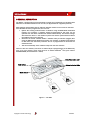
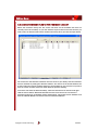
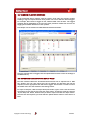
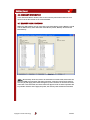
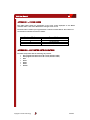
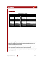
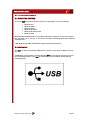
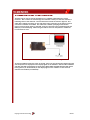
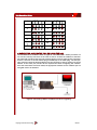
DA3
USER
MANUAL
INTELLIGENCE IN VALIDATION
Copyright Innovative Technology
GA339-4
DA3 User Manual
2
CONTENTS
1
2
3
4
5
6
6.1
6.2
6.3
6.4
6.5
6.6
6.7
6.8
7
7.1
7.2
7.3
7.4
7.5
7.6
7.7
7.8
7.9
Introduction
Power requirements
General description
Software installation
Connecting the DA3 to a PC
Programming the DA3
Adding datasets to the dataset library
Adding firmware to the firmware library
Storing files on the DA3
Tagging files for override
Importing and exporting set up files
Summary info
Memory card functions
VPS utilities
Using the DA3
Connecting a validator to the DA3
BNV match download
BNV override download
Set BNV to check mode
Serial comm. monitor
Collect note data
Copy A to DA3
Copy DA3 to A
Copy A to B
Appendix 1 – Error codes
Appendix 2 – Supported note validators
Copyright Innovative Technology
3
5
6
7
8
10
10
11
12
13
13
14
14
15
16
16
16
17
17
18
18
18
18
19
20
20
GA339-4
DA3 User Manual
3
1 INTRODUCTION
This manual describes the operation of the DA3 Validator Programming System,
programmed with firmware version VPS1001000000000 or later, using the VPS
software version 1.0.7 or later.
If you do not understand any part of this manual please contact the factory for
assistance, contact details are below. In this way we may continue to improve our
product.
This document is intended for those who will:
• Program the DA3
• Program validators using the DA3
Innovative Technology Ltd has a policy of continual product improvement. As a result
the products supplied may vary from the specification described here.
The ITL Logo is an international registered trademark and is the property of Innovative
Technology Limited.
Innovative Technology has a number of European and International Patents and
Patents Pending protecting this product. If you require further details please contact
the factory.
Innovative Technology is not responsible for any loss, harm, or damage caused by the
installation and use of this product. This does not affect your local statutory rights. If
in doubt please contact Innovative Technology for details of any changes
Kit Components
The DA3 Kit comprises of the following:
• DA3 Programming Unit
• USB A to USB B cable
• DA3 to ITL Note Validator Cable
• Support CD
.
MAIN HEADQUARTERS
Copyright Innovative Technology
Innovative Technology Ltd
Derker Street – Oldham – England - OL1 4EQ
Tel: +44 161 626 9999 Fax: +44 161 620 2090
E-mail: [email protected]
Web site: www.innovative-technology.co.uk
GA339-4
DA3 User Manual
GROUP
4
EMAIL CONTACT
BRAZIL
[email protected]
CHINA
[email protected]
COLUMBIA
[email protected]
GERMANY
[email protected]
UNITED KINGDOM
[email protected]
SPAIN
[email protected]
UNITED STATES OF AMERICA
[email protected]
REST OF THE WORLD
[email protected]
Copyright Innovative Technology
GA339-4
DA3 User Manual
5
5
2 POWER REQUIREMENTS
When programming the DA3 using the VPS software, power is taken from the USB bus;
no external power supply is required.
When programming validators, or using the DA3 card copy functions, power must be
applied via the host machine or from a separate 12V DC, 1500mA power supply.
Copyright Innovative Technology
GA339-4
DA3 User Manual
6
3 GENERAL DESCRIPTION
The DA3 is a programming system designed to enable the programming of ITL Bank Note
Validators in the field without the use of a PC (see Appendix 2 for supported products).
Many dataset and firmware files for different validator models can be stored on the DA3.
Once the DA3 has been programmed, the user can:
• Update the existing software within a validator using the BNV Match Download
Function. For example, a validator already programmed for UK notes can be
updated with the latest available UK dataset automatically. All custom settings
will remain the same i.e. the number of pulses set and the special interface within
the validator will not be changed
• Overwrite the stored software within a validator with pre-selected (tagged) files
using the BNV Override Download Function. For example, a validator programmed
for UK notes with the Binary interface can be re-programmed for Euro with the
ccTalk interface.
• Test the functionality of the validator away from the host machine.
There are also two memory card slots to enable simple reprogramming of the DA3 away
from a PC. The memory cards used must be an Atmel Dataflash® card, part number
AT45DCB008D (ITL Part Number - IC237)
Data Connection LED
RUN Button
Mode Indicator LEDs
Mode Select
Data
Card B
Data
Card A
Figure 1 – The DA3
Copyright Innovative Technology
GA339-4
4 SOFTWARE INSTALLATION
DA3 User Manual
7
NOTE: - To install the software you will need administrator rights to your PC.
Insert the Support CD into your computers CD Drive. The menu should appear
automatically.
Double click ‘Install VPS Software’
from the menu
The Welcome to the VPS Setup
Wizard will start
Click ‘Next’
The Select Installation Folder
screen will be displayed.
Select the path where you wish to
install the software (C:\Program
Files\VPS\ is the default path)
Click ‘Next’
A Confirm Installation screen will
be displayed.
Click ‘Next’
When the installation is complete
you will see this screen.
Click ‘Close’
Copyright Innovative Technology
GA339-4
DA3 User Manual
8
5 CONNECTING THE DA3 TO A PC
USB
Connection
NOTE: - To install the drivers for the DA3, you will need administrator rights to your PC.
Connect the DA3 to your PC via the supplied USB cable. (There is no need for a
separate power supply when programming the DA3 from your computer). When the
DA3 is only connected through the USB, the functions described in Chapter 7 are not
available.
Copyright Innovative Technology
GA339-4
DA3 User Manual
9
The Windows ‘Found New Hardware Wizard’
will be displayed.
Select ‘No, not this time’
Click ‘Next’
The wizard will then ask how you want to
proceed.
Select ‘Install from a list or specific location
(Advanced)’
Click ‘Next’
The Search and installation options screen
will be displayed. Select ‘Include this
location in the search’. Click ‘browse’ and
locate the driver files. The driver files are
stored within the installation directory of
the VPS software which is ‘C:\Program
files\VPS\ITL VPS USB Driver’ by default.
Click ‘Next’
A warning will be displayed informing you
that the driver has not passed Windows
Logo testing.
Click ‘Continue Anyway’
Windows will then install the
necessary software
When the software has been installed you
will see this screen.
Click ‘Finish’
A ‘Found New Hardware’ message will be
displayed when the installation is complete.
This message will close automatically.
Copyright Innovative Technology
GA339-4
DA3 User Manual
10
6 PROGRAMMING THE DA3
To use the DA3 you must first save the required datasets and firmware files to the DA3’s
internal memory. You can do this by either using the VPS Software (this chapter) or
copying data from a pre-programmed memory card (see Chapter 7.7).
To use the VPS software, you must select the files you wish to store on the DA3 from the
dataset library and the firmware library. When first used the libraries will be empty, you
will need to add files as detailed below. You will also need to add new files when reprogramming the DA3 with updated datasets or firmware.
6.1 ADDING DATASETS TO THE DATASET LIBRARY
Select the Dataset Library tab. The screen will show all the dataset files that are currently
stored in the library on your PC.
Click the Import button and locate the files you wish to add, the datasets will be added to
the library when you click the Open button
The screen lists the currencies that are stored in your library with the note denominations,
number of pulses and the dataset code. The revision code of the dataset is listed under
the relevant product heading. If the dataset for any product is not present then the version
number will not be listed under the product heading.
To remove a file from the dataset library, select the dataset to be removed and right click
the mouse. Select ‘Removed Selected Datasets’ from the menu to remove the dataset for
all validator models. Alternatively, select ‘Remove For Validator’ and then the validator
model to remove the file for individual validators.
Copyright Innovative Technology
GA339-4
DA3 User Manual
11
6.2 ADDING FIRMWARE FILES TO THE FIRMWARE LIBRARY
Select the Firmware Library tab. The screen will show all the firmware files that are
currently stored in the library on your PC. Click the Import button and locate the files you
wish to add, the firmware files will be added to the library when you click the Open button.
The screen lists the firmware interfaces that are stored in your library with the interfaces
that are available by setting the validator switches. The version of the stored firmware file
is listed under the relevant product heading. If the firmware for any product is not present
then the version number will not be listed under the product heading.
To remove a file from the firmware library, select the interface to be removed and right
click the mouse. Select ‘Removed Selected Firmware’ from the menu to remove the
firmware interface for all validator models. Alternatively, select ‘Remove For Validator’ and
then the validator Model to remove the file for individual validators
Copyright Innovative Technology
GA339-4
DA3 User Manual
12
6.3 STORING FILES ON THE DA3
In the dataset and firmware libraries, select the files you wish to save to the DA3.
Holding the Shift or Ctrl keys while clicking the mouse can make multiple selections.
Right click the mouse and a menu will appear. Select ‘Add Selected To Device’ to add
the file to the Connected Device window ready for download to the DA3.
On the Connected Device screen, files not yet downloaded to the DA3 will be listed in
grey. At this point you can select which files to tag to be used for the BNV Override
Download function (see Chapter 6.4). Click on the ‘Update Device’ button to save the
listed files to the DA3 memory.
To remove a file from the DA3, select the files to be removed and right click the mouse.
Select ‘Removed Selected‘ from the menu to remove the files for all validator models, or
select ‘Remove For Validator’ and then the validator model to remove the file for
individual validators. Click on the ‘Update Device’ button to update the DA3 memory and
remove the files.
Copyright Innovative Technology
GA339-4
NV200 Operations Manual
DA3 User Manual
13
31
6.4 TAGGING FILES FOR OVERRIDE
In the Connected Device window, click the revision code under the relevant product
heading to tag the required dataset. Each product can have a different dataset tagged.
For example, NV7 could be tagged as UK, whereas NV8 could be Euro. The tagged
datasets will be highlighted as red text. The same procedure should then be used for
tagging the firmware interfaces for each product.
See Chapter 7.3 for details on the BNV Override Download function.
Once the required files are tagged, click the Update Device button to save the settings to
the DA3 memory.
6.5 IMPORTING AND EXPORTING SET UP FILES
The files contained within the Connected Device window can be exported into a .DA3
file. Another user can then import this file. All dataset and firmware files will be
imported, and the appropriate files will still be tagged. This function is useful to ensure
other DA3 users have the same files and settings stored.
To export a setup file, click the ‘Export Setup File’ button, type in a file name and select
the location to store the file, then click the ‘Save’ button. To import a setup file, click the
‘Import Setup File’ button, locate the file you wish to import and click the ‘Open’ button.
Once the files are imported, you must click the ‘Update Device’ button to save them to a
DA3.
DA3 User Manual
Copyright Innovative Technology
16
GA339-4
DA3 User Manual
14
6.6 SUMMARY INFORMATION
In the Connected Device window, click on the ‘Summary Information’ button to run a
report of all the files stored on the connected DA3.
6.7 MEMORY CARD FUNCTIONS
Within the VPS software you can copy files to and from Memory card A, Memory card B
and the DA3 memory. Also delete files from Memory card A, Memory card B and the
DA3 memory.
NOTE: - New memory cards may need to be formatted. To format cards, disconnect the
DA3 from USB, host connector and power connector. Insert the new card into memory
card slot [A] and apply power either through the power connector or the host connector.
If the card is not formatted, the centre button will light red and no further operation will
be possible. Remove and re-apply the power, the memory card will then be formatted
Copyright Innovative Technology
GA339-4
DA3 User Manual
15
6.8 VPS UTILITIES
Using the VPS Utilities screen, you can update the operational firmware of your DA3
Click the ‘…’ button to browse for the firmware file, and then click the ‘Update VPS
Firmware’. The DA3 operational firmware will be updated.
DO NOT disconnect the DA3 while the firmware upgrade is taking place. Doing so
could permanently damage the DA3.
DA3 User Manual
Copyright Innovative Technology
16
GA339-4
DA3 User Manual
16
7 USING THE DA3
7.1 CONNECTING A VALIDATOR TO THE DA3
Connect the validator to the DA3 via the supplied 16way ribbon cable. Power must be
applied to the DA3 via a separate 12V 1500mA DC power supply, or from the host
machine. The functions described in this chapter will not be available if the DA3 is
powered only by the USB cable.
Host Machine
Power Connection
Validator Connection
7.2 BNV MATCH DOWNLOAD
This mode will update the connected BNV with the latest version of dataset and
firmware currently programmed into the BNV. All custom settings (pulses, special
interface etc) will remain the same. Tagging files has no effect when the DA3 is used
in this mode. For this function to operate, the versions of firmware and dataset stored
within the DA3 memory must be later than that stored within the connected validator.
•
•
•
•
•
•
•
•
•
Set the BNV to SSP mode as described in the BNV product manual. Depending on
the BNV model, this will be either by setting the dipswitches as shown on the
product label, or by pressing a download reset button
Connect the BNV to the DA3 as described in chapter 7.1 and apply power either
from the host machine or from a separate 12V power supply.
Press the Mode Select button repeatedly until the blue BNV MATCH DOWNLOAD
LED is illuminated. The RUN button will pulse green to indicate that this function
is available.
Press the Centre RUN button.
The centre RUN button will change colour to pulsing blue, and the Mode Indicator
LEDs will rotate back and forth as communication is established and the current
BNV settings are determined. The DATA CONNECTION LED with flicker as data is
transferred to and from the DA3. If there are no matching firmware or dataset
files stored on the DA3, the centre RUN button will change colour to pulsing red,
and the blue BNV MATCH DOWNLOAD LED will flash a code as described in
Appendix 1.
If all the files are available on the DA3, the Mode Indicator LED’s will rotate in an
anti-clockwise direction while the firmware is updated
Once the firmware update is complete, the Mode Indicator LED’s will rotate in a
clockwise direction as the dataset is updated.
When the firmware and dataset are successfully updated, the centre RUN button
will change to a pulsing green light and the BNV will reset.
If necessary, reset the BNV dipswitches to their original positions before reconnecting the BNV to the host machine.
Copyright Innovative Technology
GA339-4
DA3 User Manual
17
7.3 BNV OVERRIDE DOWNLOAD
This mode will overwrite the BNV with pre-selected (Tagged) firmware and dataset
files. For this function to operate, the DA3 must have dataset and firmware files
tagged for the attached BNV model. See Chapter 6.4 for details on tagging files.
•
•
•
•
•
•
•
•
•
Set the BNV to SSP mode as described in the BNV product manual. Depending on
the BNV model, this will be either by setting the dipswitches as shown on the
product label, or by pressing a download reset button.
Connect the BNV to the DA3 as described in chapter 7.1, and apply power either
from the host machine or from a separate 12V power supply.
Press the Mode Select button repeatedly until the blue BNV OVERRIDE
DOWNLOAD LED is illuminated. The RUN button will pulse green to indicate that
this function is available.
Press the Centre RUN button.
The centre RUN button will change colour to pulsing blue, and the Mode Indicator
LEDs will rotate back and forth as communication is established. The DATA
CONNECTION LED with flicker as data is transferred to and from the DA3. If there
are no files tagged for the connected BNV, the centre RUN button will change
colour to pulsing red, and the blue BNV OVERRIDE DOWNLOAD LED will flash a
code as described in Appendix 1.
The Mode Indicator LED’s will rotate in an anti-clockwise direction while the
firmware is updated
Once the firmware update is complete, the Mode Indicator LED’s will rotate in a
clockwise direction as the dataset is updated.
When the firmware and dataset are successfully updated, the centre RUN button
will change to a pulsing green light and the BNV will reset.
If necessary, set the BNV dipswitches to their required positions before reconnecting the BNV to the host machine.
7.4 SET BNV TO CHECK MODE
This function enables the validator to accept notes so that testing can take place
outside of the host machine.
•
•
•
•
•
•
Set the BNV to SSP mode as described in the BNV product manual. Depending on
the BNV model, this will be either by setting the dipswitches as shown on the
product label, or by pressing a download reset button.
Connect the BNV to the DA3 as described in chapter 7.1, and apply power either
from the host machine or from a separate 12V power supply.
Press the Mode Select button repeatedly until the blue SET BNV TO CHECK MODE
LED is illuminated. The RUN button will pulse green to indicate that this function
is available.
Press the Centre RUN button.
The centre RUN button will change colour to pulsing blue, and the DATA
CONNECTION LED with flash as data is transferred to and from the DA3. If
communications can not be established the centre RUN button will change colour
to pulsing red, and the blue SET BNV TO CHECK MODE LED will flash a code as
described in Appendix 1.
When notes are inserted and accepted, the Mode Indicator LED will switch off a
number of times according to which channel the note has been credited. For
example, if a note from channel 3 has been inserted, the Mode Indicator LED will
switch off and back on again 3 times
Copyright Innovative Technology
GA339-4
DA3 User Manual
18
7.5 SERIAL COMM MONITOR
This function is not yet implemented. The centre RUN button will not illuminate to
indicate that this function is not available.
7.6 COLLECT NOTE DATA
This function is not yet implemented. The centre RUN button will not illuminate to
indicate that this function is not available.
7.7 COPY A TO DA3
This function copies the contents of the memory card in slot A to the internal memory
of the DA3. All files stored in the DA3 memory will be overwritten. Note that new
memory cards may need formatting, see chapter 6.7 for more details.
•
•
•
•
•
Press the MODE SELECT button until the COPY [A]
DA3 LED is illuminated
Press the RUN button – the RUN button will change colour from pulsing green to
solid blue, and the MODE SELECT button light will switch off.
Press the RUN button again within 3 seconds to confirm.
If the RUN button is not pressed a second time within 3 seconds, the colour of
the button will revert to green, and the MODE SELECT button will re-light blue.
If there is no memory card in slot A, or the memory card is blank, the centre
RUN button will pulse red, and the blue COPY [A]
DA3 LED will flash a code
as described in Appendix 1.
The Mode Indicator LED’s will rotate in an anti-clockwise direction while the entire
contents of the memory card in slot A are be copied to the internal memory of the
DA3. All files stored in the DA3 memory will be overwritten.
When the copy is complete, the centre RUN button will pulse green.
7.8 COPY DA3 TO A
This function copies the contents of the internal memory of the DA3 to the memory
card in slot A. All files stored on the memory card will be overwritten. Note that new
memory cards may need formatting, see chapter 6.7 for more details.
•
•
•
•
•
Press the MODE SELECT button until the COPY DA3
[A] LED is illuminated
Press the RUN button – the RUN button will change colour from pulsing green to
solid blue, and the MODE SELECT button light will switch off.
Press the RUN button again within 3 seconds to confirm.
If the RUN button is not pressed a second time within 3 seconds, the
colour of the button will revert to green, and the MODE SELECT button will
re-light blue.
If there is no memory card in slot A the centre RUN button will pulse red,
and the blue DA3
[A] LED will flash a code as described in Appendix 1.
The Mode Indicator LED’s will rotate in an anti-clockwise direction while the entire
contents of the DA3 are copied to the memory card in slot A. All files stored on
the memory card will be overwritten.
When the copy is complete, the centre RUN button will pulse green.
Copyright Innovative Technology
GA339-4
DA3 User Manual
19
7.9 COPY A TO B
This function copies the contents of the memory card in slot A to the memory card in
slot B. All files stored on the memory card in slot B will be overwritten. Note that new
memory cards may need formatting, see chapter 6.7 for more details.
•
•
•
•
•
Press the MODE SELECT button until the COPY [A]
[B] LED is illuminated
Press the RUN button – the RUN button will change colour from pulsing green to
solid blue, and the MODE SELECT button light will switch off.
Press the RUN button again within 3 seconds to confirm.
If the RUN button is not pressed a second time within 3 seconds, the
colour of the button will revert to green, and the MODE SELECT button will
re-light blue.
If there is no memory card in slot [A] or [B], or the memory card in slot [A]
is blank, the centre RUN button will pulse red, and the blue COPY [A]
[B] LED will flash a code as described in Appendix 1.
The Mode Indicator LED’s will rotate in an anti-clockwise direction while the entire
contents of the memory card in slot [A] are copied to the memory card in slot B.
All files stored on the memory card in slot [B] will be overwritten.
When the copy is complete, the centre RUN button will pulse green.
DA3 User Manual
Copyright Innovative Technology
15
GA339-4
DA3 User Manual
20
APPENDIX 1 – ERROR CODES
The table below shows an explanation of the error codes displayed on the Mode
Indicator LED’s if the centre RUN button changes colour to red.
The flash code is shown by a long flash then a number of short flashes. The number of
short flashes indicates the cause of failure.
Number of flashes
2
3
4
5
Cause of failure
No validator connection found
No valid download files found
Download fail
Memory card fail
APPENDIX 2 – SUPPORTED NOTE VALIDATORS
The DA3 will operate with the following ITL products
• NV7 programmed firmware 1.09 or later (October 2003)
• NV8 programmed firmware 1.09 or later (October 2003)
• NV9
• NV10
• BV20
• BV50
• BV100
Copyright Innovative Technology
GA339-4
DA3 User Manual
21
REVISION HISTORY
STORY
TITLE:
Drawing No:
Author
Format
INNOVATIVE TECHNOLGY LTD
DA3 USER MANUAL
GA339
Project
RJS
Date
04/01/2007
MS WORD 2000
Issue
Issue A
Issue B
Release Date
04/01/2007
22/01/2007
Modified By
RJS
RJS
Issue C
08/02/2007
RJS
Issue 1
Issue 2
Issue 3
Issue 4
13/02/2007
20/02/2007
19/03/2007
17/11/2008
RJS
RJS
RJS
RJS
Comments
First draft
Second draft - reorganised
chapters
Third draft - addition of
memory card formatting
Initial release
Updated Appendix 2
Updated Appendix 2
Updated Appendix 2
Innovative Technology has a number of European and International Patents and Patents
Pending protecting this product. If you require further details please contact the factory.
Smiley® and the ITL Logo are international registered trademarks and they are the
property of Innovative Technology Limited.
Innovative Technology is not responsible for any loss, harm, or damage caused by the
installation and use of this product. This does not affect your local statutory rights. If in
doubt please contact Innovative Technology for details of any changes.
In line with continued product development Innovative Technology Ltd. reserves the right
to change specifications without prior notice. The data used in this document may be
used as a guideline only.
Copyright Innovative Technology
GA339-4
DA2
INSTALLATION
GUIDE
INTELLIGENCE IN VALIDATION
Copyright Innovative Technology
GA338-2
DA2 Installation Guide
2
CONTENTS
1
2
3
4
5
6
DA2 kit contents
System requirements
Windows installation
Verifying installation and identifying the DA2 com port
Installing additional DA2s
Uninstalling the DA2
Copyright Innovative Technology
3
5
6
11
11
12
GA338-2
DA2 Installation Guide
3
1 DA2 KIT CONTENTS
You will have received the following items in your DA2 kit.
•
•
•
•
•
DA2
USB type-A to type-B cable
DA2 to NV7/8/9/10 cable
Power cable
ITL Support CD-ROM
If any of these items are missing please contact Innovative Technology Ltd to arrange
for replacement.
If you do not understand any part of this guide please contact the factory for
assistance, contact details are below. In this way we may continue to improve our
product.
Innovative Technology Ltd has a policy of continual product improvement. As a result
the products supplied may vary from the specification described here.
The ITL Logo is an international registered trademark and is the property of Innovative
Technology Limited.
Innovative Technology has a number of European and International Patents and
Patents Pending protecting this product. If you require further details please contact
the factory.
Innovative Technology is not responsible for any loss, harm, or damage caused by the
installation and use of this product. This does not affect your local statutory rights. If
in doubt please contact Innovative Technology for details of any changes
MAIN HEADQUARTERS
Copyright Innovative Technology
Innovative Technology Ltd
Derker Street – Oldham – England - OL1 4EQ
Tel: +44 161 626 9999 Fax: +44 161 620 2090
E-mail: [email protected]
Web site: www.innovative-technology.co.uk
GA338-2
DA2 Installation Guide
GROUP
4
EMAIL CONTACT
BRAZIL
[email protected]
CHINA
[email protected]
COLOMBIA
[email protected]
GERMANY
[email protected]
ENGLAND
[email protected]
SPAIN
[email protected]
UNITED STATES OF AMERICA
[email protected]
REST OF THE WORLD
[email protected]
Copyright Innovative Technology
GA338-2
DA2 Installation Guide
5
5
2 SYSTEM REQUIREMENTS
2.1 OPERATING SYSTEMS
To use the DA2 kit you must ensure that your PC’s operating is one of the following
•
•
•
•
•
•
Windows 98 *
Windows 98SE *
Windows 2000 *
Windows XP Home
Windows XP Professional
Windows Vista
Windows 95 and Windows NT do not support USB devices. However you can use a DA1 kit –
this will allow you to use any of the current Innovative Technology Bank Note Validator
download tools.
* NB: Windows 98, 98SE and 2000 are unsupported operating systems
2.2 HARDWARE
The DA2 is a Universal Serial Bus (USB) device. It must be connected to a USB port on your
PC.
A USB type-A to type-B cable is included with the DA2. The type-A plug connects to your PC.
The type-B plug connects to the DA2. The USB ports on your PC will be marked with the
following symbol.
Copyright Innovative Technology
GA338-2
DA2 Installation Guide
6
3 WINDOWS INSTALLATION
To install a DA2 you do not need to connect a Bank Note Validator or a power supply.
Simply connect the DA2 to the PC with the included USB cable.
3.1 WINDOWS 98/WINDOWS 98SE
Before connecting your DA2 insert the ITL support
CD-ROM into your PC.
Once you have connected your DA2
the Add New Hardware Wizard will start and the
following screen will be displayed.
Click on Next >
The following screen allows you to select a
method for finding the driver for the DA2.
Make sure that “Search for the best driver
for your device” is selected.
Click on Next >
Make sure that “specify a location” is checked.
In the location box type “[Drive]:\drivers” where
[Drive] represents your CD-ROM drive letter
(usually D).
Click on Next >
The Add New Hardware Wizard will show
that the ITL USB (high speed) Serial
Controller has been found.
Click on Next > to load the driver
The following screen will be displayed
when the driver is loaded.
Click on Finish
Your DA2 is ready for use.
Copyright Innovative Technology
GA338-2
3.2 WINDOWS 2000
DA2 Installation Guide
7
Before connecting your DA2 insert the DA2 CD-ROM
into your PC. Once you have connected your DA2
a window open showing your PC has found a new device.
When the Add New Hardware Wizard starts the
following screen will be displayed.
Click on Next >
Make sure that Search for a suitable driver for my
device is checked.
Click on Next >
On the following screen make sure that Specify
a location is checked.
Click on Next >
A browser window will open to allow you to select the
driver’s location. In the location box type
“[Drive]:\drivers” where [Drive] represents your
CD-ROM drive letter (usually D).
Click on Next >
A box will be displayed indicating that the
driver has been found.
Click on Next >
Copyright Innovative Technology
GA338-2
DA2 Installation Guide
8
When the driver has been successfully
installed, the following screen will be shown.
Click on Finish
A second New Hardware Wizard will open.
Click on Next >
Make sure that Search for a suitable
driver for my device is checked.
Click on Next >
A browser window will open to allow you to select
the driver’s location. In the location box type
“[Drive]:\drivers” where [Drive] represents your
CD-ROM drive letter (usually D).
Click on Next >
A box will be displayed indicating that the driver
has been found.
Click on Next >
When the driver has been successfully installed,
the following screen will be shown.
Click on Finish
Copyright Innovative Technology
GA338-2
DA2 Installation Guide
9
3.3 WINDOWS XP (HOME AND PROFESSIONAL)
Before connecting your DA2 insert the DA2 CD-ROM
into your PC. Once you have connected your DA2 a
message bubble will appear informing you that a
new device has been connected.
After a few moments the Add New Hardware Wizard
will start and the following screen will be displayed.
Make sure that Install the software automatically
is checked.
Click on Next >
The following screen will be displayed while the
Wizard searches for the driver. If you have already
inserted the DA2 CD-ROM Windows XP will
automatically find the driver.
When the driver has been found a message
will be displayed informing you that the driver
has not passed Windows Logo testing.
Click on Continue Anyway
When the driver has successfully loaded you will
see the following screen.
Click Finish
A second Found New Hardware Wizard will now
open. Make sure that Install the software automatically
is checked.
Click on Next >
.
Copyright Innovative Technology
GA338-2
DA2 Installation Guide
10
The search window will again be displayed
When the driver has been found a message
will be displayed informing you that the driver
has not passed Windows Logo testing.
Click on Continue Anyway
When the driver has successfully loaded you
will see the following screen.
Click Finish
Your DA2 is now ready for use.
Copyright Innovative Technology
GA338-2
DA2 Installation Guide
11
4 VERIFYING INSTALLATION AND IDENTIFYING THE DA2 COM PORT
4.1 WINDOWS 98/98SE/ME
1. Right Click on the My Computer icon, then
select Properties.
2. Click on the Device Manager tab.
3. Locate the Port (Com & LPT) icon and click
on the + sign next to it.
4. You should see a list of your PC’s RS232,
LPT (Parallel) and the DA2 port (which will be
labelled as ITL USB Serial Port (Com λ) where
λ indicates the Com Port number the DA2 had
been installed to).
4.2 WINDOWS 2000
1. Right click on the My Computer icon, and
then select Properties.
2. Click on the Hardware tab then the Device
Manager button.
3. Locate the Port (Com & LPT) icon and click
on the + sign next to it.
4. You should see a list of your PC’s RS232,
LPT (Parallel) and the DA2 port (which will be
labelled as ITL USB Serial Port (Com λ) where
λ indicates the Com Port number the DA2 had
been installed to).
4.3 WINDOWS XP (HOME AND PROFESSIONAL)
1. Right click on the My Computer icon, and
then select Properties.
2. Click on the Hardware tab then the Device
Manager button.
3. Locate the Port (Com & LPT) icon and click
on the + sign next to it.
4. You should see a list of your PC’s RS232,
LPT (Parallel) and the DA2 port (which will be
labelled as ITL USB Serial Port (Com λ) where
λ indicates the Com Port number the DA2
had been installed to).
5 INSTALLING ADDITIONAL DA2S
To install additional DA2s follow the instructions for installation for your Operating
System. You will not need to insert the DA2 CD-ROM for additional DA2s if you are using
Windows XP (Home or Professional).
Copyright Innovative Technology
GA338-2
DA2 Installation Guide
12
6 UNINSTALLING THE DA2
6.1 WINDOWS 98/98SE/ME
1. Right Click on the My Computer icon, then
select Properties.
2. Click on the Device Manager tab.
3. Locate the Port (Com & LPT) icon and click
on the + sign next to it.
4. You should see a list of your PC’s RS232,
LPT (Parallel) and the DA2 port (which will be
labeled as ITL USB Serial Port (Com λ) where λ
indicates the Com Port number the DA2 had
been installed to).
5. Click on the DA2 (it should now be highlighted).
6. Click on the REMOVE button.
Follow the on screen instructions.
6.2 WINDOWS 2000
1. Right click on the My Computer icon, and
then select Properties.
2. Click on the Hardware tab then the Device
Manager button.
3. Locate the Port (Com & LPT) icon and click
on the + sign next to it.
4. You should see a list of your PC’s RS232,
LPT (Parallel) and the DA2 port (which will be
labeled as ITL USB Serial Port (Com λ) where λ
indicates the Com Port number the DA2 had
been installed to).
5. Click on the DA2 (it should now be highlighted).
6. Right click on the DA2 and select uninstall.
Follow the on screen instructions.
6.3 WINDOWS XP (HOME AND PROFESSIONAL)
1.Right click on the My Computer icon, and
then select Properties.
2. Click on the Hardware tab then the Device
Manager button.
3. Locate the Port (Com & LPT) icon and click
on the + sign next to it.
4. You should see a list of your PC’s RS232,
LPT (Parallel) and the DA2 port (which will be
labeled as ITL USB Serial Port (Com λ) where λ
indicates the Com Port number the DA2 had
been installed to).
5. Right click on the DA2 and select uninstall.
Follow the on screen instructions.
Copyright Innovative Technology
GA338-2
DA2 Installation Guide
13
REVISION HISTORY
TITLE:
Drawing No:
Author
Format
INNOVATIVE TECHNOLGY LTD
DA2 INSTALLATION GUIDE
GA338
Project
MH
Date
10/12/2003
MS WORD 2000
Issue
Issue 1
Release Date
10/12/2003
Modified By
MH
Issue 2
03/01/2007
RJS
Comments
Pre-release development
issue
First Release
Innovative Technology has a number of European and International Patents and Patents
Pending protecting this product. If you require further details please contact the factory.
Smiley® and the ITL Logo are international registered trademarks and they are the
property of Innovative Technology Limited.
Innovative Technology is not responsible for any loss, harm, or damage caused by the
installation and use of this product. This does not affect your local statutory rights. If in
doubt please contact Innovative Technology for details of any changes.
In line with continued product development Innovative Technology Ltd. reserves the right
to change specifications without prior notice. The data used in this document may be
used as a guideline only.
Copyright Innovative Technology
GA338-2
DA1 KIT
QUICK START
GUIDE
INTELLIGENCE IN VALIDATION
Copyright Innovative Technology
GA151
DA1 Quick Start Guide
2
CONTENTS
1
2
3
4
5
Introduction
Kit components
Connecting the DA1 to test a validator
Connecting a validator to a PC using a DA1
Software installation
Copyright Innovative Technology
3
3
5
6
7
GA151
DA2 Quick Start Guide
3
1 INTRODUCTION
The DA1 Kit is designed to be used for the following:
• Connection of any ITL note validator to a PC, to allow note data and firmware to be
upgraded.
• Allow testing of a NV2, NV3, NV4, NV4X or NV5 note validators independently of the
host machine.
2. KIT COMPONENTS
The DA1 Kit comprises of the following components:
1. DA1 adapter board.
2. Adapter to Validator cable (for NV2, NV3, NV4, NV4X and NV5).
3. Power Cable.
4. Quick Start Guide.
5. ITL Support CD-ROM (optional).
Please check that you have received all the parts. If any of these items are missing please
contact Innovative Technology Ltd to arrange for replacement.
If you do not understand any part of this guide please contact the factory for
assistance, contact details are below. In this way we may continue to improve our
product.
Innovative Technology Ltd has a policy of continual product improvement. As a result
the products supplied may vary from the specification described here.
The ITL Logo is an international registered trademark and is the property of Innovative
Technology Limited.
Innovative Technology has a number of European and International Patents and
Patents Pending protecting this product. If you require further details please contact
the factory.
Innovative Technology is not responsible for any loss, harm, or damage caused by the
installation and use of this product. This does not affect your local statutory rights. If
in doubt please contact Innovative Technology for details of any changes
MAIN HEADQUARTERS
Copyright Innovative Technology
Innovative Technology Ltd
Derker Street – Oldham – England - OL1 4EQ
Tel: +44 161 626 9999 Fax: +44 161 620 2090
E-mail: [email protected]
Web site: www.innovative-technology.co.uk
GA151
DA1 Quick Start Guide
GROUP
4
EMAIL CONTACT
BRAZIL
[email protected]
CHINA
[email protected]
COLUMBIA
[email protected]
GERMANY
[email protected]
ENGLAND
[email protected]
SPAIN
[email protected]
UNITED STATES OF AMERICA
[email protected]
REST OF THE WORLD
[email protected]
Copyright Innovative Technology
GA151
DA1 Quick Start Guide
5
5
3 CONNECTING THE DA1 TO TEST A VALIDATOR.
The DA1 can be used to test the acceptance of a validator independently of a host
machine. This is useful for determining if the validator is faulty or if the host machine is
inhibiting some of the channels. The connections are made as shown in figure 1. The
cable with a 15-way connector on one end and a 5-way connector on the other is used to
connect the validator to the DA1. The cable with a 3.5mm jack plug and 2 banana
plugs is used to supply power to the DA1. Connect +12 volts to the red banana plug and
GND (0V) to the black plug. When using the DA1 to test note acceptance it should not
be connected to a PC.
Figure 1 - Connecting a DA1 to a validator for testing
To test the validator insert the notes as normal, if the note is accepted the channel the note
was accepted on is displayed on the display lights on the validator. NV2 and NV3 validators
will flash the LED corresponding to the channel. NV4, NV4X and NV5 validators will flash a
binary pattern (as shown below) on the display lights on the validator. In this mode all
channels are enabled (not inhibited).
Copyright Innovative Technology
GA151
DA1 Quick Start Guide
Number
6
1
LED Display
2 3
4
1
Number
Led Display
2
3 4
8
2
9
3
10
4
11
5
12
6
7
1
13
14
4 CONNECTING A VALIDATOR TO A PC USING THE DA1.
The connections are made as shown in figure 2. The cable with a 15-way connector on
one end and a 5-way connector on the other is used to connect the validator to the DA1.
The cable with a 3.5mm jack plug and 2 banana plugs is used to supply power to the DA1.
Connect +12 volts to the red banana plug and GND (0V) to the black plug. The 9-way Dtype connector should be plugged directly into the serial port of the PC, taking note of the
number of the serial port, as this will be required later when configuring the software.
Once the connections have been made, the appropriate software for the validator you are
using will need to be installed.
Figure 2 - Connecting a DA1 to a validator and PC for upgrading.
Copyright Innovative Technology
GA151
DA1 Quick Start Guide
7
5 SOFTWARE INSTALLATION
To install the software required to upgrade datasets and firmware, insert the optional
CDROM into the CDROM drive. An installation menu will appear, select the product that
you wish to download, and then select the software you wish to use. Follow the
onscreen instruction to complete the installation. Instructions for configuring and using
the software you have installed can by found in the online help for that software.
8
Copyright Innovative Technology
GA151
DA1 Quick Start Guide
8
REVISION HISTORY
TITLE:
Drawing No:
Author
Format
INNOVATIVE TECHNOLGY LTD
DA1 QUICK START GUIDE
GA151
Project
PD
Date
17/08/2000
MS WORD 2000
Issue
Issue 1
Release Date
17/08/2000
Modified By
PD
Comments
Production release
Innovative Technology has a number of European and International Patents and Patents
Pending protecting this product. If you require further details please contact the factory.
Smiley® and the ITL Logo are international registered trademarks and they are the
property of Innovative Technology Limited.
Innovative Technology is not responsible for any loss, harm, or damage caused by the
installation and use of this product. This does not affect your local statutory rights. If in
doubt please contact Innovative Technology for details of any changes.
In line with continued product development Innovative Technology Ltd. reserves the right
to change specifications without prior notice. The data used in this document may be
used as a guideline only.
Copyright Innovative Technology
GA151