1
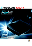
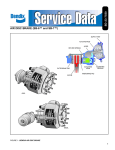
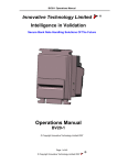
NV9 USB MANUAL SET INTRODUCTION NV9 USB Manual Set - Introduction 1 MANUAL AMENDMENTS Document Base Details Spec. Used GA550-1 GA138 GA959 Issue Date 29/02/11 01/11/10 29/03/11 Receipt Date 17/05/11 22/01/11 29/07/11 Comments Amendment Details Rev. -- Date 13/04/12 Amendment Details Revised First Issue Copyright © Innovative Technology Ltd 2013 Issued by EAM GA00550-2 NV9 USB Manual Set - Introduction 2 NV9 USB MANUAL SET - INTRODUCTION COPYRIGHT 3 LIMITED WARRANTY 3 PRODUCT SAFETY INFORMATION 3 INTRODUCTION 4 FEATURES 5 TYPICAL APPLICATIONS 5 STRUCTURE OF THIS MANUAL SET 6 WHICH SECTION IS RELEVANT TO ME? 6 MAIN HEADQUARTERS Innovative Technology Ltd Derker Street – Oldham – England - OL1 4EQ Tel: +44 161 626 9999 Fax: +44 161 620 2090 E-mail: [email protected] Web site: www.innovative-technology.co.uk BRAZIL [email protected] CHINA [email protected] GERMANY [email protected] SPAIN [email protected] UNITED KINGDOM [email protected] UNITED STATES OF AMERICA [email protected] REST OF THE WORLD [email protected] Copyright © Innovative Technology Ltd 2013 GA00550-2 NV9 USB Manual Set - Introduction 3 COPYRIGHT This manual set is Copyright © Innovative Technology Ltd., 2012. No part of this publication may be reproduced in any form or by any means or used to make any derivative such as translation, transformation, or adaptation without permission from Innovative Technology Ltd. The contents of this manual set may be subject to change without prior notice. LIMITED WARRANTY Innovative Technology Ltd warrants each of its hardware products to be free from defects in workmanship and materials under normal use and service for a period commencing on the date of purchase from Innovative Technology Ltd or its Authorized Reseller, and extending for the length of time stipulated by Innovative Technology Ltd. A list of Innovative Technology Ltd offices can be found in every section of this manual set. If the product proves defective within the applicable warranty period, Innovative Technology Ltd will repair or replace the product. Innovative Technology Ltd shall have the sole discretion whether to repair or replace, and any replacement product supplied may be new or reconditioned. The foregoing warranties and remedies are exclusive and are in lieu of all other warranties, expressed or implied, either in fact or by operation of law, statutory or otherwise, including warranties of merchantability and fitness for a particular purpose. Innovative Technology Ltd shall not be liable under this warranty if it’s testing and examination disclose that the alleged defect in the product does not exist or was caused by the customer's or any third person's misuse, neglect, improper installation or testing, unauthorized attempts to repair, or any other cause beyond the range of the intended use. In no event will Innovative Technology Ltd be liable for any damages, including loss of profits, cost of cover or other incidental, consequential or indirect damages arising out the installation, maintenance, use, performance, failure or interruption of a Innovative Technology Ltd product, however caused. PRODUCT SAFETY INFORMATION Throughout this manual set, we may draw your attention to key safety points that you should be aware of when using or maintaining the product. These safety points will be highlighted in a box, like this: Caution! Mains voltage is present on these terminals This manual set and the information it contains is only applicable to the model stated on the front cover, and must not be used with any other make or model. Copyright © Innovative Technology Ltd 2013 GA00550-2 NV9 USB Manual Set - Introduction 4 INTRODUCTION The NV9 USB validator is made up of three basic components: an NV9 USB validator head, removable bezel and a cashbox (as shown below): Removable bezel NV9 USB validator head Cashbox The NV9 USB validator is a device that can accept, validate and store 300 or 600 bank notes of mixed denominations. NV9 USB Rear View NV9 USB Side View NV9 USB Front View The NV9 USB Validator leaves the factory preset to at least one currency and one firmware interface so that it is ready for immediate installation. The NV9 USB validator works with any NV9 USB currency dataset created by Innovative Technology Ltd datasets can be downloaded from the Support section of the ITL website. Copyright © Innovative Technology Ltd 2013 GA00550-2 NV9 USB Manual Set - Introduction 5 FEATURES The NV9 USB validator has many innovative features, including: 300 or 600 note capacity cashboxes available Accepts up to 15 different note denominations (in serial control mode) Accepts, validates and stores multiple denominations of bank notes in less than 3 seconds Secure encrypted protocol available for communication TYPICAL APPLICATIONS The NV9 USB validator can be used in a variety of situations where high security and high volume bank note acceptance and validation are needed. Some typical applications are: AWP and SWP applications Self-Serve and Retail Kiosks Casinos Parking and Ticketing Vending Copyright © Innovative Technology Ltd 2013 GA00550-2 NV9 USB Manual Set - Introduction 6 STRUCTURE OF THIS MANUAL SET This manual set is made up of seven sections, each is supplied in a separate Portable Document Format (PDF) file, so you only need to download or print the section relevant to your requirements: Introduction Section 1 – Quick Start and Configuration Guide Section 2 – Field Service Manual Section 3 – ITL Software Support Guide Section 4 – Mechanical and Electrical Manual Section 5 – Software Implementation Guide Section 6 – Technical Appendices WHICH SECTION IS RELEVANT TO ME? Quick Start and Configuration Guide: – Most users should use this section; typical users are software engineers looking at how to make it work, project engineers evaluating their first unit, or installation engineers installing the unit into a host machine. – This section contains the essential information that a user needs to quickly assemble and configure the NV9 USB validator ready for installation into the host machine. Field Service Manual: – Typically used by a field service engineer who is maintaining the product. – This section contains the essential information that the field service engineer needs to clean, maintain and fault find an NV9 USB validator that is installed in a host machine. ITL Software Support Guide: – Any user who wants to test the functionality of the unit, reprogram the firmware or dataset, or set up the encryption key, address or routing for the unit. – This section contains the information needed for a user to configure and program the NV9 USB validator, using a range of software tools. Copyright © Innovative Technology Ltd 2013 GA00550-2 NV9 USB Manual Set - Introduction 7 Mechanical and Electrical Manual: – Design engineers who are designing a host machine cabinet, or looking to integrate the NV9 USB validator into an existing cabinet. – This section contains the all the mechanical and electrical information a designer needs to effectively integrate the NV9 USB validator into a host machine. Software Implementation Guide: – Software engineers looking at how to implement the NV9 USB validator in their host machine, or design engineers looking at including the unit in their host machine. – The information in this section details the communications protocols, specific commands and interfaces used including eSSP and ccTalk. Technical Appendices: – These appendices have no specific audience, but users can find relevant and useful information here. – This section includes information on product approvals, technical specifications and ordering information. Copyright © Innovative Technology Ltd 2013 GA00550-2 SECTION 1 NV9 USB MANUAL SET QUICK START AND CONFIGURATION GUIDE NV9 USB Manual Set – Section 1 2 NV9 USB MANUAL SET – SECTION 1 1. QUICK START AND CONFIGURATION GUIDE 3 1.1 Assembly 3 1.2 Bezel Removal and Refitting: 6 1.3 Interfacing 7 1.4 Configuration 8 1.5 Connector and Pinouts 9 1.6 Programming 10 1.7 Technical Specifications 11 1.8 NV9 USB Bezel Flash Codes 12 1.9 Fault Finding 13 1.10 Frequently Asked Questions 15 Copyright © Innovative Technology Ltd 2012 GA00550-2 NV9 USB Manual Set – Section 1 1. 3 QUICK START AND CONFIGURATION GUIDE This section is one part of a complete manual set: most users should use this section of the manual - typical users are software engineers looking at how to make it work, project engineers evaluating their first unit, or installation engineers installing the unit into a host machine. This section contains the essential information that a user needs to quickly assemble and configure the NV9 USB validator ready for installation into the host machine. Information Validator compatibility. 1.1 The NV9 USB validator is pin for pin compatible with the NV7 / NV8 / NV9 / NV10 series of validators, but NOT with earlier versions of the product (NV2 – NV5). Assembly Installing the NV9 USB is a simple operation; the validator can be installed vertically or horizontally, depending on the type of cashbox fitted or orientation needed: 1. If the validator is fitted with a clip-on cashbox, then the validator will be mounted VERTICALLY 2. The validator is secured in the host machine using a suitable vertical bezel Copyright © Innovative Technology Ltd 2012 GA00550-2 NV9 USB Manual Set – Section 1 3. The cashbox is attached to the validator by locating and sliding until the cashbox is clipped securely 4. If the validator is fitted with a slide-on cashbox, then the validator can be mounted HORIZONTALLY or VERTICALLY 5. The validator will be fitted with a suitable horizontal or vertical bezel Copyright © Innovative Technology Ltd 2012 4 GA00550-2 NV9 USB Manual Set – Section 1 6. The cashbox housing is mounted in the host machine with the NV9 USB mounted on top. The cashbox is then slid into the housing until it is securely clipped. 7. If the validator is fitted with an NV11 standard cashbox, then the validator will be mounted HORIZONTALLY 8. The validator will be fitted with a suitable horizontal bezel 9. The cashbox is attached to the validator by locating and sliding until the cashbox is clipped securely Copyright © Innovative Technology Ltd 2012 5 GA00550-2 NV9 USB Manual Set – Section 1 Information Check website for options. 6 There are many variants of bezel and cashbox type available for the NV9 USB validator. Please check the ITL website (www.innovative-technology.co.uk) for up to date information on the options available. The technical drawings which can be found at the end of this section show all the dimensional information needed to mount the unit. WARNING! Do not attempt disassembly 1.2 Do not attempt to disassemble the NV9 USB validator head – trying to do this could cause personal injury and will damage the unit beyond repair. Bezel Removal and Refitting: The bezel is removed by pushing the red locking arms on both sides of the validator upwards, and sliding the bezel away from the locking arms b. Slide bezel away from locking arms a. Push locking arms upwards Lift the bezel off once the bezel has been slid fully across and is clear of the locating pins Lift upwards to remove Locating pins Copyright © Innovative Technology Ltd 2012 GA00550-2 NV9 USB Manual Set – Section 1 7 The bezel is refitted by pushing the bezel back onto the locating pins and sliding backwards until all six pins are engaged in the slots. The locking arms will then spring back and locate into the bezel. Caution! Check locking arms. 1.3 Always make sure that BOTH locking arms are fully located in the bezel – trying to operate the validator if they are not correctly located can cause unit damage. Interfacing The connector needed to set up and interface the NV9 USB Validator is easily accessible on the side of the unit: Interface Socket Copyright © Innovative Technology Ltd 2012 GA00550-2 NV9 USB Manual Set – Section 1 1.4 8 Configuration The NV9 USB does not use DIP switches to configure the unit – configuration and setting is carried out by using a Configuration Button mounted on top of the unit: Configuration Button There are several functions available when using the Configuration Button, and these are listed in the next table: WARNING! Risk of unit damage When in programming mode, do not turn off the power before the operation is complete as this will make the unit unusable. Copyright © Innovative Technology Ltd 2012 GA00550-2 NV9 USB Manual Set – Section 1 9 Action Press and hold (more than 2 seconds) until the bezel illuminates, then release Press once (less than 1 second) Power Status Function Powered ON Sets validator to Programming mode (SSP) Press twice (within half a second) Press and hold as validator is powered up Powered ON Flash Count 1 2 3 6 7 8 1.5 Interface SSP Pulse MDB ccTalk SIO Parallel Powered ON Powered OFF / ON Enables Configuration Card programming – press again to cancel this mode Shows current interface type (see flash count table below) Resets to factory settings The NV9 USB Validator leaves the factory preset to at least one currency and one interface so that it is ready for immediate installation. The dataset and interface used are shown on the label fixed to the top of the validator head. Connector and Pinouts The NV9 USB Validator has a single connector that is used to allow interfacing and programming. Information Power always required regardless of connection type. Power is always required on pins 15 and 16 of the 16 way connector. The connector is a 16 pin socket used to interface the NV9 USB to the host machine. The pin numbering of the socket is shown below, as well as an overview of the socket connections: Pin 1 5 11 12 13 15 16 Copyright © Innovative Technology Ltd 2012 Description Serial Data Out (Tx) Serial Data In (Rx) USB Data + USB Data USB Power (+5V) +V 0V / Ground Connection GA00550-2 NV9 USB Manual Set – Section 1 10 To use a USB connection with the NV9 USB, a USB cable fitted with a 16 way connector on one end (ITL Part Number CN00392) should be used. The CN00392 cable fits into the 16 way connector and allows high speed programming and serial communications when used in SSP, ccTalk and SIO modes. When using the USB connection, power must be supplied to the NV9 USB using the CN00392 cable. 1.6 Programming Full details on programming the NV9 USB Validator can be found in Section 3 of this manual set (ITL Software Support Guide). Copyright © Innovative Technology Ltd 2012 GA00550-2 NV9 USB Manual Set – Section 1 1.7 11 Technical Specifications The full technical specifications for the NV9 USB Validator can be found in Section 6, Appendix B of this manual set. A brief summary is given here: DC Voltage Absolute limits Absolute limits (when fitted with IF5 interface) Supply ripple voltage Minimum 10.8 V 18 V Nominal 12 V --- 0V 0V Maximum 13.2 V 48 V DC or 34 V AC 0.25 V @ 100 Hz Supply Current Standby Running Peak (motor stall) 200 mA 1A 1.5 A Interface Logic Levels Logic Low Logic High Inputs Outputs (2.2 kΩ pull-up) 0 V to +0.5 V +0.6 V +3.7 V to +12 V Pull-up voltage of host interface 50 mA per output Maximum current sink WARNING! Use suitable power supply Ensure that the supply voltage to the NV9 USB is not lower than 10.8 V and that the power supply can provide sufficient current to avoid incorrect operation and excessive note rejects. We recommend that your power supply is capable of supplying 12V DC at 3 A. For 12V operation, use TDK Lambda model SWS50-12. This power supply is available from a variety of suppliers including Farnell (stock code 1184645) and RS (stock code 466-5869). Copyright © Innovative Technology Ltd 2012 GA00550-2 NV9 USB Manual Set – Section 1 1.8 12 NV9 USB Bezel Flash Codes The NV9 USB Validator has inbuilt fault detection facilities. If there is a configuration or other error the NV9 USB front bezel will flash in a particular sequence; a summary of the Bezel Flash Codes for the NV9 USB is shown below: Flashes Long Short 0 0 1 2 None Note path jam 3 Unit not initialised 1 Firmware checksum error Interface checksum error or unable to set programmed interface EEPROM checksum error Dataset checksum error Power supply too low Power supply too high 2 3 3 4 1 4 Indicated Error 2 Copyright © Innovative Technology Ltd 2012 Comments Remove obstruction and follow the cleaning procedure in Section 2 of this manual set Contact ITL technical support Download new firmware Check power supply GA00550-2 NV9 USB Manual Set – Section 1 1.9 13 Fault Finding Please use this flow chart with the Flash Codes in the previous sub-section as an aid to help resolve any configuration or start up problems you might have after installing the NV9 USB validator Incorrect currency file Check the required dataset is programmed using the Validator Manager Software (see Section 3 of this manual set). Notes not included in currency file Check the required note denomination and issue is included in the currency file using the Validator Manager Software (see Section 3 of this manual set). Notes inhibited by host machine Check the host machine is ready to accept notes and that the maximum allowed credit hasn’t been exceeded. If a coin hopper is fitted, make sure it isn’t empty. Bill path obstructed Check there is sufficient clearance for note ejection after acceptance (see Section 4 of this manual set). No power Check there is power to the validator, and that it is within the tolerances specified in the Technical Specification (see subsection 1.7 or Section 6 of this manual set). Incorrect interface programmed Check which interface the validator is programmed for by pressing the configuration button twice – the displayed code indicates which interface is programmed (see subsection 1.4 of this manual set). All notes rejected (bezel LEDs ON) Notes not accepted (bezel LEDs OFF) Power supply out of specification Check voltage and current supplied to the validator are within the tolerances specified in the Technical Specification (see subsections 1.7 or Section 6 of this manual set). Check there is sufficient clearance for note ejection after acceptance (see Section 4 of this manual set). Notes accepted but no credit given Rear note detect sensor obscured Copyright © Innovative Technology Ltd 2012 Check there are no foreign objects obstructing the sensors (see Section 2 of this manual set). Check the back security flap moves freely (this is the black plastic flap at the rear underside of the validator head) GA00550-2 NV9 USB Manual Set – Section 1 Foreign objects in note path Acceptor runs slowly or intermittently Incorrect supply voltage Unit damage Bezel LEDs are flashing Motor continues to run Various reasons Foreign object or note in the note path 14 Check and clean the note path (see Section 2 of this manual set). Check drive belts are fitted correctly and that there is no debris underneath the belts. Check voltage and current supplied to the validator are within the tolerances specified in the Technical Specification (see subsection 1.7 or Section 6 of this manual set). If possible, replace damaged components (see Section 4 of this manual set). IF YOU HAVE ANY DOUBTS, RETURN THE UNIT TO ITL FOR REPAIR Check the flash code tables for an understanding of the issue (see subsection 1.8 of this manual set). Check and clean the note path (see Section 2 of this manual set), then reset the validator. In some cases you may also need to reset the host machine. If you are unsure about the cause or how to resolve the problem, please contact ITL’s technical support department. Support contact details can be found on the ITL website (www.innovative-technology.co.uk), or on the last page of this section. Copyright © Innovative Technology Ltd 2012 GA00550-2 NV9 USB Manual Set – Section 1 15 1.10 Frequently Asked Questions a. Why are there no DIP switches on the unit? The NV9 USB has no dipswitches. Configuring the unit is carried out using a configuration button mounted on top of the unit – see subsection 1.3 of this manual for more information. b. In what orientation can I use the NV9 USB validator? The NV9 USB can be mounted horizontally or vertically, depending on the type of bezel and cashbox selected. See subsection 1.1 of this manual for more information on mounting the validator – check the ITL website to see the currently available range of cashboxes and bezels. c. How do I check which interface has been set? You can check which interface has been selected by using the configuration button mounted on top of the unit – see subsection 1.3 of this manual for more information. d. How do I change the interface type? You can change the interface type by using the configuration button mounted on top of the unit – see subsection 1.4 of this manual for more information. e. Some or all notes are not accepted Check that no inhibits are set in the Validator Manager software (see Section 3 of this manual set). If the problem persists, contact ITL Support for further assistance. Copyright © Innovative Technology Ltd 2012 GA550-2 NV9 USB Manual Set MAIN HEADQUARTERS Innovative Technology Ltd Derker Street – Oldham – England - OL1 4EQ Tel: +44 161 626 9999 Fax: +44 161 620 2090 E-mail: [email protected] Web site: www.innovative-technology.co.uk BRAZIL [email protected] CHINA [email protected] GERMANY [email protected] SPAIN [email protected] UNITED KINGDOM [email protected] UNITED STATES OF AMERICA [email protected] REST OF THE WORLD [email protected] Copyright © Innovative Technology Ltd 2012 GA550-2 SECTION 2 NV9 USB MANUAL SET FIELD SERVICE MANUAL NV9 USB Manual Set – Section 2 2 NV9 USB MANUAL SET – SECTION 2 2. FIELD SERVICE MANUAL 3 2.1 Cleaning 3 2.2 Fault Finding - Flash Codes 9 2.3 Technical Specifications 10 2.4 Fault Finding Flow Chart 11 2.5 Frequently Asked Questions 13 2.6 Spare Parts 14 Copyright © Innovative Technology Ltd 2012 GA00550-2 NV9 USB Manual Set – Section 2 2. 3 FIELD SERVICE MANUAL This section is one part of a complete manual set: typically, a field service engineer who is maintaining the product would use this section. This section contains the essential information that the field engineer needs to clean, maintain and fault find an NV9 USB Validator that is installed in a host machine. The NV9 USB Validator has been designed to minimise any problems or performance variations over time. This has been achieved by careful hardware and software design; this attention to the design means there is very little user maintenance required. 2.1 Cleaning The NV9 USB Validator has been designed in a way to prevent damage and airborne contamination reaching the optical sensors; however, depending upon the environment the NV9 USB may require occasional cleaning or belt changing. Caution! Do not use solvent based cleaners on any part of the NV9 USB unit. Do not use solvent based cleaners such as alcohol, petrol, methylated spirits, white spirit or PCB cleaner. Using these solvents can cause permanent damage to the unit; only use a mild detergent solution as directed below. To clean the NV9 USB, open the note path by sliding the red release catch on the front of the validator to the left (as indicated in the picture) - this will allow access to the lozenge and note path Release catch Copyright © Innovative Technology Ltd 2012 GA00550-2 NV9 USB Manual Set – Section 2 4 Note path Lozenge release catch Lozenge Drive belts Note stacker Cash box spring plate Note path Cashbox WARNING! Disconnect power BEFORE any cleaning operation Unless stated otherwise, you should disconnect the power BEFORE carrying out any cleaning operations to avoid the risk of causing damage to the validator. Copyright © Innovative Technology Ltd 2012 GA00550-2 NV9 USB Manual Set – Section 2 5 Front sensors Optical sensor Start sensor Rear sensor Optical sensor Examine the note paths, lozenge and note stacker for any dirt or debris, and carefully clear and wipe the surfaces of the note paths and lozenge with a soft lint free cloth that has been dampened with a water and mild detergent solution (i.e. household washing up liquid.) - be very careful when cleaning around the sensor lenses and make sure they are clean and dry before closing the cover and restarting the unit. Do not try to polish the sensor lenses – if a lens is badly scratched, contact ITL technical support for advice. Also check that the note stacker and cash box spring plate are not jammed. Copyright © Innovative Technology Ltd 2012 GA00550-2 NV9 USB Manual Set – Section 2 Caution! Be careful cleaning sensors. 6 When cleaning the recessed front sensor, use a small soft brush or cotton bud – do not use anything sharp or abrasive. Cleaning the belts is a simple operation. Ensure the validator is enabled (i.e. bezel lights are illuminated), then remove the bezel: The bezel is removed by pushing the red locking arms on both sides of the validator upwards, and sliding the bezel away from the locking arms b. Slide bezel away from locking arms a. Push locking arms upwards Lift the bezel off once the bezel has been slid fully across and is clear of the locating pins Lift upwards to remove Locating pins Copyright © Innovative Technology Ltd 2012 GA00550-2 NV9 USB Manual Set – Section 2 7 Insert a piece of paper, which is narrower than the width between the two belts, in the centre of the note path to activate the drive motor Use a lint free cloth dampened with water and containing a mild detergent (such as dish detergent) and hold against each drive belt as is turns. Insert paper here Repeat this procedure until all dust and debris has been removed from both belts. Finally, use a DRY lint free cloth to remove any excess moisture and refit the bezel. The bezel is refitted by pushing the bezel back onto the locating pins and sliding backwards until all six pins are engaged in the slots. The locking arms will then spring back and locate into the bezel. Caution! Check locking arms. Caution! Do not use any lubricants. Always make sure that BOTH locking arms are fully located in the bezel – trying to operate the validator if they are not correctly located can cause transport issues or unit damage Do not lubricate any of the note transport mechanism, belts or any part of the note path, as this can affect the operation of the validator. Copyright © Innovative Technology Ltd 2012 GA00550-2 NV9 USB Manual Set – Section 2 8 If the belts are worn or damaged, they should be replaced (ITL part number FD00106). This is a simple procedure, and is carried out as follows: WARNING! Do not try to disassemble Do not attempt to disassemble the validator head – trying to do this could result in the validator needing reinitialisation, cause personal injury or could damage the unit beyond repair. Open the top of the unit using the Release catch Release catch Release the lozenge by gently pressing the Lozenge release catch Lozenge release catch Remove and place the lozenge on a clean dry surface Lozenge Press in the large wheels to release the belt tension and then remove the belts, sliding them off the smallest wheels first Drive belts Replace the belts by fitting them over the lozenge, largest wheels first Reassemble and close the unit Copyright © Innovative Technology Ltd 2012 GA00550-2 NV9 USB Manual Set – Section 2 2.2 9 Fault Finding - Flash Codes The NV9 USB Validator has inbuilt fault detection facilities. If there is a configuration or other error the NV9 USB front bezel will flash in a particular sequence; a summary of the Bezel Flash Codes for the NV9 USB is shown below: Flashes Long Short 0 0 1 2 None Note path jam 3 Unit not initialised 4 Internal sensor unable to calibrate 1 Firmware checksum error Interface checksum error or unable to set programmed interface EEPROM checksum error Dataset checksum error Power supply too low Power supply too high 2 3 3 4 1 4 Indicated Error 2 Copyright © Innovative Technology Ltd 2012 Comments Remove obstruction and follow the cleaning procedure in subsection 2.1 of this manual Contact ITL technical support Ensure note path is firmly closed, then cycle the power to the unit. If the problem persists contact ITL technical support Download new firmware Check power supply GA00550-2 NV9 USB Manual Set – Section 2 2.3 10 Technical Specifications The full technical specifications for the NV9 USB Validator can be found in Section 6, Appendix B of this manual set. A brief summary is given here: DC Voltage Absolute limits Absolute limits (when fitted with IF5 interface) Supply ripple voltage Minimum 10.8 V 18 V Nominal 12 V --- 0V 0V Maximum 13.2 V 48 V DC or 34 V AC 0.25 V @ 100 Hz Supply Current Standby Running Peak (motor stall) 200 mA 1A 1.5 A Interface Logic Levels Logic Low Logic High Inputs Outputs (2.2 kΩ pull-up) +0 V to +0.5 V +0.6 V +3.7 V to +12 V Pull-up voltage of host interface 50 mA per output Maximum current sink WARNING! Use suitable power supply Ensure that the supply voltage to the NV9 USB is not lower than 10.8 V and that the power supply can provide sufficient current to avoid incorrect operation and excessive note rejects. We recommend that your power supply is capable of supplying 12V DC at 3 A. For 12V operation, use TDK Lambda model SWS50-12. This power supply is available from a variety of suppliers including Farnell (stock code 1184645) and RS (stock code 466-5869). Copyright © Innovative Technology Ltd 2012 GA00550-2 NV9 USB Manual Set – Section 2 2.4 11 Fault Finding Flow Chart Please use this flow chart with the Flash Codes in subsection 2.2 as an aid to help resolve any configuration or start up problems you might have after installing the NV9 USB validator Incorrect currency file Check the required dataset is programmed using the Validator Manager Software (see Section 3 of this manual set). Notes not included in currency file Check the required note denomination and issue is included in the currency file using the Validator Manager Software (see Section 3 of this manual set). Notes inhibited by host machine Check the host machine is ready to accept notes and that the maximum allowed credit hasn’t been exceeded. If a coin hopper is fitted, make sure it isn’t empty. Bill path obstructed Check there is sufficient clearance for note ejection after acceptance (see Section 4 of this manual set). No power Check there is power to the validator, and that it is within the tolerances specified in the Technical Specification (see Sections 1 or 6 of this manual set). Incorrect interface programmed Check which interface the validator is programmed for by pressing the configuration button twice – the displayed code indicates which interface is programmed (see Section 1 of this manual set). All notes rejected (bezel LEDs ON) Notes not accepted (bezel LEDs OFF) Power supply out of specification Notes accepted but no credit given Rear note detect sensor obscured Copyright © Innovative Technology Ltd 2012 Check voltage and current supplied to the validator are within the tolerances specified in the Technical Specification (see Sections 1 or 6 of this manual set). Check there is sufficient clearance for note ejection after acceptance (see Section 4 of this manual set). Check there are no foreign objects obstructing the sensors (see subsection 2.1 of this manual). Check the back security flap moves freely (this is the black plastic flap at the rear underside of the validator head) GA00550-2 NV9 USB Manual Set – Section 2 Foreign objects in note path Acceptor runs slowly or intermittently Incorrect supply voltage Unit damage Bezel LEDs are flashing Motor continues to run Various reasons Foreign object or note in the note path 12 Check and clean the note path (see subsection 2.1 of this manual). Check drive belts are fitted correctly and that there is no debris underneath the belts. Check voltage and current supplied to the validator are within the tolerances specified in the Technical Specification (see Sections 1 or 6 of this manual set). If possible, replace damaged components (see Section 4 of this manual set). IF YOU HAVE ANY DOUBTS, RETURN THE UNIT TO ITL FOR REPAIR Check the flash code tables for an understanding of the issue (see subsection 2.2 of this manual). Check and clean the note path (see subsection 2.1 of this manual), then reset the validator. In some cases you may also need to reset the host machine. If you are unsure about the cause or how to resolve the problem, please contact ITL’s technical support department. Support contact details can be found on the ITL website (www.innovative-technology.co.uk), or on the last page of this section. Copyright © Innovative Technology Ltd 2012 GA00550-2 NV9 USB Manual Set – Section 2 2.5 13 Frequently Asked Questions a. Why are there no DIP switches on the unit? The NV9 USB has no dipswitches. Configuring the unit is carried out using a configuration button mounted on top of the unit – see Section 1, subsection 1.3 of this manual set for more information. b. In what orientation can I use the NV9 USB validator? The NV9 USB can be mounted horizontally or vertically, depending on the type of bezel and cashbox selected. See Section 1, subsection 1.1 of this manual for more information on mounting the validator – check the ITL website to see the currently available range of cashboxes and bezels. c. Some or all notes are not accepted Check that no inhibits are set in the Validator Manager software (see Section 3 of this manual set). If the problem persists, contact ITL Support for further assistance. d. How do I clean the validator? Follow the instructions given in subsection 2.1 of this manual. Copyright © Innovative Technology Ltd 2012 GA550-2 NV9 USB Manual Set – Section 2 2.6 14 Spare Parts Full details of the interface cable connector pinouts, connector types / makes and other related information can be found in Section 4 of this manual set. The user can obtain the following parts for the NV9 USB validator: ITL Part Number Description Details CN00392 Power and USB Communication Cable USB 2.0 Compliant Type A to 16 way header cable Copyright © Innovative Technology Ltd 2012 GA550-2 NV9 USB Manual Set – Section 2 15 Bezels ITL Part Number Description PA00188 Vertical Upstack Bezel Assembly PA00189 Horizontal Bezel Assembly PA00190 Vertical Upstack Extended Snout Bezel Assembly PA00191 Vertical Downstack Extended Snout Bezel Assembly PA00256 66mm Vertical Upstack Bezel No image available PA00268 69mm Fixed Width Horizontal Bezel No image available PA00296 Vertical Up/Down Flat 66mm Bezel Assembly No image available Copyright © Innovative Technology Ltd 2012 GA550-2 NV9 USB Manual Set – Section 2 PA00896 16 Horizontal Bezel Assembly (NV11) Cashboxes PA00185 Clip-on Cashbox Assembly (300C) PA00186 Locking Cashbox Assembly (300L) Copyright © Innovative Technology Ltd 2012 GA550-2 NV9 USB Manual Set – Section 2 PA00192 Slide-on Cashbox Assembly (300S) PA00193 Clip-on Cashbox Assembly (600C) PA00194 Slide-on Cashbox Assembly (600S) Copyright © Innovative Technology Ltd 2012 17 GA550-2 NV9 USB Manual Set – Section 2 PA00898 18 Standard Cashbox Assembly (NV11) Information Check website for options. There are many variants of bezel and cashbox type available for the NV9 USB validator. Please check the ITL website (www.innovative-technology.co.uk) for up to date information on the options available. Drive Belts FD00106 NV9 USB Red Drive Belt Copyright © Innovative Technology Ltd 2012 GA550-2 NV9 USB Manual Set MAIN HEADQUARTERS Innovative Technology Ltd Derker Street – Oldham – England - OL1 4EQ Tel: +44 161 626 9999 Fax: +44 161 620 2090 E-mail: [email protected] Web site: www.innovative-technology.co.uk BRAZIL [email protected] CHINA [email protected] GERMANY [email protected] SPAIN [email protected] UNITED KINGDOM [email protected] UNITED STATES OF AMERICA [email protected] REST OF THE WORLD [email protected] Copyright © Innovative Technology Ltd 2012 GA550-2