1
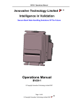
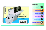
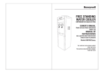
Smart Coin System User Manual Copyright © Innovative Technology Ltd 2015 GA02033 Smart Coin System User Manual Page 1 of 30 Table of Contents 1 1.1 1.2 1.3 1.4 2 2.1 2.2 2.3 3 3.1 3.2 3.3 3.4 3.5 3.5.1 3.5.2 3.5.3 3.5.4 3.5.5 3.6 4 4.1 4.2 4.3 4.4 5 5.1 5.2 5.3 5.4 6 6.1 6.2 6.3 6.4 7 8 9 DOCUMENT INTRODUCTION Document Issue Copyright Limited Warranty Product Safety Information PRODUCT INTRODUCTION General Description Key Features Typical Applications INSTALLATION Preparation Baseplate Mounting Requirements Mounting the Smart Coin System Connect the unit Configuration Configuration Button Functions Flash Counts (Interface Type) DES Trusted Mode Programming and Dataset loading SD Card Update Basic Operation MANAGING THE COINS – OPTIMUM USE Coin Level Control commands Small Coins Large Coins Filling the unit FIELD MAINTENANCE Detaching SMART Coin Feeder Clearing a Jam from the Hopper Clearing a Jam from the Feeder Fault Finding - Flash Codes MECHANICAL & ELECTRICAL DOCUMENTATION Dimensions Technical Specifications Earth Bonding Electrical Interfaces GLOSSARY OF TERMS CABLE DRAWINGS CONTACT Copyright © Innovative Technology Ltd 2015 2 2 2 2 3 4 4 4 5 6 6 6 7 8 8 8 9 9 9 9 10 11 11 11 12 12 13 13 14 17 18 20 20 21 22 22 24 27 30 GA02033 Smart Coin System User Manual Page 2 of 30 1 DOCUMENT INTRODUCTION 1.1 Document Issue Rev. Date Amendment Details Issued by -- 19/02/15 First Issue JB 1.1 4/May/2015 Added safety warning IJ 1.2 21/Jul/2015 Added Managing the coins… IJ 1.2 Copyright This manual set is Copyright © Innovative Technology Ltd. 2015. No part of this publication may be reproduced in any form or by any means used to make any derivative such as translation, transformation, or adaptation without permission from Innovative Technology Ltd. The contents of this manual set may be subject to change without prior notice. 1.3 Limited Warranty Innovative Technology Ltd warrants each of its hardware products to be free from defects in workmanship and materials under normal use and service for a period commencing on the date of purchase from Innovative Technology Ltd or its Authorized Reseller, and extending for the length of time stipulated by Innovative Technology Ltd. A list of Innovative Technology Ltd offices can be found in every section of this manual set. If the product proves defective within the applicable warranty period, Innovative Technology Ltd will repair or replace the product. Innovative Technology Ltd shall have the sole discretion whether to repair or replace, and any replacement product supplied may be new or reconditioned. The foregoing warranties and remedies are exclusive and are in lieu of all other warranties, expressed or implied, either in fact or by operation of law, statutory or otherwise, including warranties of merchantability and fitness for a particular purpose. Innovative Technology Ltd shall not be liable under this warranty if it’s testing and examination disclose that the alleged defect in the product does not exist or was caused by the customer's or any third person's misuse, neglect, improper installation or testing, unauthorized attempts to repair, or any other cause beyond the range of the intended use. In no event will Innovative Technology Ltd be liable for any damages, including loss of profits, cost of cover or other incidental, consequential or indirect damages arising out the installation, maintenance, use, performance, failure or interruption of a Innovative Technology Ltd product, however caused. Copyright © Innovative Technology Ltd 2015 GA02033 Smart Coin System User Manual Page 3 of 30 1.4 Product Safety Information Throughout this manual set, we may draw your attention to key safety points that you should be aware of when using or maintaining the product. These safety points will be highlighted in a box, like this: Caution! Mains voltage is present on these terminals This manual set and the information it contains is only applicable to the model stated on the front cover, and must not be used with any other make or model. Read before using product! Do not put a hand into the Smart Coin System while power is applied. Danger of injury! 2) It is possible for a static charge to be transferred onto the coins during normal operation. The coins should be discharged to earth before they are accessible to the user. 3) The base plate should always be connected to earth. Copyright © Innovative Technology Ltd 2015 GA02033 Smart Coin System User Manual Page 4 of 30 2 PRODUCT INTRODUCTION Feeder Smart Hopper (SH4) 2.1 General Description The SMART Coin System (SCS) is a state of the art bulk coin validator, mixed coin hopper and recycler in one. The unit validates, discriminates and stores mixed coins, eliminating coin starvation & the need for multiple hoppers. With a market leading coin hopper capacity and fully audited, efficient refills the SMART Coin System is designed to eliminate coin starvation and significantly reduce operator collection costs. Operating at a market leading 12 coins per second the SMART Coin System improves operator cash flow, significantly reducing collection costs. 2.2 Key Features • • • • State of the art bulk coin validator, hopper & recycler Eliminates coin starvation Market leading coin capacity, acceptance and payout speed Lowest cost of ownership Copyright © Innovative Technology Ltd 2015 GA02033 Smart Coin System User Manual Page 5 of 30 Floating function o When the SCS receives the command to float to a required level, coins are sent to the cash box until the requested float level remains in the hopper No need for additional sorters, hoppers or tubing o All coins validated by the coin feeder before entering the hopper. The hopper will then send all unrequired coins (not needed for future payments) to the cash box. Built in security o Modulated coin exit sensor; 128 bit AES Encrypted SSP communications (eSSP); locking option. The SMART Hopper can be used to control a coin acceptor making machine wiring and software implementation simpler. There is no need to have a separate ccTalk bus to control the coin acceptor. Only 1 SSP bus is required, the hopper then communicates with the coin acceptor using a ccTalk connection. 2.3 Typical Applications The SMART Coin System can be used in a variety of situations where coin acceptance, validation and recycling are needed. Some typical applications are: • Automated change transactions • AWP and SWP applications • Self-Serve and Retail • Kiosks • Casinos • Parking and Ticketing • Vending Copyright © Innovative Technology Ltd 2015 GA02033 Smart Coin System User Manual Page 6 of 30 3 INSTALLATION 3.1 Preparation If you received your Smart Coin System already mounted on the baseplate, remove it. 3.2 Baseplate Mounting Requirements Ensure that the mounting position and note exit hole meets the dimensional requirements as shown below (all dimensions are in millimetres mm): The coins fall from the cashbox exit chute and are intended to be caught in the host machine cashbox. Copyright © Innovative Technology Ltd 2015 GA02033 Smart Coin System User Manual Page 7 of 30 The maximum thickness of the shelf (on to which the baseplate is mounted) is 10mm – including any items which protrude below it (such as nuts, washers, screws etc.). WARNING! Ensure that there is space below the exit chute to allow the coins to fall clear of the coin exit. Ensure there is space for coins to fall clear. WARNING! Always ensure the bottom cash box exit on the underside of the SMART Hopper is clear to allow coins to exit. Failure to do so can result in permanent damage to the internal mechanisms Secure the baseplate in position using the screw holes provided. WARNING! Do not allow screw heads to foul the SMART Coin System. Ensure baseplate mounting screws are flush with the surface of the baseplate. 3.3 Mounting the Smart Coin System Slide the Smart Coin System on to the baseplate (reverse of removal). Copyright © Innovative Technology Ltd 2015 GA02033 Smart Coin System User Manual Page 8 of 30 3.4 Connect the unit Connect the cable from the host machine to the connector on the rear of the mounting plate. See Mechanical & Electrical Documentation for connection details. Apply power to the unit (host machine). 3.5 Configuration The SMART Coin System does not use DIP switches to configure the unit – configuration and setting is carried out by use of a Configuration Button on the front of the SMART Coin System body (below/left of the Led cluster): There are several functions available when using the Configuration Button, and these are listed in the next table: WARNING! Risk of unit damage When in programming mode, do not turn off the power before the operation is complete as this will make the unit unusable. 3.5.1 Configuration Button Functions Action Power Status Function Press the button, then press the button again within 5 seconds (do not double click a pause in press is required) Powered ON Switches interface between SSP and CC2. Press and hold for longer than 5 seconds Powered ON Switch between USB mode (CDE & HID) Copyright © Innovative Technology Ltd 2015 GA02033 Smart Coin System User Manual Page 9 of 30 3.5.2 Flash Counts (Interface Type) Flash Count Flash Count 1 (Flashing Slow) Interface SSP 1 (Flashing Slow together) 1 (Flashing Slow together) CC2 1 (Flashing Alternately) 1 (Flashing Alternately) DES Trusted Mode The SMART Coin System leaves the factory pre-set to at least one currency and one interface so that it is ready for immediate installation. The dataset and interface used are shown on the label fixed to the back of the SMART Coin System. 3.5.3 DES Trusted Mode When set to CC2 with DES enabled. DES trusted mode can be entered by resetting all denomination levels to 0. On a power cycle the SMART Coin System will automatically enter DES trusted mode for 2min to allow for pairing to the host. The easiest way to set all levels to zero is to run an empty cycle. 3.5.4 Programming and Dataset loading For programming and loading a new dataset in some cases it may be possible to connect to the unit using the USB connectors on the SMART Coin System. These connections are NOT for operational use. The 8 way connector should be used at all times. 3.5.5 SD Card Update Updating the SMART Coin System with a SD Card is a very quick and simple process. You require a Class 4 SD Card. A computer with a SD Card Reader The card needs to be blank formatted in the FAT32 format. Simply copy the Dataset/Firmware file on to the SD Card with the file renamed as update.cf1. Then place the SD Card in to the SD slot on the front of the Smart Coin System. During the update the LED lights will pulse at high speed. Once the update is completed the SMART coin System will reset. Copyright © Innovative Technology Ltd 2015 GA02033 Smart Coin System User Manual Page 10 of 30 3.6 Basic Operation The SMART Coin System is a device that can validate, store and later dispense a large number of mixed denomination coins. The SMART Coin System has two Light Emitting Diode (LED) indicators that are used to show the status of the unit (one Red, one Green) – these can be found on the front of the unit. If the SMART Hopper unit is operating normally, only the Green LED should be lit: when operating normally this LED will flash once every second. The SMART Coin System has inbuilt fault detection. If there is a configuration or other error, the Status Indicator LEDs will flash in a particular sequence. A summary of the Flash Codes are shown below: Copyright © Innovative Technology Ltd 2015 GA02033 Smart Coin System User Manual Page 11 of 30 4 MANAGING THE COINS – OPTIMUM USE In order to get the best from the SMART Coin System, please observe the following: a) Minimum hopper coin levels: the recommended minimum is 20 pieces of each denomination, the absolute minimum is 10 pieces of each denomination or 50 coins, whichever is less. Less than this will result in extended search times for the correct coin or even time-outs. b) Maximum hopper coin levels: the maximum is determined by the physical level (height) of the coins held. This is observed and reported by the ‘Full Sensor’ (optical) in the hopper bowl. It reports using the ‘Device Full’ 0xCF SSP event. The actual number of coins to reach this level varies with coin sizes and mix. Typical values are approximately 1500 coins. The host should use the Coin Level Control commands to ensure that the maximum is not exceeded. 4.1 Coin Level Control commands Coin levels can be controlled using one or more of the following commands: Float Amount 0x3D: This will float the unit to leave the requested value in the unit. Its benefits are: a) Overall Value Control b) Calculations are done for you by the SCS Float by Denomination 0x44: This will float the unit on an individual coin by coin basis to ensure the actual coin levels remain. Its benefits are: a) Exact coin levels b) The absolute maximum of the coins is not exceeded (see above) c) A good mix of coins at all times to meet the payout values required. Set Cashbox Payout Limit 0x4E Allows the host to specify a maximum level of each coin, by denomination, to be left in the hopper. Its benefits are: a) Floating (paying to cashbox) is done ‘invisibly’ b) Levels are reached automatically c) No out-of-service time while floating takes place 4.2 Small Coins Coins below 18mm diameter require special considerations. €0.01 (EUR 1 cent) During normal operation (payout or stir) the number of €0.01 in the hopper should not exceed 20 or 15% of the total coins – whichever is greater. If the €0.01 coins exceed this level the SCS will automatically try to dump the excess to cashbox during any payout operation. Copyright © Innovative Technology Ltd 2015 GA02033 Smart Coin System User Manual Page 12 of 30 If the €0.01 coins exceed this level they should be reduced, as quickly as possible, using the Coin Level Controls commands. 4.3 Large Coins Large coins (coins larger than the largest in the dataset) can block the recesses in the Coin Feeder disk. In the worst cases this would mean that the normal coins cannot be fed into the hopper. It is extremely unlikely that this would happen in normal operation. Even so, the SCS monitors for this and if this happens, after a coin feeder activation zero coins are seen in the validation area then the unit will issue a Maintenance Required SSP message (0xC0). This is a warning that the host machine can use to call the site operator to check the unit. 4.4 Filling the unit When filling with a roll of coins put only one roll of coins into the feeder at one time. Wait for the coins to be completely processed before introducing more coins. If filling with rolls of different denominations, if possible use the rolls in a mixed order i.e. do not put all the same denomination in at the same time. This will help mix the coins from the start. When filling with mixed coins, insert 150 coins maximum at one time. Wait for these to be processed before introducing more coins. Note: During refill some coins may be rejected in the normal way. These should be re-entered once the previous lot have been processed. Stirring Stirring is the way of mixing the coins without actually paying any coins out. After filling the SCS it is recommended that the Coin Stir command is issued (0x5D) with a duration of at least 30 seconds. This will help to ensure optimum payout times for the customer. Copyright © Innovative Technology Ltd 2015 GA02033 Smart Coin System User Manual Page 13 of 30 5 FIELD MAINTENANCE This section contains the essential information that the field engineer needs to clean, maintain and fault find a SMART Coin System that is installed in a host machine. The SMART Coin System has been designed to minimise any problems or performance variations over time. This has been achieved by careful hardware and software design; this attention to the design means there is very little user maintenance required. 5.1 Detaching SMART Coin Feeder The below pictures highlight the button location to detaching the different parts. 1. 2. 3. 4. The Feeder can be detached from the Hopper pulling up the button. Then Lift the lid of the feeder by lifting the front tab. The feeder should now slide off the hopper as shown below. Push the Feeder back until it stops and lift the Feed from the Hopper. Copyright © Innovative Technology Ltd 2015 GA02033 Smart Coin System User Manual Page 14 of 30 5.2 Clearing a Jam from the Hopper 1. Power off the SCS and remove 24volt 4 way power cable. 2. Remove the hopper from the mounting plate 3. Empty all coins from the coin bowl 4. Clear the jammed coin from the disk Coins will drop out here Turn coil anti-clockwise but be cautious to avoid harm. Copyright © Innovative Technology Ltd 2015 GA02033 Smart Coin System User Manual Page 15 of 30 5. Remove coin cover (fraud cover) Remove fraud cap 6. Re-move the front panel. From the top pull down and right (twist) and the panel clips off. 7. Once the cover is removed check the pistol is not sticking and that the sensor is clean, see picture below. Copyright © Innovative Technology Ltd 2015 GA02033 Smart Coin System User Manual Page 16 of 30 Clean Sensor and pistol. 8. Re-fit all parts 9. Re-attach the hopper to the mounting base plate and the feeder 10. Re-fill the hopper and apply levels to host. 11. Apply power 12. Test operation Copyright © Innovative Technology Ltd 2015 GA02033 Smart Coin System User Manual Page 17 of 30 5.3 Clearing a Jam from the Feeder Before attempting to clear the jam you must ensure the power has been removed. 1. Empty all coins from the funnel. 2. Lift the catch on the front of the feeder and lift the lid back. 3. Clear the jammed coin from the disk and ensure it is free to rotate. 4. Wipe the track of any coin dust. 5. Ensure the diverter flap is able to move, the flap should be capable of opening onto the coin path. 6. Once all of the coins have been cleared ensure the drive gear isn’t impeded. 7. Close the lid of the feeder and reapply power. 8. Check for normal operation. Coin Disk Drive Gear Diverter flap Copyright © Innovative Technology Ltd 2015 GA02033 Smart Coin System User Manual Page 18 of 30 5.4 Fault Finding - Flash Codes The Smart Hopper module has inbuilt fault detection. If there is a configuration or other error, the Smart Hopper module LED’s well indicates will flash in a particular sequence. The Smart Hopper module status indicators are on the front of the Smart Hopper module, seen below: Status LED’s Copyright © Innovative Technology Ltd 2015 GA02033 Smart Coin System User Manual Page 19 of 30 A summary of the Status Indicator Flash Codes for the payout module are shown here: Led Colour Status Description Green Flashing 1Hz Enabled and ready to dispense Red 1 Flash Hopper disabled Host system to send enables command. Red 2 Flashes Calibration Fault Optical sensor contaminated. Operator to clean exit sensor light pipe. If fault persists, return to ITL for service. Red 3 Flashes No Encryption key set Host system to negotiate key. Red 4 Flashes Coin jammed Remove power, manually empty coins from bowl and check hopper base for stuck coins. Try manually turning the disc. Persistent jam may require returning to ITL for service. Red 5 Flashes Fraud Attempt detected. Reset hopper. If this persists it indicates a problem with the top pay-out flap, light guide or exit sensor. Red 6 Flashes Legacy, no longer used. (Hopper empty) Red 7 Flashes Memory checksum error Re-download hopper firmware. If this persists return to ITL for service. Red 8 Flashes Hopper sensors not initialised Return to ITL for service. Red 9 Flashes Legacy, no longer used. (Lid removed). Copyright © Innovative Technology Ltd 2015 Action GA02033 6 MECHANICAL & ELECTRICAL DOCUMENTATION 6.1 Dimensions Copyright © Innovative Technology Ltd 2015 GA02033 6.2 Technical Specifications Power Requirements Recommended Voltage 24V Minimum Voltage 21.6V Maximum Voltage 26.4V Standby Supply Current 200mA Running Supply Current 3A Peak Supply Current 6.5A Recommended PSU 7A Warranty 12 Months Min 18mm 1.65mm Diameter Thickness Weight Performance & Reliability Empty 4kg Full 18kg (approx) MCBF (cycle) 150,000[1] MCBI (cycles) 50,000[1] Acceptance[4] Acceptance (3rd time)[4] 95% Duty Cycle Cycle Time Maintainable Life Media Specifications Max Capacity 28.5mm 3.2mm Environmental Specifications Maximum Temperature + 50°C Minimum Temperature + 3°C Maximum Humidity 95% NC Minimum Humidity 5% 97.00% 1,000,000 cycles 1500 x €1 1200 x £1 Supported Interfaces (e)SSP over ~TTL, cctalk (CC2) ~TTL levels: Inputs: 0.5V max = 0, 3.7V min = High internal pullup Outputs: o/collector 0.6V min = Low Max current sink 50mA Preventative Maintenance Schedule: - Every 10,000 cycles check belt to ensure it is in good condition. Clean optical level switch on the inside. - Every 50,000 cycles clean coin dust. Standards & Approvals: IEC 61249-2-21 Materials for PCBs. [2] CE/RoHS/WEEE IEC/UL 60950 Safety (CB Scheme) Notes: [1] [2] [3] To be confirmed by testing In progress - not yet certified Street grade true notes (GBP) Please ensure suitable cable is used for power and communication connections. Copyright © Innovative Technology Ltd 2015 GA02033 Smart Coin System User Manual Page 22 of 30 6.3 Earth Bonding It is very important that the base plate is bonded to earth, as lack of proper bonding can cause communication issues and failures with the SMART Coin System. The earth bond should be made to any of the 6 holes in the bottom of the base plate and be bonded to mains earth, typically through the Power Supply Unit. Information The resistance between the base plate and the Earth pin on the mains plug should be less than 0.7 ohms. Earth resistance. 6.4 Electrical Interfaces SMART Hopper All the connectors needed to set up the SMART Coin System are easily accessible on the bottom base: there are two connectors that are used to allow interfacing and programming: Information Power is always required on pins 3 and 4 of the 4 way connector. Power always required regardless of connection type. The first connector is a 4 pin socket used to power up the SMART Hopper. Pin 3 Pin 2 Pin 4 Pin 1 Copyright © Innovative Technology Ltd 2015 Pin Description 1 +24V DC 2 0V / Ground Connection 3 N/C 4 N/C GA02033 Smart Coin System User Manual Page 23 of 30 Interface communication from the SMART Hopper unit to the host machine can communicate via SSP or CCT. The SSP pin numbering of the socket is shown below, as well as an overview of the socket connections: Pin 1,3&4 Description N/C 2 0V / Ground Connection 7 Serial Data Out (Tx) 8 Serial Data In (Rx) The USB connector is a standard Type B USB socket. The USB socket can be used for programming the SMART Hopper unit and also bench testing – a USB 2.0 compliant Type ‘A’ to ‘B’ lead can be used to do this. USB cables should be electrically shielded and less than 5 metres long. Please note: Direct USB should NOT be used for Host communications. If USB is required than our IF17 (TTL to USB) should be used. Copyright © Innovative Technology Ltd 2015 GA02033 Smart Coin System User Manual Page 24 of 30 7 GLOSSARY OF TERMS Term Meaning A Ampere AC Alternating Current ACK Acknowledge AES Advanced Encryption Standard ASSY Assembly AV Average AWG American Wire Gauge AWP Amusement With Prizes BNV Bank Note Validator ccTalk Coin Controls Talk COMMS Communications CRC Cyclic Redundancy Check DC Direct Current DIA Diameter DIP Dual Inline Package ECB Electronic Code Book EEPROM Electrically Erasable Programmable Read Only Memory eSSP Encrypted Smiley® Secure Protocol FAQ Frequently Asked Questions GA General Assembly GND Ground Hz Hertz Copyright © Innovative Technology Ltd 2015 GA02033 Smart Coin System User Manual Page 25 of 30 ITL Innovative Technology Ltd LED Light Emitting Diode mA milliampere max maximum MDB Multi Drop Bus min minimum mm millimetre ms millisecond MOD Modified (or Modification) NV Note Validator PCB Printed Circuit Board PDF Portable Document Format PiPS Pay-in Pay-out System PROM Programmable Read Only Memory PSU Power Supply Unit QTY Quantity RAM Random Access Memory ROM Read Only Memory Rx Receive RoHS Restriction of the use of certain Hazardous Substances SIO Serial Input Output SSP Smiley® Secure Protocol SWG Standard Wire Gauge SWP Skill With Prizes SYNC Synchronize Copyright © Innovative Technology Ltd 2015 GA02033 Smart Coin System User Manual Page 26 of 30 TTL Transistor Transistor Logic Tx Transmit USB Universal Serial Bus V Volt V_In Voltage In WEEE Waste Electrical and Electronic Equipment Copyright © Innovative Technology Ltd 2015 GA02033 Smart Coin System User Manual Page 27 of 30 8 CABLE DRAWINGS Copyright © Innovative Technology Ltd 2015 GA02033 Smart Coin System User Manual Copyright © Innovative Technology Ltd 2015 Page 28 of 30 GA02033 Smart Coin System User Manual Copyright © Innovative Technology Ltd 2015 Page 29 of 30 GA02033 Smart Coin System User Manual Page 30 of 30 9 CONTACT MAIN HEADQUARTERS Innovative Technology Ltd Derker Street – Oldham – England - OL1 4EQ Tel: +44 161 626 9999 Fax: +44 161 620 2090 E-mail: [email protected] Web site: www.innovative-technology.co.uk BRAZIL [email protected] CHINA [email protected] GERMANY [email protected] SPAIN [email protected] UNITED KINGDOM [email protected] UNITED STATES OF AMERICA [email protected] REST OF THE WORLD [email protected] Copyright © Innovative Technology Ltd 2015 GA02033