1
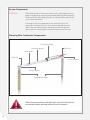
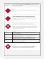
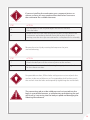
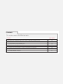
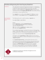
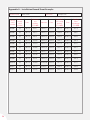
Man 117
Vibrating Wire
Crackmeter
User Manual
Soil Instruments Limited has an ongoing policy of design review and reserves the right to amend these specifications without notice.
Man117 - Vibrating Wire Crackmeter - MN0814 - Rev1.0.1
1
What’s this manual about? This manual tells you about the Vibrating Wire Crackmeter
and how to use it to monitor crack displacement.
Who does this apply to?
Installers, field engineers and technicians who need to measure
crack displacement using a Vibrating Wire Crackmeter.
QUESTION
2
Welcome!
Thank you for choosing the Vibrating Wire Crackmeter.
This manual has been written to provide you with relevant
information and to guide you in best practice when using
a Vibrating Wire Crackmeter in order for you to gain the
most from our product.
Please read this manual thoroughly before use to help
avoid any problems and keep it handy when using a
Vibrating Wire Crackmeter.
Vibrating Wire Crackmeter
The Vibrating Wire Crackmeter provides accurate
measurement of crack propagation for structural
or geotechnical monitoring.
The sensor is made from high quality Stainless Steel,
incorporates ‘O’ ring seals to allow for underwater use
and is designed for long-term, reliable monitoring.
Fitted across a crack or joint, the sensor monitors
displacement by detecting a change in tension in
the Vibrating Wire inside the sensor.
The Vibrating Wire Crackmeter provides accurate,
repeatable readings over long cable lengths
combined with a long working life and long-term
stability and reliability.
3
Contents
PART I – GENERAL USER GUIDE
6
Introduction:8
Important Information8
Product8
Changes8
Warranty8
Disposal8
System Description9
Things You Need to Know About the Vibrating Wire Crackmeter
9
Features9
Benefits9
System Components10
Overview10
Vibrating Wire Crackmeter Components10
Quick Guide to Using the Vibrating Wire Crackmeter
11
Preliminary Test11
Installing the Sensor12
Wiring Identification15
Splicing the Cable15
PART II – DATA REDUCTION & TEMPERATURE CORRECTION
16
Calculation of Engineering Units From Frequency Based Units
18
Overview18
Calculation Using Period Units
18
Calculation Using Linear Units
19
Linear Unit Calculation Using a Polynomial Equation
19
Temperature Correction 20
Environmental Factors21
PART III – APPENDICES22
Appendix A – Installation Record Sheet Example 24
Appendix B – Troubleshooting Guide
25
Appendix C – Calibration Sheet Example
27
4
PRECISELY MEASURED
instrumentation and monitoring
5
Part I – General
User Guide
6
Contents
This section contains the following topics.
TOPIC
Introduction:
Important Information
Product
Changes
Warranty
Disposal
System Description
Things You Need to Know About the Vibrating Wire Crackmeter
Features
Benefits
System Components
Overview
Vibrating Wire Crackmeter Components
Quick Guide to Using the Vibrating Wire Crackmeter
Preliminary Test
Installing the Sensor
Wiring Identification
Splicing the Cable
SEE PAGE
8
8
8
8
8
8
9
9
9
9
10
10
10
11
11
12
15
15
7
Introduction:
Important Information
The following symbols are used throughout the manual
IMPORTANT
INFORMATION
QUESTION
WARNING
TIP
! Important: Failure to adhere to the warnings in this manual
may result in network disruption and possible data loss.
Failure to observe the warning may result in injury, product
malfunction, unexpected readings or damage to the product
that may invalidate its warranty.
WARNING
Tips give additional information that may be helpful when using a
Vibrating Wire Crackmeter.
TIP
PRODUCT
CHANGES
Soil Instruments has an on-going policy of design review and
reserves the right to amend the design of their product and this
instruction manual without notice.
WARRANTY
Refer to our terms and conditions of sale for warranty information.
The batteries are a consumable item and are excluded from
the warranty.
DISPOSAL
Products marked with the symbol are subject to
the following disposal rules in European countries:
• This product is designated for separate collection at an
appropriate collection point
• Do not dispose of as household waste
• For more information, contact Soil Instruments or the local
authority in charge of waste management.
WEE/DE3326WV
8
System Description
Things You Need to Know About the Vibrating Wire Crackmeter
FEATURES
•
•
•
•
•
Uses proven Vibrating Wire technology
Ideal for long-term monitoring
Suitable for manual or remote monitoring
Fully waterproof
Fitted with thermistor for temperature monitoring
BENEFITS
•
•
•
•
Accurate, repeatable readings over long cable lengths
Long working life
Long-term stability and reliability
Connecting cable is strong, screened and flexible
9
System Components
OVERVIEW
The Vibrating Wire Crackmeter consists of a telescoping sensor
body incorporating a sprung, tensioned Vibrating Wire element.
Each end of the telescoping body is anchored either side of the
crack to be monitored.
A change in distance between the anchors by the crack
opening or closing will cause the connecting rod to move
within the transducer body, changing the tension on the
spring and thus altering the resonant frequency of the wire.
Vibrating Wire Crackmeter Components
Transducer body
Connecting rod
Wire clip
Locking pin
Wire clip
Universal joint
Universal joint
Groutable anchors
Follow the precautions outlined in this manual at all times to
ensure the correct working order of your instrument
WARNING
10
Quick Guide to Using the Vibrating Wire Crackmeter
Soil Instruments recommend an intermediate skill level for installing a
Vibrating Wire Crackmeter.
It is essential that the equipment covered by this manual is
handled, operated and maintained by competent and suitably
qualified personnel.
IMPORTANT
INFORMATION
The connecting rod must be withdrawn and re-inserted into
the body in a controlled manner, as withdrawing and releasing
the rod will result in it returning into the body at speed and
damaging the Vibrating Wire element.
WARNING
The rod is connected directly to the wire via the spring; therefore
the rod should not be rotated or extended beyond the range of
the instrument at any point during the installation process as
this will cause damage to the Vibrating Wire element.
WARNING
PRELIMINARY
TEST
• Unpack the Vibrating Wire Crackmeter and familiarise yourself
with the product
• Connect the wires from the crackmeter cable to a readout unit
• Pull the connecting rod out to approximately 3mm
• Check that the reading is stable for the crackmeter
(and thermistor if included)
• Record the reading for the crackmeter (and thermistor if included)
For further information on Vibrating Wire readouts, please refer
to datasheets RO-1-VW-NOTE Vibrating Wire Note and
RO-1-VW-READ Vibrating Wire Readout which can be downloaded
from either our website www.itmsoil.com or our support site
www.itmsoilsupport.com.
You must perform the preliminary test on each sensor before
you install it.
IMPORTANT
INFORMATION
11
INSTALLING THE
SENSOR
Soil Instruments recommend an intermediate skill level for installing a
Vibrating Wire Crackmeter.
The crackmeter may be installed with groutable or expanding
shell anchors.
IMPORTANT
INFORMATION
To allow for compression of the crack to be monitored, it is
recommended that the sensor is installed with 25% of the
available range of the instrument reserved for compression
and 75% available for extension.
IMPORTANT
INFORMATION
When you have established the installed distance between
the anchors, which is the length of the crackmeter, measured
between the centres of the universal joints, plus 25% of the range
of the instrument, a drill template can be made to make multiple
installations quicker and easier.
TIP
STEP
ACTION
1
Measure the length of the crackmeter from the centres of the
universal joint sockets
2
Add 25% of the range of the instrument to the length of the
crackmeter measurement
3
Mark out the locations for drilling at either side of the crack,
with the crack central, using the determined measurement
4
Measure the depth of the chosen anchors to establish the
depth of the hole to be drilled
Once you have measured the correct depth for the anchors,
mark the drill bit with insulation tape to avoid drilling the holes
to deep/shallow and to save time on multiple installations.
TIP
12
If you are installing the crackmeter over a segment joint or an
uneven surface, you may need to offset the anchors to ensure
the crackmeter has suitable clearance.
IMPORTANT
INFORMATION
STEP
ACTION
5
Drill the holes to the required depth and extract the dust
from the holes
6
Remove the wire clips from the universal joints at each end of the
crackmeter and remove the balls from the sockets of the joints,
making sure the wire clips are retained in a safe place for re-assembly
Remove the wire clip by rotating the loop over the joint
and withdrawing.
TIP
STEP
ACTION
7
Attach the ball parts of the universal joints to the anchors
8
Place the anchors into the holes using the appropriate method
for the chosen anchors
For groutable anchors, fill the holes with grout or resin and push the
anchors in place and allow to set. For expanding shell anchors push
the anchors into the holes and expand by tightening the anchor bolt.
TIP
The connecting rod must be withdrawn and re-inserted into the
body in a controlled manner, as withdrawing and releasing the rod
will result in it returning into the body at speed and damaging the
Vibrating Wire element.
WARNING
13
STEP
ACTION
Refit the crackmeter to the ball joints on the anchors by attaching the
cable end of the instrument first and re-inserting the clip, followed by
the opposite end
9
Push the socket at the cable end of the crackmeter over the ball
on the anchor and re-insert the clip through the holes on the side
of the joint socket, then rotate the loop over the joint into its
original position. Withdraw the rod end and position over the ball on
the second anchor and hold in place until the clip has been re-fitted.
TIP
STEP
10
ACTION
Record the reading of the crackmeter (and thermistor if included)
and the sensor serial number and retain in a safe place as the base
(zero) reading of the instrument for data interpretation.
Please refer to Datasheets RO-1-VW-NOTE Vibrating Wire Note
and RO-1-VW-READ Vibrating Wire Readout for details on Soil
Instruments Vibrating Wire handheld readouts.
Make sure you record the readings from each crackmeter
(and thermistor if included) during the preliminary test and
after the installation as well as the sensor serial number and
its location. Please refer to Part III – Appendices – Appendix A Installation Record Sheet Example in this manual for details.
WARNING
14
Wiring Identification
The four wires from the crackmeter are identified in the table below:
WIRE COLOUR
SPLICING THE
CABLE
IDENTIFICATION
Red
Crackmeter sensor +
Black
Crackmeter sensor -
Green
Thermistor +
White
Thermistor -
Shield
Shield
Because Vibrating Wire transducers output frequency or period,
a direct derivative of frequency rather than current or voltage,
slight variations in cable resistance have no detrimental effect
on the readings.
Consequently, splicing has no effect on instrument performance
allowing cables to be spliced and routed to junction boxes and
then connected to multi-conductor cables for transmission to
a central location.
15
Part II –
Data Reduction
& Temperature
Correction
16
Contents
This section contains the following topics.
TOPIC
Calculation of Engineering Units From Frequency Based Units
Overview
Calculation Using Period Units
Calculation Using Linear Units
Linear Unit Calculation Using a Polynomial Equation
Temperature Correction
Environmental Factors
SEE PAGE
18
18
18
19
19
20
21
17
Calculation of Engineering Units From Frequency Based Units
OVERVIEW
The mathematical relationship between the frequency of vibration of
a tensioned wire and the force applying the tension is an approximate
straight line relationship between the square of the measured
frequency and the applied force. ‘Engineering units’ of measurement
maybe derived from the ‘frequency based units’ measured by vibrating
wire readouts, in three traditional ways;
From ‘period’ units (t x 107) and from ‘linear’ (f^2/1000) units using
two methods; a simple ‘linear’ equation or a ‘polynomial’ equation.
CALCULATION
USING PERIOD
UNITS
The following formula is used for readings in ‘period’ units.
‘E = K (10^7/P0^2 – 10^7/P1^2)’
Where;
‘E’ is the ‘pressure’ in resultant ‘engineering units’,
‘K’ is the ‘period gauge factor’ for units of calibration
(from the calibration sheet)
‘P0’ is the installation ‘period base’ or ‘zero’ reading
‘P1’ is the current ‘period’ reading.
This method of calculation is used by Soil Instruments Vibrating Wire
loggers’ (models ‘RO-1-VW’ and with serial numbers starting ‘VL’ or ‘TVL’)
internal processors, for calculating and displaying directly on the
loggers’ LCD screen, the required ‘engineering based units’.
The loggers’ require ‘period base’ or ‘zero’ reading units for entering
into their channel tables, to calculate and display correctly the required
‘engineering units’.
If an ‘engineering based unit’ is required other than the units of
calibration, then the correct ‘K’ factor will have to be calculated using
the standard relationship between ‘engineering units’. For example,
if the units of ‘engineering’ required were in inches (“) and the
calibration units were millimetres (mm), we we can conclude
that 1mm, is equal to 0.03937 “, so we would derive the ‘K’ factor
for inches by multiplying the ‘K’ factor for millimetres by 0.03937.
A negative sign represents a decrease in length across the
crackmeter anchor points.
IMPORTANT
INFORMATION
18
CALCULATION
USING LINEAR
UNITS
The following formula is used for readings in ‘linear’ units.
E = G (R0 – R1)
Where;
‘E’ is the resultant ‘engineering unit’,
‘G’ the ‘linear gauge factor’ for the units of calibration
(from the calibration sheet)
‘R0’ is the installation ‘linear base’ or ‘zero’ reading
‘R1’ is the current ‘linear’ reading.
The ‘linear gauge factor’ for units other than the units of calibration
would need to be calculated using the same principles as stated in
the ‘Calculation Using Period Units’ section.
LINEAR UNIT
CALCULATION
USING A
POLYNOMIAL
EQUATION
‘Linear’ units may be applied to the following polynomial equation,
for calculation of ‘engineering units’ to a higher order of accuracy.
E = AR1^2 + BR1 + C
Where;
‘E’ is the resultant ‘engineering unit’
‘A’, ‘B’ and ‘C ‘ the ‘polynomial gauge factors’ (from the calibration sheet)
‘R1’ is the current ‘linear’ reading.
The value ‘C’ is an offset value and relates to the ‘zero’ value experienced
by the transducer at the time of calibration.
This value should be re-calculated at the installation time as follows;
C = - (AR0^2 + BR0)
Where;
‘A’ and ‘B’ are as above,
‘R0’ is the installation ‘linear base’ or ‘zero’ reading.
Please note that the sign of the re-calculated value of ‘C’, should be
the same as the original value of ‘C’, so if the original is negative then
the re-calculated value should also be negative.
Conversion to ‘engineering units’ other than the units of calibration,
would best be done after conversion, using a factor calculated
using the same principles as stated in the ‘Calculation Using
Period Units’ section.
19
Temperature Correction
The Vibrating Wire Crackmeter working elements are made primarily
of steel and Stainless Steel and are affected by changing temperature
to a certain predictable degree. In case of large temperature changes,
application of temperature correction will improve the accuracy of
the measurements.
The approximate temperature effect on the gauge is;
-0.02mm per °C
therefore a temperature increase of 10°C, will indicate;
(-0.02mm x 10) -0.2mm
to the result indicated by the crackmeter reading.
A fall in temperature will result in a positive change in linear
measurement which can be corrected accordingly.
Barometric pressure changes do not affect the crackmeter reading.
20
ENVIRONMENTAL
FACTORS
Since the purpose of the crackmeter installation is to monitor site
conditions, factors which may affect these conditions should always
be observed and recorded.
Seemingly minor effects may have a real influence on the behaviour
of the structure being monitored and may give an early indication of
potential problems.
Such factors include but are not limited to;
•
•
•
•
•
•
•
•
•
Blasting
Rainfall
Tidal levels
Excavation, fill levels and sequences
Site traffic
Temperature and barometric changes
Changes in personnel reading the instruments
Nearby construction activities
Seasonal changes
21
Part III –
Appendices
22
Contents
This section contains the following topics.
TOPIC
Appendix A – Installation Record Sheet Example Appendix B – Troubleshooting Guide
Appendix C – Calibration Sheet Example
SEE PAGE
24
25
27
23
Appendix A – Installation Record Sheet Example
Installer name
24
John Smith
Site name
Sensor
serial
number
Cal cert
(match
serial
number)
Date
Preliminary
test
reading
(F2/1000)
040901
Yes
01/01/14
4541.1
040902
Yes
01/01/14
040903
Yes
040904
Example Site
Installed
25% range
reading
(F2/1000)
Date
Reading
from
datalogger
(F2/1000)
NB bay 1 01/01/14
5671.2
02/01/14
5671.4
4562.2
NB bay 2 01/01/14
5669.3
02/01/14
5669.1
01/01/14
4489.1
NB bay 3 01/01/14
5648.3
02/01/14
5648.5
Yes
01/01/14
4550.3
NB bay 4 01/01/14
5667.2
02/01/14
5667.3
040905
Yes
01/01/14
4543.4
NB bay 5 01/01/14
5675.9
02/01/14
5675.7
040906
Yes
01/01/14
4540.8
NB bay 6 01/01/14
5637.2
02/01/14
5637.1
040907
Yes
01/01/14
4520.2
NB bay 7 01/01/14
5621.2
02/01/14
5621.1
040908
Yes
01/01/14
4529.6
NB bay 8 01/01/14
5632.3
02/01/14
5633.1
040909
Yes
01/01/14
4539.1
NB bay 9 01/01/14
5642.1
02/01/14
5641.9
040910
Yes
01/01/14
4540.4
NB bay10 01/01/14
5672.5
02/01/14
5672.1
040911
Yes
01/01/14
4552.3
NB bay11 01/01/14
5665.3
02/01/14
5664.9
040912
Yes
01/01/14
4549.8
NB bay12 01/01/14
5657.2
02/01/14
5656.9
Location
Date
Appendix B – Troubleshooting Guide
Before any of the steps below are followed, a Vibrating Wire readout unit
should be used to verify the stability of the reading.
The method used to verify the signal will be dependent on which type
of VW readout is being used; all Soil Instruments readouts use ‘FFT’
analysis, where as some other manufacturers use ‘audio’ signal.
Please refer to the manufacturers’ user manual for details on the
method required for verifying signal strength.
WARNING
Please refer to Datasheets RO-1-VW-NOTE Vibrating Wire Note
and RO-1-VW-READ Vibrating Wire Readout for details on Soil
Instruments Vibrating Wire handheld readouts.
Wildly fluctuating readings from the sensor (or an unsteady audio
signal) are both indications of possible problems with the instrument
or related electrical cables.
If the readout is giving faulty readings or audio signals from
all of the crackmeters, a faulty readout unit and/or lead must
be suspected. Another lead/readout unit should be used to
check the readings. If there is a fault with the readout unit,
please contact www.itmsoilsupport.com for assistance.
IMPORTANT
INFORMATION
STEP
ACTION
The resistance across the two conductors of the electrical cable
should be tested using a multimeter. Check the resistance across
the two conductors, either at the end of the cable if available,
or at the corresponding terminals if wired into a Datalogger.
1
The resistance across the two conductors should be approximately
120Ωto 180Ω. The majority of this resistance will come from the
crackmeter, approximately 130Ω, with the remainder from the
electrical cable connected to the transducer (for 22 gauge copper,
resistance is approximately 1Ω /15m).
Before proceeding, the continuity should be checked between
conductors and the earthing screen of the electrical cable.
If continuity exists, a damaged cable is confirmed.
25
Appendix B – Troubleshooting Guide Continued
STEP
2
ACTION
If the resistance across the two conductors is much higher than
the values quoted in ‘STEP 1’, or is infinite, a severed cable must
be suspected.
If the location of the cable damage is found, the cable can be
spliced in accordance with recommended procedure.
If the resistance across the two conductors is much lower than
the values quoted in ‘STEP 1’, (less than 80 Ω) it is likely that cable
damage has occurred causing a ‘short’ in the circuit.
3
It is possible to calculate approximately how far from the cable end
(or readout location) the suspected fault is. If the resistance of a
known length of conducting cable is measured, a resistance/length
unit can be found. This figure can be used to calculate the length of
the conductor cable in between the readout location and the break
in the circuit. If the location of the cable damage is found, the cable
can be spliced in accordance with recommended procedure.
This method is only applicable if the ‘short’ occurs between the
two conductors of the electrical cable. Since cables are generally
buried or hidden it is may not be possible to confirm a ‘short’ is
of this nature using this method.
IMPORTANT
INFORMATION
STEP
4
26
ACTION
If the resistance is within the values quoted in ‘STEP 1’ and no
continuity exists between the conductor and the earth screen
AND the reading from the crackmeter is unstable or wildly
fluctuating, it must be assumed that the integrity of the circuit
is good and the fault lies within the crackmeter. In this case
please contact our support team at itmsoilsupport.com.
Appendix C – Calibration Sheet Example
27
SUPPORT
www.itmsoilsupport.com
+44 (0) 1825 765044
Bell Lane, Uckfield, East Sussex
TN22 1QL United Kingdom
28
t:
f:
+44 (0) 1825 765044
+44 (0) 1825 744398
e: [email protected]
w: www.itmsoil.com