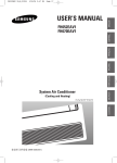
1
Man 233
Smart In-Place
Inclinometer (IPI)
User Manual
Soil Instruments Limited has an ongoing policy of design review and reserves the right to amend these specifications without notice.
Man233 - Smart In-Place Inclinometer (IPI) - MN0814 - Rev1.0.1
1
What’s this manual about? This manual tells you about the Smart In-Place Inclinometer
(Smart IPI) and how to use it to take measurements of lateral
displacement within a borehole.
Who does this apply to?
QUESTION
2
Installers, field engineers and technicians who need to measure
lateral displacement within a borehole.
Welcome!
Thank you for choosing the Smart In-Place Inclinometer (IPI).
This manual has been written to help you utilise all of the
functions of the Smart IPI. Please read this manual thoroughly
before use to help avoid any problems and keep it handy when
using the Smart IPI.
Smart In-Place Inclinometer (IPI)
A Smart In-Place Inclinometer (Smart IPI) system is used to
remotely monitor lateral displacement within a borehole.
The Smart IPI has been designed to supersede traditional
IPI systems; with advanced single cable technology and
new mechanical design, the Smart IPI is seen as a new
product rather than just an improvement to the old.
The Smart IPI System comprises in its most basic form a
Data Acquisition system, a Sensor Interface Module (S.I.M),
one Top Support Assembly, up to 39 Smart IPI Sensors and
one Terminating Sensor.
Contained within the Smart IPI Sensor body is a PCB and
two MEMS sensors. The data is transmitted via the single
cable that runs from the bottom of the borehole at the
Terminating Sensor, up to the top of the borehole through
up to 39 standard sensors and the Top Support Assembly.
This cable plugs into a Sensor Interface Module (S.I.M.)
which is connected to a Datalogger, both housed together
within an enclosure at the surface.
Each Smart IPI Sensor is connected to the next using an
Easy-Connect Coupling, starting with a Terminating Sensor
and culminating in a Top Support Assembly with an easily
adjustable setting bar. A Top Support spans the pre-installed
casing which holds the Smart IPI in place in a vertical borehole,
or maintains its position in a horizontal borehole.
The Smart IPI incorporates a Support Wire System to aid
with removal and to prevent loss or damage to the string
of the Smart IPI Sensors, should the assembly slip or be
accidentally dropped.
3
Contents
PART I – OVERVIEW6
Introduction:8
Important Information8
Product8
Changes8
Warranty8
Disposal8
System Description9
Things You Need to Know About the Smart IPI System
9
Features9
Benefits9
System Components9
For Each Borehole You Will Need:
9
Per 40 Smart IPI Sensors You Will Need:
9
Smart IPI Terminating Sensor10
Smart IPI Sensor10
Top Support Assembly11
Sensor Interface Module (S.I.M.)
12
Smart IPI System12
Quick Start Guide to Installing the Smart IPI System
13
Before You Go to Site:13
When You Are in the Field:
13
PART II – DETAILED SMART IPI INSTALLATION GUIDE
16
Installing the Smart IPI 18
Tools Required18
How to Install Smart IPIs
18
Terminating Sensor and Support Wire
19
Connecting the Sensors21
Connecting & Lowering the First Sensors
22
Connecting & Lowering Subsequent Sensors
23
Last Sensor & Top Support Assembly
24
Sensor Interface Module (S.I.M)
25
4
PART III - DETAILED SENSOR INTERFACE MODULE (S.I.M.) GUIDE
26
Sensor Interface Module (S.I.M.) 28
Overview28
Status LEDs28
Connecting the Smart IPI String to the (S.I.M.)
29
Logger Control29
S.I.M. Wiring Code29
Power Requirements29
PART IV – APPENDICES30
Appendix A - Installation Sheet Example
32
Blank Installation Sheet33
Appendix B - Datalogger Wiring Diagram34
PRECISELY MEASURED
instrumentation and monitoring
5
Part I – Overview
6
Contents
This section contains the following topics.
TOPIC
Introduction:
Important Information
Product
Changes
Warranty
Disposal
System Description
Things You Need to Know About the Smart IPI System
Features
Benefits
System Components
For Each Borehole You Will Need:
Per 40 Smart IPI Nodes You Will Need:
Smart IPI Terminating Sensor
Smart IPI Sensor Sensor
Top Support Assembly
Sensor Interface Module (S.I.M.)
Smart IPI System
Quick Start Guide to Installing the Smart IPI System
Before You Go to Site:
When You Are in the Field:
SEE PAGE
8
8
8
8
8
8
9
9
9
9
9
9
9
10
10
11
12
12
13
13
13
7
Introduction:
Important Information
The following symbols are used throughout the manual
IMPORTANT
INFORMATION
QUESTION
WARNING
TIP
! Important: Failure to adhere to the warnings in this manual
may result in network disruption and possible data loss.
Failure to observe the warning may result in injury, product
malfunction, unexpected readings or damage to the product
that may invalidate its warranty.
WARNING
Tips give additional information that may be helpful when using the
Smart In-Place Inclinometer (IPI) system.
TIP
PRODUCT
CHANGES
Soil Instruments has an on-going policy of design review and
reserves the right to amend the design of their product and this
instruction manual without notice.
WARRANTY
Refer to our terms and conditions of sale for warranty information.
The batteries are a consumable item and are excluded from
the warranty.
DISPOSAL
Products marked with the symbol are subject to
the following disposal rules in European countries:
• This product is designated for separate collection at an
appropriate collection point
• Do not dispose of as household waste
• For more information, contact Soil Instruments or the local
authority in charge of waste management.
WEE/DE3326WV
8
System Description
Things You Need to Know About the Smart IPI System
FEATURES
• Biaxial MEMS Sensors
• Single cable system
• Sensor strings give a readily automated profile of vertical
or horizontal displacements
• Factory allocated serial numbers
• Onsite allocation of Sensor IDs
• Mechanical and electrical connection rated IP68 to 2000 kPa
• Accurate and precise measurements using MEMS sensors
• Easy to automate using data acquisition system and
‘ARGUS’ monitoring software
• Removes the need for manual monitoring
• Fast onsite installation with minimal cable management
System Components
• Plug-and-play into Sensor Interface Module (S.I.M.)
• Calibration factor stored in each sensor allow output in
engineering units
• Up to 40 Smart IPIs per borehole (including Terminating Sensor)
• Ability to add to the network as and when required
BENEFITS
System Components
FOR EACH
BOREHOLE YOU
WILL NEED:
•
•
•
•
PER 40 SMART
IPI SENSORS
YOU WILL NEED:
• 1 x Sensor Interface Module (S.I.M.) house in a Datalogger
• Either mains power with battery backup (preferred), or 12V
battery plus Solar/wind charging battery pack
1 x Terminating Sensor
Up to 39 x Smart IPI Sensors
1 x Top Support Assembly
1 x Steel support wire
9
SMART IPI
TERMINATING
SENSOR
The components of the Terminating Sensor are identified below:
Sensor body containing
MEMS Tiltsensors
Easy-Connect
Coupling (male end)
Sprung wheel (A-) that engages
into inclinometer casing keyways
Support wire bracket
Wheel assembly
Fixed wheel (A+) positive
direction of movement
SMART IPI
SENSOR
The components of the Smart IPI Sensor are identified below:
Sprung wheel (A-) that
engages into inclinometer
casing keyways
Signal cable
linking sensors
Easy-Connect
Coupling (male end)
Sensor body containing
MEMS Tiltsensors
Fixed wheel (A+) positive
direction of movement
Gauge extension
tube to next sensor
10
TOP SUPPORT
ASSEMBLY
The components of the Top Support Assembly are identified below:
Threaded eyelet
Adjustable setting bar
M12 nuts
M12 washer
Top support
Signal cable
Eyelet
Wheel assembly
Gauge extension tube
Easy-Connect coupling
11
SENSOR
INTERFACE
MODULE (S.I.M.)
The Sensor Interface Module (S.I.M.) is identified below:
SMART IPI
SYSTEM
A string of Smart IPIs, including the Terminating Sensor at the bottom
and the Top Support Assembly at the top, is assembled on site and
installed in a borehole.
Each Smart IPI contains a Smart Control PCB, which processes the
MEMS sensor signal to provide output in engineering units.
The data is transmitted from each Sensor via a single CANbus to a
Sensor Interface Module (S.I.M.) which is connected to a Datalogger,
both housed within an enclosure located onsite. This combined system
is used to power the Smart IPIs, configure and enumerate the Smart IPI
network and transmit measurements from sensors, communicating
data to the user.
The data can be directly imported into ‘ARGUS’ monitoring software
suite, a graphical user interface (GUI) that allows quick and easy data
interpretation, enabling a fully automated system.
12
Quick Start Guide to Installing the Smart IPI System
Follow the instructions outlined in this manual at all times
to ensure correct installation and maintenance of the
Smart IPI System.
WARNING
BEFORE YOU GO
TO SITE:
Please follow the steps outlined below to ensure the correct installation
of the Smart IPI System. Please also refer to Part II – Detailed Smart
In-Place Inclinometer Installation Guide in this manual for more details.
STEP
ACTION
1
Lay out all the components of the Smart IPI System and check all
parts are present and correct and have not been damaged in transit.
WHEN YOU ARE
IN THE FIELD:
STEP
1
2
Soil Instruments recommend an intermediate skill level for installing a
Smart IPI System.
ACTION
Lay out all the components of the Smart IPI System in the correct
order of installation.
Determine the A+ (+mm) direction in which to install the Smart IPI
Terminating Sensor; the fixed wheel facing towards the direction
of movement and the sprung wheel away from the direction
of movement.
Once you have determined the A+ direction for the Smart IPI
Terminating Sensor, all other Smart IPIs will orient in the same
direction when connected together.
IMPORTANT
INFORMATION
3
Attach the support wire to the support wire bracket on the
Terminating Sensor.
Please refer to Part II – Detailed Smart In-Place Inclinometer
Installation Guide - Attaching the Terminating Sensor and
Steel Support Wire in this manual for more details.
4
Install the Sensor Interface Module (S.I.M.) and Datalogger within
a reasonable distance from the top of the borehole.
5
Attach the Top Support to the Top Support Assembly.
6
Immediately before you lower the Smart IPI Sensor into the
borehole, make a note on an installation sheet of its serial number,
position in the string and depth. Repeat for all subsequent sensors.
13
If you are fitting the Smart IPIs into recently installed casing, you
must take care to ensure that any hydration heat has dissipated
before you install the Smart IPI Sensors.
WARNING
Immediately before you lower each sensor into the borehole,
make a note on an installation sheet of its serial number, position
in the string and depth.
WARNING
STEP
ACTION
7
Lower the Smart IPI Terminating Sensor into the borehole, supporting
the gauge extension tube with the Installation Support Tool to
prevent the sensor from falling down the borehole.
8
Attach the next Smart IPI Sensor using the Easy-Connect Coupling.
9
Repeat with subsequent sensors, keeping the steel support wire
free from snagging.
10
11
12
Attach the Top Support Assembly to the top of the last Smart IPI
Sensor using the Easy-Connect Coupling, adjusting and locking
the position of the Top Support using the M12 nuts.
Using armoured cable, connect the cable from the string of
Smart IPIs to the Sensor Interface Module (S.I.M) housed within
the Datalogger enclosure.
Start logging.
Installing a string of Smart IPI Sensors without using a steel
support wire can result in loss or damage of the string if the
assembly slips or is dropped into the borehole accidentally.
WARNING
Ensure the cable does not become snagged stretched or kinked.
The same applies to the support wire.
WARNING
14
Easy-Connect Coupling
Correctly Connected
Incorrectly Connected
15
Part II – Detailed
Smart IPI
Installation
Guide
16
Contents
This section contains the following topics.
TOPIC
Installing the Smart IPI
Tools Required
How to Install Smart IPIs
Terminating Sensor and Support Wire
Connecting the Sensors
Connecting & Lowering the First Sensors
Connecting & Lowering Subsequent Sensors
Last Sensor & Top Support Assembly
Sensor Interface Module (S.I.M.)
SEE PAGE
18
18
18
19
21
22
23
24
25
17
Installing the Smart IPI
This manual assumes that you have already installed quality
inclinometer casing. For details of suitable casing, please see
Soil Instruments datasheets C9, C9-4 and C18.
If you are fitting the Smart IPIs into recently installed casing, you
must take care to ensure that any hydration heat has dissipated
before you install the Smart IPI Sensors.
WARNING
TOOLS REQUIRED
HOW TO INSTALL
SMART IPIS
• Length of 3mm steel support wire 5m longer than depth
of borehole
• M12 spanner (for adjustment and tightening of the Top Support)
• M4 spanner (for adjustment and tightening of the support wire
shackle clip)
• Flat ended terminal screw driver (wiring)
• Installation Support Tool
An installed string of sensors (five shown in the example below) will be
installed in the following way:
(Bottom of borehole)
1. Smart IPI Terminating Sensor; wheel assembly with support wire
bracket and support wire attached, Easy-Connect Coupling
2. Smart IPI Sensor; wheel assembly, gauge extension tube,
Easy-Connect Coupling
3. Smart IPI Sensor; wheel assembly, gauge extension tube,
Easy-Connect Coupling
4. Smart IPI Sensor; wheel assembly, gauge extension tube,
Easy-Connect Coupling
5. Smart IPI Sensor; wheel assembly, gauge extension tube,
Easy-Connect Coupling
(Top of borehole)
Top Support Assembly; Easy-Connect Coupling, gauge extension tube,
wheel assembly, adjustable setting bar, Top Support, eyelet, support
wire, shackle clip, signal cable
Armoured cable
Sensor Interface Module (S.I.M)
Datalogger
18
Installing a string of Smart IPI Sensors without using a steel
support wire can result in loss or damage of the string if the
assembly slips or is dropped into the borehole accidentally.
WARNING
TERMINATING
SENSOR AND
SUPPORT WIRE
The Terminating Sensor can be easily identified as it does not have
a gauge extension tube and has a support wire bracket attached to
the wheel assembly for attaching the support wire.
Thread the support wire down through the first hole in the wire
support bracket, loop around the underneath of the bracket and
thread back up through the second hole. Feed the support wire
through the bracket until there is a suitable length to attach to the
full length of the support wire, ideally above the Terminating Sensor
housing. Connect the free end of the support wire to the full length
using the shackle clip provided. Once the support wire loop is
adequately placed, tighten the M4 nuts securely with a spanner.
Leave a suitable length of the end support wire protruding from
the shackle clip and ensure the M4 nuts on the shackle clip are
securely tightened.
WARNING
Terminating
Sensor housing
Support wire
Shackle clip
M4 nuts
Support bracket
Wheel assembly
Support wire
leading down
to bracket
Support wire
leading up
from bracket
Tape or cable-tie the free end of the support wire to the gauge
extension tube to prevent snagging.
WARNING
19
Terminating Sensor with Gauge Extension Tube and Support Wire
Support wire (leading to
the top of the borehole)
Support wire (end)
Gauge extension tube
Shackle clip
Cable-ties
Easy-Connect Coupling
Sensor body
Support wire bracket
Sprung wheel (A-)
Wheel assembly
Fixed wheel (A+)
20
CONNECTING THE Push the Smart IPI connection into the Easy-Connect Coupling located
SENSORS
on the end of the gauge extension tube, making sure to align the slot
on the Smart IPI with the notch on the Easy-Connect Coupling, then
securely tighten the threaded barrel.
Easy-Connect Coupling
Correctly Connected
Incorrectly Connected
Immediately before you lower each sensor into the borehole,
make a note on an installation sheet of its serial number, position
in the string and depth.
WARNING
Please refer to Part IV – Appendices - Appendix A - Installation Sheet
Example in this manual for more details.
21
CONNECTING &
LOWERING THE
FIRST SENSORS
Please follow the steps outlined below to ensure the correct installation
of the Smart IPI System. Soil Instruments recommend an intermediate
skill level for installing a Smart IPI System.
Join the Terminating Sensor to the first Smart IPI Sensor before
you attempt to lower the sensors down the borehole.
WARNING
STEP
ACTION
Locate the A+ (+mm) direction of the Terminating Sensor; the fixed
wheel should be facing towards the direction of movement and the
sprung wheel away from the direction of movement.
1
Pick up the second Smart IPI Sensor and align the slot on the sensor
end with the notch on the gauge extension tube end. Gently push
together and tighten using the threaded barrel. Both these sensors
are connected before they are lowered into the borehole.
2
Please refer to Part II - Detailed Smart IPI Installation Guide Connecting the Sensors in this manual for more details.
Immediately before you lower each sensor into the borehole,
make a note on an installation sheet of its serial number, position
in the string and depth.
WARNING
STEP
ACTION
Immediately before you lower the sensors into the borehole, make a
note on the installation sheet of their serial numbers, position in the
string and depth.
3
Whilst holding the Terminating Sensor with one hand, gently guide
the wheel assembly (bottom wheel first) into the borehole with the
fixed wheel facing towards the A+ direction. Make sure that both
wheels are correctly aligned in the keyways of the casing.
Guide the wheel assembly of the second Smart IPI sensor into the
borehole in the same manner as before and place the Installation
Support Tool in the available slot directly underneath the second
Smart IPI Sensor, just above the bolts where the sensor connects
to the wheel assembly.
22
STEP
3
ACTION
The Installation Support Tool spans the inclinometer casing,
preventing the sensor from falling into the borehole, allowing
you to fit subsequent sensors with ease.
The Smart IPI Sensor can now rest safely in place on the Installation
Support Tool.
Take care to ensure that the wheels remain in the keyways of the
casing and that they are not snagged by the support wire which
should be free to move within the borehole.
WARNING
CONNECTING
& LOWERING
SUBSEQUENT
SENSORS
Pick up the next Smart IPI Sensor and align the slot on the sensor end
with the notch on the gauge extension tube end. Gently push together
and tighten using the threaded barrel as before, then raise to vertical
and lower into the borehole, making sure that both wheels are correctly
aligned in the keyways of the casing.
Repeat this process until all except the last (top) sensors are installed,
remembering to note the serial number, string position and depth for
each sensor as you go.
23
LAST SENSOR &
TOP SUPPORT
ASSEMBLY
STEP
1
The Top Support Assembly supports the Smart IPI string in a vertical
borehole and maintains its position in a horizontal borehole.
ACTION
Attach the final gauge extension tube assembly to the last sensor
using the Easy-Connect Coupling and tighten the threaded barrel.
2
Attach the adjustable setting bar to the wheel assembly using the
eyelet on the gauge extension tube of the Top Support.
3
Measure the distance from the fixed wheel on the gauge extension
tube of the Top Support Assembly to the required location for the
Top Support (where it will rest within the top of the casing).
4
5
Place the Top Support over the adjustable setting bar, followed by
the M10 washer and the M10 nut and thread down until you reach
the previously measured distance.
Raise the Top Support Assembly into a vertical position, as before,
and lower it into the borehole until the Top Support reaches the
top of the casing.
6
Centralise the Top Support and place securely within the casing.
7
Make any final adjustments to the length of the IPI string if needed
before securely tightening the M10 nut.
If the borehole is under depth, the top sensor may not fit fully
into the borehole at the desired gauge length. If this happens,
remove the last sensor and reposition the Top Support by
moving it closer to the wheel assembly of the top sensor.
IMPORTANT
INFORMATION
24
9
Thread a second M10 nut over the adjustable setting bar until
it reaches the first nut. Lock off the second nut securely against
the first.
10
Thread the eyelet onto the top of the adjustable setting bar and
tighten until it is secure.
11
Thread the steel support wire through the eyelet ensuring there
is sufficient length to securely fit the shackle clip.
12
Fit the shackle clip to the support wire in the same way as it was
attached at the Terminating Sensor.
Top Support Assembly; eyelet with steel support wire and shackle clip
SENSOR
INTERFACE
MODULE (S.I.M)
The Sensor Interface Module (S.I.M.) is the link between the logger
and the sensors within the borehole. The S.I.M. is housed with the
Datalogger in an enclosure, which should be installed within a
reasonable distance from the Smart IPI installation.
Please refer to Part III – Detailed Sensor Interface Module Guide in this
manual for installation details.
25
Part III Detailed Sensor
Interface Module
(S.I.M.) Guide
26
Contents
This section contains the following topics.
TOPIC
Sensor Interface Module (S.I.M.)
Overview
Status LEDs
Connecting the Smart IPI String to the (S.I.M.)
Logger Control
S.I.M. Wiring Code
Power Requirements
SEE PAGE
28
28
28
29
29
32
32
27
Sensor Interface Module (S.I.M.)
OVERVIEW
The Sensor Interface Module (S.I.M.) unit is the link between the
Datalogger and the sensors within the borehole. The S.I.M. responds
to commands sent to it by the logger in a question and answer format,
processes the commands and then responds appropriately. The S.I.M.
also monitors temperature and the voltage and current supply to the
string of sensors, protecting them when necessary.
STATUS LEDS
On the front of the Sensor Interface Module (S.I.M.) are three LEDs to
indicate the current status of the module; these are explained in the
table below.
NAME
COLOUR
STATE
Constant off
DESCRIPTION
The module either has no power
Status
Green
Slow blink
The module is currently idle
Fast blink
The module is currently active
Constant off
Power to the sensor network is off
Constant on
Power to the sensor network is on
Blinking
Sensor string Current warning level (3Amp)
Constant off
No fault
Constant on
A fault has occurred
Blinking
Current limit reached (4Amp), system
lockout, must remove the load and
reset the system
Sensor power
Fault
28
Green
Red
CONNECTING THE
SMART IPI STRING
TO THE (S.I.M.)
The Sensor Interface Module (S.I.M) is housed with the datalogger in
an enclosure, which has been previously installed within a reasonable
distance from the Smart IPI installation. The cable from the sensor string
is wired into the terminals in the S.I.M.
Please refer to Part IV – Appendices – Appendix B - Datalogger Wiring
Diagram in this manual for more details.
LOGGER CONTROL When used in conjunction with a Datalogger, the Sensor Interface
Module (S.I.M.) will instruct the logger to automatically collect sensor
information, which is then used by the logger to setup a data table
linked to the sensors serial number.
The logger will request a read cycle and the S.I.M. will broadcast
a message via the CANbus, requesting the sensors to return a
measurement in succession.
When the sensor returns data, it is passed on by the S.I.M. via the
RS232 port to the Datalogger.
Some sensor parameters can be adjusted in the logger if required,
such as changing the samples requested and filtering.
S.I.M. WIRING
CODE
SMART IPI SENSOR
Red (+)
Vcc [11-16]
Black
Ground
Green
Can High
White
Can Low
Shield
Shield
POWER SUPPLY
POWER
REQUIREMENTS
Red (+)
Vcc
Black
Ground
Shield
Earth
TYPE
Battery
11-16VDC
Mains; maximum current draw
with sensors active
4 Amps; maximum supplied
per string
Sensor; standby
25mA maximum
29
Part IV –
Appendices
30
Contents
This section contains the following topics.
TOPIC
Appendix A - Installation Sheet Example
Appendix B - Datalogger Wiring Diagram
SEE PAGE
36
38
31
Appendix A - Installation Sheet Example
Document Title
Smart In-Place Inclinometer (IPI) Installation Record Sheet
Date: 31/10/2013
Installer: John Smith
Site: Site Identifier
Borehole ID: BH01
Borehole Depth: 26m
No. of Sensors: 25
A+ Direction: North
Casing Size: 70mm
Sensor Depth
Sensor Position
Serial Number
Gauge Length
25m
25: Terminating Node
41226
1m
24m
24
41227
1m
23m
23
41228
1m
22m
22
41229
1m
21m
21
41230
1m
20m
20
41231
1m
19m
19
41232
1m
18m
18
41233
1m
17m
17
41234
1m
16m
16
41235
1m
15m
15
41236
1m
14m
14
41237
1m
13m
13
41238
1m
12m
12
41239
1m
11m
11
41240
1m
10m
10
41241
1m
09m
09
41242
1m
08m
08
41243
1m
07m
07
41244
1m
06m
06
41245
1m
05m
05
41246
1m
04m
04
41247
1m
03m
03
41248
1m
02m
02
41249
1m
01m
01
41250
1m
NOTES:
A+ direction towards excavation, IPIs installed to depth (25m).
Installation assisted by Alan Jones, installation records completed by John Smith.
No issues occurred during installation.
32
Blank Installation Sheet
Document Title
Smart In-Place Inclinometer (IPI) Installation Record Sheet
Date:
Installer:
Site:
Borehole ID:
Borehole Depth:
No. of Sensors:
A+ Direction:
Casing Size:
Sensor Depth
Sensor Position
Serial Number
Gauge Length
NOTES:
33
Appendix B - Datalogger Wiring Diagram
To other data device
34
GND
VCC
GND
C1 - TX Data
C2 - RX Data
SW12
RS232
CR800 - Basic
To power supply
Data cable
N1 - Term Node
N2 - Std Node
Standard Node
Connecting cable
Terminating Node
N31 - Std Node
Standard Node
N32 - StdNode
Standard Node
VCC
GND
Shield
Shield
CAN Low
CAN High
String GND
String VCC
RS232
TS1 - TopNode
Top Support
Junction box
Signal in
Sensor Interface Module (S.I.M.)
Signal out
Signal in
To power supply
Signal out
Signal in
Signal out
Signal in
Signal out
Signal in
35
SUPPORT
www.itmsoilsupport.com
+44 (0) 1825 765044
Bell Lane, Uckfield, East Sussex
TN22 1QL United Kingdom
t:
f:
+44 (0) 1825 765044
+44 (0) 1825 744398
e: [email protected]
w: www.itmsoil.com
Soil Instruments Ltd. Registered in England. Number: 07960087. Registered Office: 5th Floor, 24 Old Bond Street, London, W1S 4AW
36