1
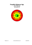
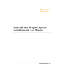
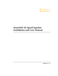
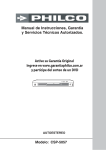
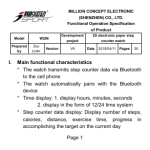
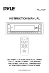
SmartASS-3 Air Speed Speaker
Installation and User Manual
Smart Avionics Ltd.
GND
CANL
CANH
GND
PANEL
UC
IO-1
IO-2
AUDIO
PITOT
+12V
SmartASS-3
STATIC
WWW.SMARTAVIONICS.COM
Revision: 1
www.smartavionics.com
24/07/2014
SmartASS-3 Air Speed Speaker Installation and User Manual
Copyright © 2006-2014 Smart Avionics Ltd.
Table of Contents
1. Introduction ................................................................................................. 1
1.1. Why speak speed? ............................................................................ 1
1.2. Overview of installation .................................................................... 2
1.3. Specifications ................................................................................... 4
1.4. Installing software updates ............................................................. 4
2. Installing the SmartASS-3 .......................................................................... 5
2.1. Setting the configuration switches .................................................. 5
2.1.1. Configuring the speed units .................................................. 6
2.1.2. Configuring the undercarriage alert ...................................... 6
2.1.3. Configuring the general alert ................................................. 6
2.1.4. Firmware upgrade switch ...................................................... 7
2.2. Mounting the enclosure ................................................................... 7
2.3. Mounting the control knob ............................................................... 7
2.4. Pitot and static connections ............................................................ 7
2.5. Electrical connections ...................................................................... 8
2.5.1. Audio connections ................................................................. 8
2.5.2. Alert connections ................................................................... 9
2.5.3. CAN bus connections ............................................................ 9
2.6. Installation approval ......................................................................... 9
3. Using the SmartASS-3 .............................................................................. 11
3.1. The operating modes ..................................................................... 11
3.1.1. Talking ASI mode ................................................................. 11
3.1.2. Speed director mode ........................................................... 11
3.1.3. Sleep mode .......................................................................... 12
3.2. The controls .................................................................................... 12
3.2.1. Push switch primary functions ........................................... 13
3.2.2. Push switch secondary functions ...................................... 14
3.2.3. Push switch summary ......................................................... 15
3.3. Zeroing the SmartASS-3 ................................................................ 15
3.4. Self Test Failure .............................................................................. 16
A. Hacking the SmartASS-3 ......................................................................... 17
A.1. SmartASS-3 Lua files ..................................................................... 17
A.2. Building and flashing eLua ............................................................ 18
B. eLua Open Source License ....................................................................... 19
Index .............................................................................................................. 21
www.smartavionics.com
iii
iv
www.smartavionics.com
List of Figures
1.1. SmartASS-3 Enclosure Panel .................................................................. 2
1.2. Enclosure .................................................................................................. 3
1.3. Control Knob ............................................................................................ 3
1.4. Control Knob Label .................................................................................. 3
2.1. Configuration Switches ........................................................................... 6
www.smartavionics.com
v
vi
www.smartavionics.com
List of Tables
1.1. Specifications ........................................................................................... 4
2.1. Electrical connections ............................................................................. 8
3.1. Push switch functions ........................................................................... 15
www.smartavionics.com
vii
viii
www.smartavionics.com
Chapter 1. Introduction
This manual describes how to install and use the Smart Avionics Air Speed
Speaker Mk3 (hereafter referred to as the “SmartASS-3”). Please read it before
installing and using the SmartASS-3. If you have any questions, please send
email to [email protected] .
1.1. Why speak speed?
The SmartASS-3 has been developed to provide the pilot of a
homebuilt/experimental aircraft with a means of accurately determining their
airspeed without having to look at the airspeed indicator. It does this by
“speaking the speed” in either Knots, MPH or KPH through the intercom/radio
system and hence into the pilot's headset.
It can be used during any phase of flight but it has been specifically developed
for use during the approach phase when both airspeed and flight path need
to be accurately controlled.
During the approach to a short field or if the conditions are challenging, both
speed and flight path are critical. The SmartASS-3 is helpful because:
1. It reduces the amount of time the pilot has to be looking inside the cockpit
so more attention can be paid to getting the flight path right.
2. It supplies the pilot with airspeed information in a form that is easier to
assimilate than by looking at an ASI.
3. It can warn the pilot when the speed has deviated significantly from a
nominated “target speed”.
This last capability (referred to as “speed director mode”) really sets the
SmartASS-3 apart from a conventional ASI. In speed director mode, instead
of simply reporting the current airspeed, the SmartASS-3 will actively monitor
the airspeed, compare it to the target airspeed and then report deviations
from the target speed. The more the airspeed deviates from the target speed,
the more the SmartASS-3 will talk.
Using the SmartASS-3, once the aircraft has been configured for final
approach and the checks have been carried out, the pilot can concentrate on
eyeballing the approach and no longer has to look at the ASI to check the
airspeed every few seconds.
The SmartASS-3 also features:
• A 3-axis accelerometer for measuring the acceleration in the vertical
direction so that the wing loading can be determined – by taking the wing
www.smartavionics.com
1
Overview of installation
loading into account, the speed director becomes a “stall margin preserver”
i.e. it assists the pilot in maintaining a safe speed margin above the stall.
• An optional audible undercarriage alert that will be triggered when the
speed reduces to the approach speed but the undercarriage is not down
and locked.
• An optional audible general alert that can be triggered by any external
system.
Important
Although the SmartASS-3 is accurate and reliable it is intended
that it is used in conjunction with the existing ASI instrument(s)
rather than replacing them.
Important
The SmartASS-3 is not a stall warning system and it does not
provide a stall warning function.
1.2. Overview of installation
Chapter 2 covers the installation of the SmartASS-3 in detail, here we just
give an overview. The SmartASS-3 electronics are contained in a lightweight
aluminium enclosure (Fig 1.2) that may be mounted in any convenient position
and orientation. The enclosure is equipped with two barbed air connectors
for plumbing the unit into the aircraft's pitot and static lines.
PITOT
MICRO
USB
SD 10 WAY CONNECTOR
CARD 1
10
STATIC
Fig 1.1. SmartASS-3 Enclosure Panel
The SmartASS-3's electrical connections are via a removable 10 way screw
terminal connector. A micro SD memory card holds the audio files and some
1
other configuration data .
A combined volume control + push switch (Fig 1.3) that selects the mode of
operation is mounted in any suitable location such that it can be easily
accessed while flying.
1
The micro USB socket is used by Smart Avionics when the unit is being tested and calibrated.
2
www.smartavionics.com
Overview of installation
Fig 1.2. Enclosure
Fig 1.3. Control Knob
SmartASS-3
Turn Knob To
Adjust Volume
Push Knob To
Change Mode
Fig 1.4. Control Knob Label
www.smartavionics.com
3
Specifications
1.3. Specifications
All temperature specifications refer to the temperature of the SmartASS-3
enclosure, not the outside air temperature.
Table 1.1. Specifications
Operating
Temperature
Range
-25°C - 85°C
Minimum Speed 25 Knots / 30 MPH / 50 KPH
Silent below this speed
Maximum Speed 250 Knots / 287 MPH / 462 KPH Not an absolute limit
Absolute
±2%
Accuracy
(linearity & offset)
In the temperature
range 0°C - 85°C.
Assumes unit has been
recently zeroed
Repeatability
(pressure
hysteresis)
±0.1%
At 25°C. For speeds
between 25 and 250
Knots
Supply Voltage
6-18V
Reverse polarity
protected
Supply Current
100 mA
Audio Output
Voltage
3V Peak
Minimum Load
Impedance
50 Ohms
Electrical
Connector
10 Way plug/socket
Screw terminals
Air Connectors
Hose barbs
Requires 4mm ID tubing
Enclosure
Dimensions
140 x 86 x 30 mm
Includes mounting tabs
Total Weight
230 grams
With 200 Ohm load
1.4. Installing software updates
Software updates are installed simply by copying the updated file(s) into the
top-level (root) directory of the SD card. This can be done on any system
(Linux, Mac, Windows, etc.) that supports SD card storage (either directly or
via a USB adapter). Please ensure the power is off before ejecting or inserting
the SD card and that the card is fully home before applying power again.
4
www.smartavionics.com
Chapter 2. Installing the SmartASS-3
Installation of the SmartASS-3 consists of the following steps:
1. Setting the configuration switches (if necessary).
2. Mounting the enclosure within the instrument panel.
3. Mounting the control knob on the instrument panel.
4. Connecting the pitot and static connections.
5. Connecting the power supply and audio output wires and, optionally, the
undercarriage and general alert wires.
6. Carry out a one-time initialisation procedure that orientates the
accelerometer (described in Section 3.2.2.2).
2.1. Setting the configuration switches
If you wish to change the speed units from the default setting of Knots or
enable the undercarriage or general alert functions, you will need to access
the configuration switches on the circuit board. To gain access to the board,
remove the 10 way connector and the SD card, and then remove the four
screws and the front plate and slide the board out.
Four switches are located together in one block on the left side of the PCB.
One other switch is located about 3cm away (4 o'clock position) from the
block of 4. All the switches have yellow tops and a small arrow that shows
the direction the switch must be moved to turn it on. Use the end of a small
screwdriver or pencil to move the switch and make sure that the other
switches are not moved also (it's rather easy to do that). Fig 2.1 shows the
layout of the switches in their default positions (all off).
After the switches have been configured, slide the PCB back into the case
and replace the front plate and screws. Reinsert the SD card and 10 way
connector.
Important
The circuit board contains components that may be damaged by
static electricity. Try to avoid touching the components on the
board and, if possible, remove any static charge that you may be
carrying by touching something that is earthed before handling the
unit.
www.smartavionics.com
5
GA
UCA
KPH
MPH
ON ON ON ON
Configuring the speed units
FIRMWARE
UPGRADE
(OFF)
ON
Fig 2.1. Configuration Switches
2.1.1. Configuring the speed units
By default, the SmartASS-3 reports the airspeed in Knots. If desired, the
airspeed can be reported in either MPH or KPH by closing the appropriate
switch. Slide the switch to the on position to select the required speed unit.
2.1.2. Configuring the undercarriage alert
If you want to use the undercarriage alert feature, move the UCA switch to
the on position.
If you have a retractable undercarriage, you can enable this alert even if you
don't have a switch that signals when the undercarriage is down and locked.
In that case, whenever speed director mode is entered, the undercarriage
alert will be triggered to remind you to check that the wheels are down. Once
the alert has sounded, briefly press the push switch to cancel the alert.
If you do have the undercarriage down switch, the alert will be suppressed if
the undercarriage is down when speed director mode is entered.
2.1.3. Configuring the general alert
If you want to use the general alert feature, move the GA switch to the on
position.
When enabled, the general alert will be triggered by a low level on the general
alert input (IO-1). Once the alert has sounded, briefly press the push switch
to cancel the alert.
6
www.smartavionics.com
Firmware upgrade switch
2.1.4. Firmware upgrade switch
This switch is turned on to enable the firmware to be upgraded via the micro
USB connector. In normal operation, this switch must be off.
2.2. Mounting the enclosure
The enclosure can be mounted in any convenient position and orientation
within the instrument panel area. If possible, mount close to the centreline
of the aircraft to minimise the effect of roll on the accelerometer readings
(this isn't absolutely essential). Remember to leave adequate space so that
the pitot and static lines are not kinked.
Although the SmartASS-3 is robust, avoid subjecting it to excessive vibration
or extremes of temperature.
Important
Take care to ensure that the SD card is fully home in its socket as
it is quite easy to “eject” the card by mistake.
2.3. Mounting the control knob
The control knob should be mounted in a position such that it can easily be
operated while flying. The hole required is 10.2mm diameter with 8.3mm flats
to stop the potentiometer body from turning. The potentiometer manufacturer's
recommended torque for tightening the retaining nut is 45cN.m
If the wires from the control knob to the enclosure are too long, they may
either be shortened or coiled up.
2.4. Pitot and static connections
The SmartASS-3's pressure sensor has barbed connections suitable for 4
mm ID hose. Exactly how the pitot and static connections are plumbed into
the aircraft's pitot and static lines will be different for each aircraft but,
generally speaking, tee connectors can be inserted into the existing lines so
that the SmartASS-3 is connected in parallel with the existing ASI. Take care
to ensure that all the connections are sound and that no leaks are present.
Important
Once the installation is completed, carry out a leak test on the pitot
and static lines to ensure that no leaks have been introduced.
www.smartavionics.com
7
Electrical connections
2.5. Electrical connections
All the electrical connections are made through the 10 way connector. Make
sure that the wires are securely held in the connector terminals. Use cable-ties
or lacing cord to bundle the wires near the connector. This will reduce the
chance of the wires coming loose in the connector or fracturing due to flexing.
Table 2.1. Electrical connections
Terminal
Name
Connection
1
GND
Radio/intercom ground
2
CANL
CAN bus low
3
CANH
CAN bus high
4
GND
Control knob (either connection)
5
PANEL
Control knob (either connection)
6
UC
Switch to ground when U/C down and
locked
7
IO-1
Input/Output #1 - switch to ground
to signal general alert
8
IO-2
Input/Output #2
9
AUDIO
Audio output to radio/intercom input
10
+12V
Fused 12V supply
2.5.1. Audio connections
For audio output, these wires need to be connected:
8
GND (terminal 1)
This is connected to the main ground bus-bar or
a ground associated with the radio or intercom.
GND & PANEL (4 & 5)
These connections are to the two wires from the
control knob.
AUDIO (terminal 9)
This is connected to an auxiliary or music input
of the aircraft's existing radio/intercom/audio
panel installation. Exactly where this should be
connected obviously depends on the specific
equipment being connected to.
+12V (terminal 10)
This is connected to +12V via a fuse or circuit
breaker. The current requirement of the
SmartASS-3 is small so the fuse rating need not
be more than 1A. The SmartASS-3 does not have
an on/off switch as it doesn't really need one but,
if you wish, you could put a switch into this line.
www.smartavionics.com
Alert connections
Note
Intercoms and radios often have the ability to mute the auxiliary
input when radio transmissions are being received. It is up to you
to decide whether to mute the output from the SmartASS-3 or not.
Note
If the volume of the SmartASS-3's output is not well matched to
the sensitivity of the existing equipment's input and that equipment
has no means of adjusting its sensitivity, please contact Smart
Avionics for advice.
2.5.2. Alert connections
If you wish to use the audio alerts, two more wires can be connected:
UC (terminal 6)
If you want to use the undercarriage warning facility,
install a switch that connects this terminal to ground
when the undercarriage is down and locked. When
the undercarriage alert is activated, you will hear:
“DING! Check wheels down, ...”. Pressing the push
switch briefly or putting the undercarriage down will
silence the alert. Remember to enable this feature
by setting the appropriate configuration switch as
described on Section 2.1.2.
IO-1 (terminal 7)
Switching this terminal to ground will trigger the
general audible alert. When the general alert is
activated, you will hear: “DING! Alert, ...”. Pressing
the push switch briefly will silence the alert.
Remember to enable this feature by setting the
appropriate configuration switch as described on
Section 2.1.3.
2.5.3. CAN bus connections
The SmartASS-3 transmits airspeed and acceleration (vertical G) data on the
CAN bus (terminals 2 and 3). The data rate is 250K bits/S and the messages
are in CAN Aerospace format. Please contact Smart Avionics for more details
if you wish to make use of this data.
2.6. Installation approval
Before the aircraft can be flown with the SmartASS-3 installed, the installation
has to be approved. Exactly how this is achieved differs from country to
country.
www.smartavionics.com
9
Installation approval
In the UK, the installation must be inspected and approved by your LAA
inspector and an entry made in the airframe log book. The LAA will need to
be informed that the SmartASS-3 has been fitted.
10
www.smartavionics.com
Chapter 3. Using the SmartASS-3
3.1. The operating modes
The SmartASS has three modes of operation: “talking ASI”, “speed director”
and “sleep”.
3.1.1. Talking ASI mode
This mode simply speaks the current airspeed every few seconds. The repeat
period can be 3, 6 or 12 seconds. Also, if the speed changes very rapidly, the
new speed is spoken straight away.
When the speed is less than 25 Knots (30 MPH, 50 KPH) the voice is muted.
When the SmartASS-3 is powered up, it always starts in talking ASI mode.
3.1.2. Speed director mode
In this mode, the airspeed is continuously measured and compared to a target
speed. The SmartASS-3 reports as follows:
• If the speed is within 5% of the target speed, it says “Speed good” every 8
seconds
• If the speed is between 5% and 10% too fast, it says “Fast” every 4 seconds.
• If the speed is between 5% and 10% too slow, it says “Slow” every 4
seconds.
• If the speed is between 10% and 15% too fast, it says “Very fast” every 2
seconds.
• If the speed is between 10% and 15% too slow, it says “Very slow” every 2
seconds.
• If the speed is more than 15% too slow or too fast, the appropriate message
is prefixed with a chime.
As the wing loading increases, the SmartASS-3 estimates how much this will
increase the stall speed and it subtracts that amount from the current
airspeed. If the pilot “pulls G”, the SmartASS-3 will immediately report that
the aircraft is slow even though the actual airspeed has not (yet) changed.
Unloading the wing will immediately make the SmartASS-3 report a speed
1
increase .
1
The SmartASS-3 ignores reduced G (less than +1) so it will not be fooled into telling you that you are fast
if you move the stick forward rapidly.
www.smartavionics.com
11
Sleep mode
If the speed drops to below 80% of the target speed or is above 125% of the
target speed, the SmartASS-3 reverts to talking ASI mode.
Speed director mode is entered automatically when the speed falls to within
5% of the target speed.
In speed director mode, the volume of the voice will automatically reduce the
longer you stay within a given speed band. So if the air is smooth and you
are flying accurately, the “Speed good” messages will become quieter and
quieter as you progress towards the runway threshold. If the speed strays
into another speed band, the volume immediately increases back to the
original level.
Tip
• Always trim the aircraft accurately for the chosen approach
speed.
• Try not to “chase” the airspeed, especially when the air is rough.
• Aim to smoothly increase or decrease the speed to keep the
“speed good”.
• The airspeed cannot change instantly, it takes a few moments
for a change in attitude or power to have an effect on the airspeed
and a bit longer for the SmartASS-3 (and your mechanical ASI)
to measure that speed.
3.1.3. Sleep mode
In this mode, the SmartASS-3 doesn't say anything at all. It doesn't even
snore! Sleep mode continues until:
• The pilot briefly presses the push switch to enable talking ASI mode.
Typically, this could occur downwind in the circuit as the pilot prepares for
the approach and landing.
• The airspeed reduces to within 5% of the target speed and the SmartASS-3
automatically wakes up in speed director mode.
• The general alert is triggered.
3.2. The controls
The SmartASS-3 has been designed to be very easy to use. A combined
volume control and push switch is all that is required.
12
www.smartavionics.com
Push switch primary functions
The volume control works in the conventional manner: turning the volume
control clockwise increases the volume of the speech. Turning the volume
control anti-clockwise reduces the volume.
2
When power is applied to the SmartASS-3, it says “Airspeed in Knots” and
then, if the unit auto-zeroes itself, it will say “Airspeed zeroed”. Section 3.3
has more information about zeroing.
If the unit has not yet been orientated, it will also say “G disabled”.
Section 3.2.2.2 describes how the unit is orientated.
Important
If when the SmartASS-3 is switched on, the airspeed is at least 25
Knots (30 MPH, 50 KPH), the voice will say “Compare to ASI” after
the speed is first reported. This is to remind the pilot to check that
the spoken speed is consistent with the speed indicated on the
ASI. If the speeds tally, the SmartASS-3 can be considered
trustworthy. If there is a significant difference between the spoken
speed and the speed shown on the ASI, the SmartASS should not
be used until the discrepancy has been investigated.
3.2.1. Push switch primary functions
The push switch has three primary functions:
3.2.1.1. Silencing an alert message
If either of the undercarriage or general alerts sound, they can be silenced by
3
pressing the push switch briefly .
3.2.1.2. Selecting the operating mode
Pressing the push switch briefly, toggles the mode of operation between
talking ASI mode and either speed director or sleep modes. When in talking
ASI mode, if the airspeed is no more than 125% of the target speed, pressing
the push switch briefly will change to speed director mode. Otherwise, sleep
mode is entered. Irrespective of the current airspeed, pressing the push switch
briefly twice in quick succession will always enter sleep mode. Pressing the
push switch briefly when in either speed director or sleep modes will change
to talking ASI mode.
The mode change is announced as follows:
Talking ASI mode is selected
The SmartASS-3 says “Airspeed” and then
starts to speak the airspeed.
2
Or MPH or KPH depending on the units selected during installation.
When you press the push switch briefly, you don't hear any audio feedback (no beep).
3
www.smartavionics.com
13
Push switch secondary functions
Speed director mode is selected
The SmartASS-3 announces the
(previously captured) target airspeed by
saying “Target speed is ...”. Listen to the
number it says and confirm that is the
speed you want. If the number it says is
not what you want, you will need to
capture a new airspeed as described
below.
Sleep mode is selected
The SmartASS-3 says “Goodbye” and then
goes silent.
Note
Until an airspeed has been captured, the SmartASS-3 will not select
speed director mode.
3.2.1.3. Capturing the target airspeed
Pressing the push switch for more than 1/2 second “captures” the current
airspeed and switches to speed director mode if that mode is not already
active. An audio “beep” sounds after the switch has been pressed for enough
time to capture the airspeed. The new target airspeed will be announced as
“Target speed is ...” and will be stored until another speed is captured. The
target airspeed is remembered when the power is off.
3.2.2. Push switch secondary functions
The push switch also has these secondary functions:
3.2.2.1. Selecting the airspeed repeat rate
By default, the airspeed is repeated every 6 seconds in talking ASI mode. This
period can be altered by pressing and holding the push switch until two beeps
are heard. This will cycle the airspeed repeat period between the values of 3,
6 and 12 seconds. When the switch is released, you should hear the message
“Repeat period is ...”. The selected value is remembered when the power is
off.
3.2.2.2. Orientating the accelerometer
Once the SmartASS-3 has been installed, the unit must be orientated so that
it knows which way is up. With the aircraft positioned in the flying attitude,
press and hold the push switch until three beeps are heard. When the switch
is released you should hear the message “Orientation set”. The orientation
is remembered when the power is off and this operation only needs to be
repeated if the SmartASS-3 is re-positioned.
14
www.smartavionics.com
Push switch summary
This orientation operation can be carried out in flight – just take care to ensure
that the aircraft is flying straight and level and that you are not subject to any
vertical accelerations at the time.
3.2.2.3. Zeroing the pressure sensor
Press and hold the push switch until you have heard the fourth beep. When
the switch is released, the SmartASS-3 will say “Airspeed zeroed”.
3.2.3. Push switch summary
This table summarises the operation of the push switch:
Table 3.1. Push switch functions
Action
Effect
1 short press
Silence alert
1 short press
Toggle between talking ASI and speed
director or sleep modes
2 short presses
Enter sleep mode
Hold for 1 beep
Capture current airspeed and enter speed
director mode
Hold for 2 beeps
Cycle through airspeed repeat periods
Hold for 3 beeps
Orientate accelerometer
Hold for 4 beeps
Zero pressure sensor
3.3. Zeroing the SmartASS-3
To ensure the airspeed reported by the SmartASS-3 is as accurate as possible,
the unit requires zeroing occasionally. This will remove any offset error
4
introduced as the pressure sensor and the electronic components age.
Whenever the SmartASS-3 is turned on, as long as the current differential
pressure is small, it will be zeroed automatically to remove the offset error.
If the differential pressure is not small when the unit is turned on, this
auto-zeroing will not occur and you will hear “DING! airspeed not zeroed”.
It is possible to manually zero the SmartASS-3 at any time. There are two
ways of achieving this:
1. Apply power to the unit while already pressing the push switch. When the
voice says “Airspeed zeroed”, release the push switch.
4
Due to the fact that airspeed is proportional to the square root of the dynamic pressure, the effect of a small
offset error in the pressure measurement is only really significant at very low airspeeds. It's still worth
removing the error to get the best possible result.
www.smartavionics.com
15
Self Test Failure
2. With the SmartASS-3 already turned on, press and hold the push switch
until you have heard the 4th beep and then release the switch. The
SmartASS-3 will then say “Airspeed zeroed”.
Important
To ensure that the reported speed is accurate, do not manually
zero the SmartASS-3 if any of the following are true:
• The aircraft is moving at more than walking pace.
• The wind is blowing into the pitot and it is more than a very gentle
breeze.
• The pitot cover is in position.
• The temperature of the SmartASS-3 unit is below 0°C or above
40°C.
3.4. Self Test Failure
When the SmartASS-3 is turned on, it carries out a sequence of tests to check
that it is functioning correctly. If any of the tests fail, the SmartASS-3 goes
into a loop, continuously reporting the failure through the audio interface.
The failure is reported as “DING! Fail number” where number is the error code
for the particular test that has failed. However, if the voice data cannot be
accessed, the failure message can't be played and so, instead, the error is
5
signalled by bursts of random noise . In either case, please switch off the
SmartASS-3 and contact Smart Avionics to resolve the problem.
5
Sounds a bit like the radio when a very weak transmission is received.
16
www.smartavionics.com
Appendix A. Hacking the SmartASS-3
Note
You don't have to read this Appendix to install and use the standard
SmartASS-3. It's here to give some guidance to people who want
to modify the SmartASS-3's behaviour.
The SmartASS-3 program is written in the Lua scripting language (see
www.lua.org. Lua is a widely used interpreted language that has been around
for more than 20 years. The implementation used here is the eLua (embedded
Lua) system (see www.eluaproject.net). Appendix B shows the eLua license.
The SmartASS-3 source code is freely available as a git repository and can
be found at https://bitbucket.org/smartavionics/elua-smartass. The
SmartASS-3 specific files all reside in the smartass-master branch (and
associated development branch, smartass-dev). These branches are based
on the master branch which is synced with the upstream eLua repository.
You can access the eLua console by connecting the SmartASS-3 USB socket
to a PC and running a terminal emulator program. On Linux systems (or
similar), screen /dev/ttyACM0 115200 will connect you to the console
and you can see debug output. For Windows systems, various terminal
emulator programs exist. PuTTY is freely available and works OK.
A.1. SmartASS-3 Lua files
The smartass directory contains these Lua script files:
ad7798.lua
Driver for the AD7798 ADC used to measure the pitot
pressure.
autorun.lua
Startup script that is run when the device is powered up.
It loads the smartass module and starts executing it.
lis3dh.lua
Driver for the LIS3DH accelerometer.
smartass.lua
The smartass module, this is where it all happens!
wav.lua
A very simple module for playing WAV audio files. This
only copes with uncompressed 8 or 16 bit PCM data.
You do not need to build and flash eLua when just these script files are
modified. So if you change them, simply copy the changed files into the root
directory of the SmartASS's SD card and they will be used instead of the
original files. If you subsequently remove your files from the SD card, the
originals will be used again. Take care not to remove any of the other files on
the SD card.
www.smartavionics.com
17
Building and flashing eLua
A.2. Building and flashing eLua
Note
SmartASS-3 development is done using Linux host computers.
However, it should be possible to build and flash eLua using
non-Linux hosts as all of the tools used are available for other
systems.
To rebuild the underlying eLua system you need to install an ARM cross
compilation system that provides arm-none-eabi-gcc and its companions.
You can obtain these from https://launchpad.net/gcc-arm-embedded.
A Makefile is provided that defines targets to build the eLua system and flash
(download) it to the board. The board supports two methods of flashing:
SWD
Using a SWD adapter such as a STLINK-V2 attached to PL3,
utilities such as openocd can be used to flash and debug the
program. The PL3 connections are:
1. +3V3 (pin 1 is nearest to the SD card)
2. SWCLK
3. GND
4. SWDIO
While flashing the program, you can either power the board via
the 10 way connector or through the USB connector (by
connecting a USB cable to a PC or a USB power adapter). This
method of programming is a little faster than the DFU method
and also gives you the ability to debug the C code using gdb.
DFU
18
Utilities such as dfu-util can flash the program via the USB cable.
To do this, the switch PL4 needs to be in the on position before
power is applied to the board. The USB cable will power the
board while it is being flashed so you don't need the 10 way
connector plugged in. Remember to move PL4 back to the off
position after the download has finished. The advantage of this
method is that you only need a USB cable and no programming
adapter.
www.smartavionics.com
Appendix B. eLua Open Source License
Copyright (c) 2007, 2008, 2009, 2010, 2011 Dado Sutter and Bogdan Marinescu
eLua is Open Source and is freely distributed under the MIT licence.
The Lua part of eLua is licensed under the Lua licensing terms, which you
can find at http://www.lua.org/license.html.
The XMODEM code is adapted from the FreeBSD at91 library, which was written
by M. Warner Losh and is released under the BSD license.
The "pack" module is adapted from the "lpack" module by Luiz Henrique de
Figueiredo and it's placed in the public domain.
The "bit" module is adapted from the "bitlib" library by Reuben Thomas,
distributed under a MIT license.
The "integer only lua" is based on the "Go Long Lua!" patch by John D.
Ramsdell (from the Lua Power Patches page) and is placed in the public
domain.
The multiple memory allocator (dlmalloc) is written by Doug Lea and is
placed on the public domain.
The TCP/IP stack is adapted from uIP, written by Adam Dunkels and released
under a BSD license.
The FAT file sistem is based on FatFs, written by Elm Chan (http://elm-chan.org).
A copy of the FatFs license can be found in the LICENSE.fatfs file.
The RPC implementation is based on Russell Smith's Lua-RPC
(http://q12.org/lua/index.html).
A copy of the Lua-RPC license can be found in the LICENSE.luarpc file.
Manufacturer provided CPU support libraries are licensed under their own
terms, check src/platform/*platform-name* for details.
linenoise (https://github.com/antirez/linenoise, eLua's readline replacement)
is released under a BSD license.
The rest of the eLua code is licensed under MIT, listed below:
The MIT License
Copyright (c) 2007, 2008, 2009, 2010 Dado Sutter and Bogdan Marinescu
www.smartavionics.com
19
Permission is hereby granted, free of charge, to any person obtaining a copy
of this software and associated documentation files (the "Software"), to
deal in the Software without restriction, including without limitation the rights
to use, copy, modify, merge, publish, distribute, sublicense, and/or sell
copies of the Software, and to permit persons to whom the Software is
furnished to do so, subject to the following conditions:
The above copyright notice and this permission notice shall be included in
all copies or substantial portions of the Software.
THE SOFTWARE IS PROVIDED "AS IS", WITHOUT WARRANTY OF ANY KIND,
EXPRESS OR IMPLIED, INCLUDING BUT NOT LIMITED TO THE WARRANTIES OF
MERCHANTABILITY, FITNESS FOR A PARTICULAR PURPOSE AND
NONINFRINGEMENT.
IN NO EVENT SHALL THE AUTHORS OR COPYRIGHT HOLDERS BE LIABLE
FOR ANY CLAIM, DAMAGES OR OTHER LIABILITY, WHETHER IN AN ACTION
OF CONTRACT, TORT OR OTHERWISE, ARISING FROM, OUT OF OR IN
CONNECTION WITH THE SOFTWARE OR THE USE OR OTHER DEALINGS IN
THE SOFTWARE.
20
www.smartavionics.com
Index
KPH, 6
M
A
accelerometer
orientation, 14
airspeed
capturing, 14
repeat rate, 14
alert, 9
general, 6
undercarriage, 6
C
CAN bus, 9
capturing airspeed, 14
check wheels down, 9
configuring
general alert, 6
speed units, 6
undercarriage alert, 6
connections
electrical, 8
pitot and static, 7
control knob
mounting, 7
E
electrical connections, 8
enclosure
mounting, 7
modes of operation, 11
MPH, 6
mute
audio input, 9
O
operating modes, 11
orientation, 14
P
pitot connection, 7
push switch, 12-13
S
SD card, 2
self test failure, 16
software updates
installing, 4
specifications, 4
speed director mode, 1, 11
static connection, 7
static electricity warning, 5
switch
configuration, 5
T
talking ASI mode, 11
U
F
Fail message, 16
firmware upgrade
switch, 7
G
G disabled, 13
general alert
wiring, 9
undercarriage warning
wiring, 9
V
volume control, 12
Z
zeroing, 15
I
installation
approval, 9
K
Knots, 6
www.smartavionics.com
21
22
www.smartavionics.com