1
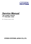
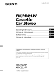
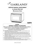
FILE NO.
SERVICE MANUAL
Microwave Oven
EM-C2001UK
EM-C2001SD
Model No
EM-C2001SD
EM-C2001UK
Pro.Code No
437 508 00
437 508 01
Foreword
Read this manual carefully, especially precaution on microwave energy, and follow the procedure strictly,
careless servicing and testing may expose yourself to the microwave energy leakage.
PRECAUTIONS
PRECAUTIONS TO BE OBSERVED BEFORE AND DURING SERVICING TO AVOID POSSIBLE EXPOSURE TO
EXCESSIVE MICROWAVE ENERGY
(a) Do not operate or allow the oven to be operated with the door open.
(b) Make the following safety checks on all ovens to be serviced before activating the magnetron or other
microwave source, and make repairs as necessary:
(1)Interlock operation, (2) proper door closing, (3) seal and sealing surfaces (arcing, wear, and other
damage), (4) damage to or loosening of hinges and latches, (5) evidence of dropping or abuse.
(c) Before turning on microwave power for any service test or inspection within the microwave generating
compartments, check the magnetron, wave guide or transmission line, and cavity for proper alignment,
integrity, and connections.
(d) Any defective or misadjusted components in the interlock, monitor, door seal, and microwave generation
and transmission systems shall be repaired replaced, or adjusted by procedures described in this manual
before the oven is released to the owner.
REFERENCE NO. SM-6410003-00
- TABLE OF CONTENTS Adjustment Procedures ............................................. 1
Specifications ............................................................ 2
Power output Measurement ...................................... 2
Precautions and Repair Service Tips ....................... 2
Circuit Diagram ......................................................... 3
Test Procedures and Troubleshooting............... 4-10
Disassembly Instructions............................. 11-15
Exploded View and Parts List1........................16-22
Overall Circuit Diagram................................. 23-25
up and rotated counterclockwise until there is zero
gap between the latch lever and the switch bodies
when the door latch is securely locked.
(4) Make sure the latch interlock switch open before
the interlock monitor switches coses when the door
is opened very slowly, according to “CHECKOUT
PROCEDURE FOR SWITCHES” on page 6.
(5)Make sure the microwave energy leakage is below
the limit of the reguration 5 mW/cm 2when
measured with a detector.
(All service adjustments must be made for minimum microwave energy leakage readings.)
NOTE: If the interlock monitor circuit operates and at
the same time the fuse blows with the door
open, be sure to replace the relay circuit board
, Interlock switch and monitor switch.
CAUTION
MICROWAVE RADIATION
PERSONNEL SHOULD NOT BE EXPOSED TO
THE MICROWAVE ENERGY WHICH MAY RADIATE FROM THE MAGNETRON OR OTHER
MICROWAVE GENERATING DEVICE IF IT IS
IMPROPERLY USED OR CONNECTED. ALL
INPUT AND OUTPUT MICROWAVE CONNECTIONS, WAVEGUIDE, FLANGES, AND GASKETS
MUST BE SECURE. NEVER OPERATE THE
DEVICE WITHOUT A MICROWAVE ENERGY
ABSORBING LOARD ATTACHED. NEVER LOOK
AN OPEN WAVEGUIDE OR ANTENNA WHIL THE
DEVICE IS ENERGIZED.
1. ADJUSTMENT PROCEDURES
TO AVOID POSSIBLE EXPOSURE TO MICROWAVE
ENERGY LEAKAGE, THE FOLLOWING ADJUSTMENTS OF THE INTERLOCK SWITCHES SHOULD
BE MADE ONLY BY AUTHORIZED SERVICE PERSONNEL.
Latch Lever
Interlock
monitor switch
A.INTERLOCK SWITCH AND DOOR SENSING
SWITCH ADJUSTMENT(Figure 1-a)
(1) Loosen 2 screws securing the lever stopper.
(2) Adjust the lever stopper position so that it is pushed
up and rotated counterclockwise until there is zero
gap between the latch lever and the switch bodies
when the door latch is securely locked.
(3) Tighten the lever stopper screws securely.
(4) Make sure the latch interlock switch and the door
sensing switch open before the interlock monitor
switches coses when the door is opened very
slowly, according to “CHECKOUT PROCEDURE
FOR SWITCHES” on page 6.
(5)Make sure the microwave energy leakage is below
the limit of the reguration5 mW/cm 2when
measured with a detector.
(All service adjustments must be made for minimum microwave energy leakage readings.)
Door sensing
switch
Figure 1-a
Latch Lever
Latch Interlock
switch
(Screws)
Figure 1-b
B.LATCH INTERLOCK SWITCHES ADJUSTMENT
(Figure 1-b)
(1) Loosen 2 screws securing the lever stopper.
(2) Adjust the lever stopper position so that it is pushed
- 1 -
2.SPECIFICATIONS
A. SINCE NEARLY 4,000 VOLTS EXISTS IN SOME
CIRCUITS OF THIS MICROWAVE OVEN, REPAIRS SHOULD BE CARRIED OUT WITH
GREAT CARE.
B. TO AVOID POSSIBLE EXPOSURE TO MICROWAVE ENERGY LEAKAGE, THE FOLLOWING
PRECATIONS MUST BE TAKEN BEFORE SERVICING.
(1) Before the power is applied.
(a) Open and close door several times to make
sure the interlock switch, door sensing switch
and interlock monitor switch operate properly.
(Listen for the clicking sound from switches.)
Make sure the interlock monitor switch is
closed after the interlock switch and door sensing are open when the door is opened.
(See pages 1 and 6)
(b) Make sure the perforated screen and the choke
dielectric of the door are correctly mounted.
(2) After the power is applied.
(a) Open and close the door to see if the interlock
mechanism operates properly.
(b) Check microwave energy leakage with a leakage detector and confirm the energy leakage
is below 5mW/cm2
(3) Do not operate the unit until it is completely
repaired of any of the following conditions.
(a) Door is not closed firmly against the cavity
front.
(b) The hinge is broken.
(c) The choke dielectric or the door seal is damaged.
(d) The door is bent or warped, or there is any
other visible damage to the oven that may
cause microwave energy leakage.
Note: Always keep the seal clean.
(e) Make sure that there are no defective parts in
the interlock mechanism.
(f) Make sure that there are no defective parts in
the microwave generating and transmission
assembly. (especially wave guide).
(4) The following items should be checked after
the unit is repaired.
(a) The interlock monitor switch is connected correctly and firmly.
(b) The magnetron gasket on the magnetron is
properly positioned.
(c) Waveguide and oven cavity are intact. (No
leakage of microwave energy).
(d) The door can be properly closed and the safety
switches work properly.
(e) The oven must be stopped when the door is
opened or the time is up.
The oven must not be operated with any of the above
components removed or bypassed.
Microwave output ................ 1,900W,950W,190W
Frequency ........................... 2,450MHz
Power supply ....................... 220-230V, 50Hz
Rated current ...................... 13 Amp.
Safety Device ......................
Thermal protector(Magnetron) 150°C Open
(Cavity)
122°C Open
Thermistor (Magnetron)
200°C Open
Thermistor(Duct)................120°C Open
Fuse (Cartridge Type) ................. 250V 10A
Micro switch, Safty Relay
Interlock Switch
Interlock monitor Switch
Door sensing Switch and
SaftyRelay
Max. input time .................... Electronic Digital, up to
Manual 10min./Memory 30min.
Overall Dimensions ........ 422(W)x540(D)x335(H) mm
Oven cavity size ............ 330(W)x330(D)x230(H) mm
Effective Capacity of Oven Cavity.........19.1liters
Net weight ........................... 32Kg
3. POWER OUTPUT MEASUREMENT
(1) Prepare 1000±5cc tap water.
(2) Adjust water temperature to 10 ±2°C.
(3) Pour the water into a container made of borosilicate glass, 190mm outer diameter cylinder, maximum 3 mm thickness.
NOTE: Use the container kept on the room
temperature.
(4)Place the container in the center of the oven cavity.
(5) Set the heating time for 25 seconds and rating
full power and then start oven.
(6) Take container out immediately when heating time
up.
(7) Stir water for making even water temperature in
the container.
(8) Measure the water temperature.
Water temperature rise shall be 8°C to 12°C.
(9) For correct Power output measurement, the line
voltage under load must be 230±2Volts.
4.PRECATIONS AND REPAIR SERVICE TIPS
PRELIMINARY
- 2 -
5.CIRCUIT DIAGRAM
Figure 3
* Caution: The voltage between filament leads of magnetron is about 3.3VA.C, but the filament carries
4KV/DC high voltage with respect to ground.Never touch these leads with bare hand during operation.
- 3 -
6. TEST PROCEDURES AND TROUBLESHOOTING
PRIMARY
CAUTION
WINDINGS
-DISCONNECT THE POWER SUPPLY CORD FROM THE WALL
OUTLET WHENEVER REMOVING THE CABINET FROM THE UNIT.
PROCEED WITH TESTS ONLY AFTER DISCHARGING THE HIGH
VOLTAGE CAPACITORS AND REMOVING THE LEAD WIRES ON
THE PRIMARY WINDING OF THE HIGH VOLTAGE TRANSFORMERS FOR LOWER AND UPPER MAGNETRONS.
Filament
Windings
(SEE FIGURE 3)
A. TEST PROCEDURES
COMPONENT
MAGNETRON
Secondary
Windings
Figure 3
CHECKOUT PROCEDURE
RESULT
1) Check for resistance: Across the filament terminal of the magnetron with an ohm - meter
on Rx1 scale.
Normal reading:
Less than 1 ohm.
Figure 4
2) Check for resistance: Between each filament
terminal of the magnetron and the chassis
ground with an ohm-meter on highest scale.
Normal reading:
Infinite ohms.
Figure 5
HIGH-VOLTAGE
TRANSFORMER
1) Measure the resistance:
With an ohm-meter on R x1 scale.
a. Primary winding;
b. Filament winding;
c. Secondary winding;
2) Measure the resistance:
with an ohm-meter on highest scale.
a. Primary winding to ground;
b. Filament winding to ground;
Figure 6
- 4 -
Normal reading:
Approximately 1.0 ohms
Less than 1 ohm.
Approximately 60 ohms
Normal reading:
Infinite ohms.
Infinite ohms.
Note: Remove varnish of measured point.
COMPONENT
HIGH-VOLTAGE
CAPACITOR
Including internal
bleeder
resistor
CHECKOUT PROCEDURE
RESULT
Measure the resistance: Across two terminals with
an ohm-meter on highest scale.
Normal reading:
Momentarily indicates several ohms, and
gradually to 10 meg-ohms.
Abnormal reading:
Indicates continuity or 10 meg-ohms
from the beginning.
Figure 7
HIGH-VOLTAGE
DIODE
Measure the resistance: Across two terminals with
an ohm-meter on highest scale.
Figure 8
Measure the resistance: Across two terminals
with an ohm-meter on highest scale.
Normal reading:
Indicate about middle position in one
direction (forward) and infinite ohms in
the reverse direction, using ohm meter
with a 9V battery.
NOTE
- Some digital meter may show more
than 0 ohms or infinite ohms even in a
forward direction because the low measuring voltage of the meter does not
allow the meter to pass through the high
voltage diode. Use an ohm meter with
a 9V battery.
Abnormal reading:
Indicates continuity or infinite ohms in
both directions.
Normal reading:
Indicate infinite ohms in both directions.
FUSE DIODE
Figure 9
- 5 -
Abnormal reading:
Indicates continuity in both directions
or continuity in one direction and
infinite ohms in reversed direction.
COMPONENT
TOUCH KEY
BOARD
CHECKOUT PROCEDURE
Measure the resistance between terminals of
FPC connector after removing it from
S101.(Figure 10)
NOTE
- When reconnecting the FPC connector, make
sure the holes on the connector are properly
inserted in hook of the plastic fastener in S101.
RESULT
When
Resistance touched
Value
Less than
1 K ohms
When not
touched
More than
1 meg ohms
When checking the
key ,
connect the ohm-meter as illustrated
below.
MATRIX CIRCUIT FOR
TOUCH KEY BOARD
FPC CONNECTOR
TERMINAL OF FPC CONNECTOR
FIGURE 10
CHECKOUT PROCEDURE FOR SWITCHES
Disconnect the lead wires from the switches and check for the continuity of the switches, connecting an ohm-meter
to its terminals.
SWITCHES
(SEE Figure 1 on page 1)
CHECKOUT PROCEDURES
DOOR OPEN
DOOR CLOSED
INTERLOCK SWITCH
Terminals "COM" and "NO"
DOOR SENSING SWITCH
INTERLOCK MONITOR
SWITCH
Terminals "COM" and "NC"
CAUTION: After checking the switches, make sure that the interlock monitor switch is properly connected according
to the CIRCUIT DIAGRAM on page 3.
- 6 -
WARNING:
Primary
When removing the cabinet, you must disconnect Winding
the power supply cord from the wall oulet for your
safety. Only the checkout procedure below needs
the power supply on. TAKE GREAT CARE to avoid
possible electrical shock.
For your safety, proceed with the test only
after removing the wire leads from the primary winding of the high voltage transformer
Primary
Winding
Lower
Upper
COMPONENT
CHECKOUT PROCEDURE
RESULT
CONTROL
CIRCUIT BOARD
Measur the voltage : Between test points
TP-1, TP-2, TP-3 and ground or between
TP-4 and Tp-5(See figure 16 on page 27).
CAUTION:
For your safety, proceed with the test only
after removing the wire leads from the primary winding of high voltage transformer.
NOTE
- Proceed with the check of the step-down
transformer, to see if any one of the
measured values is different from the
specified values.
- 7 -
Test
point
Voltage
TP-1
TP-2
TP-3
TP-4/
TP-5
-5V
DC
-12V
DC
-30V
DC
2.6V
AC
B.TROUBLESHOOTING
CONDITION
TROUBLE
Power with normal
voltage is applied. Place
a cup of water inside
microwave oven
* “TIME”,”1”,”0” ,”0”
and “
”keys
are touched
Fuse(10A) blows
off immediately
No display
cooking time
Cooking operation will not
start
Oven does not
heat up
CHECK
RESULT
REMEDY
Step down
Transformer
Shorted
Replace
H.V Capacitor
Shorted
Replace
Connection of FPC
from Touch key
board
Incorrect
Reconnect
Voltage
incorrect
Replace
Touch key board
(See page 6)
Resistance
incorrect
Replace
Door sensing
switch
(See page 6)
No continuty
Replace
Interlock switch
(See page 6)
No continuty
Replace
Control circuit
board
(See pages 7 & 27)
Voltage
incorrect
Replace
Control circuit
board
(See page 7)
See “HINT” on page
10
* Note:Oven will not accept settings of 60 through to 99 seconds.
TIME must be entered as 1 minute and 39 seconds for 99 seconds.
- 8 -
CONDITION
TROUBLE
CHECK
Low microwave
output
Uneven heating
RESULT
Magnetron
Rotation of
stirrer
REMEDY
Poor
oscillation
See “HINT”
on page 10
Stirrer
Rotation has
stopped.
Repair or
Replce of
Blower motor
C. ERROR INDICATION
The Display will show an error indication for self-diagonosis as follows.
“E” means that a service technician is required .
“U” means that user can correct the operation.
Display
E-21
Trouble
Other Symptom
Thermistor (on duct) sensies Oven stops heating.
a temperature of 120°C or Buzzer continuously beeps.
Blower motor will stop
higher.
immediately.
Oven stops heating.
Buzzer does not beep.
Blower motor will stop
immediately.
Solution
Check and remove the cause of the cavity fire or abnormal overheating.
This error function will be cancelled when
the power cord is unplugged.
Check for short-circuit of thermistor
itself or wire insulation of thermistor.
This error function be cancelled when the
power cord is unpluged.
E-31
Thermistor (on Magnetron) or
thermistor (on Duct) is
shorted.
E-32
Thermistor (on Magnetron) or Oven stops heating.
thermistor (on Duct) is opened. Buzzer does not beep.
Blower motor is operated.
Check for open-circuit of thermistor
itself or improper connection of wire
socket of thermistor.
This error function be cancelled when the
CLEAR key is touched.
U-10
Thermistor (on Magnetron)
senses a temperature of 200°C
or higher.
Oven stops heating.
Buzzer continuously
beeps.
Blower motor will stop
immediately.
Check and remove cause of abnormal
overheating (such as operation with
no food).
This error function will be cancelled when
the CLEAR key is touched.
U-50
The key for “Start” is not
touched within 1 minute after
the door is opened or closed .
(Remark:
The purpose of this function is to avoid accidental
operation while the user is
not attempting to operate
the oven.)
This error function will be cancelled
when the door is opened and closed.
- 9 -
THERMISTOR CHART
Duct
Magnetron
‘’HINT’’
PROCEDURE FOR DETERMING WHETHER THE FRONT MAGNETRON CIRCUIT OR REAR MAGNTRON
CIRCUIT IS DEFECTIVE.
SYMPTOM:One magnetron does not work giving less than normal heat.
Caution:
Make sure that cabinet(outer wrap) and rear plate are not removed from the oven for your safety.
1.Operate oven as follws.
1) Remove the lead wire on the primary winding of high voltage transformer for front magnetron.
2) Place a cup of water in the oven.
3) Close the door.
4) Touch “ CLEAR” , “TIME”, “5” , “0” and “
“ key to operate the oven for 50 seconds with full power level.
5) When water is warm, the circuit of rear magnetron is normal.
When water is still cool, the circuit of front magnetron is defective.
B.REMOVENG DOOR SENSING SWITCH
(See Figure 1 on page 1)
(1) Disconnect all lead wires form the interlock
monitor switch and door sensing switch.
(2) Remove 2 screws securing the lever stopper.
(3) Remove 2 screws and nuts from the door
sensing switch.
(4) Make the necessary adujustments or replace
ment of the switch by reversing step (3) and
A. REMOVING INTER LOCK MONITOR SWITCH
check microwave energy leakage according
(See Figure 1 on page 1)
to “1. ADJUSTMENT PROCEDURE FOR
SWITCHES” on page 1. Check proper operation
(1) Disconnect all lead wires form the interlock switch.
according to “CHECKOUT PROCEDURE FOR
(2) Remove 1 screw securing the interlock monitor switch.
SWITCHES” on page 6.
(3) Make the necessary adujustments or replace ment
of the switch by reversing step (3) and check microwave energy leakage according to “1. ADJUSTMENT
PROCEDURE FOR SWITCHES” on page 1. Check
proper operation according to “CHECKOUT PROCEDURE FOR SWITCHES” on page 6.
7. DISASSEMBLY INSTRUCTIONS
- THE OVEN MUST BE DISCONNECTED FROM THE
ELECTRICAL OUTLET WHEN MAKING REPLACEMENTS, REPAIRS, ADJUSTMENT OR CONTINUITY
CHECKS. BEFORE PROCEEDING WITH ANY REPAIR, WORKS, WAIT AT LEAST 1 MINUTE, UNTIL
THE CAPACITOR IN THE HIGH VOLTAGE AREA HAS
FULLY DISCHARGED.
- 10 -
G.REMOVING TOUCH KEY BOARD
(1) Remove the FPC connector from the connector
S101 while pushing up the end of the plastic fastner.
(2) Remove the control plate which is held on the
control base with the adhesive tape from the front
of control base.
H.REMOVING TIME CONTROLLER
After removing control circuit board;
(1) Pull out the control knob.
(2) Remove 6 screws securing the control frame.
(3) Remove a hex. nut securing the time controller
to the control base.
C.REMOVING LATCH INTERLOCK SWITCH
(See Figure on page 1)
(1) Disconnect all lead wires from the latch
interlock switch .
(2) Remove 2 screw securing the lever stopper.
(3) Remove 2 screws and nuts from the switch.
(4) Make the necessary adjustments or replacement of the switch by reversing step (2) and
check microwave energy leakage according to
“1. ADJUSTMENT PROCEDURE FOR
SWITCHES” on page 1. Check proper operation according to “CHECKOUT PROCEDURE
FOR SWITCHES” on page 6.
I. REMOVING MAGNETRONS
(See Figure 11)
1. When removing Magnetron of the rear side;
(1) Remove all lead wires from blower motor, magne
tron and thermal limiter on magnetron.
(2) Remove the exhast duct on the rear cavity by
loosing 4 screws to detach 1 screw securing the
stay.
(3) Remove the stay by removing screw securing 2
magnetrons, front and rear cavity and 2 blower
motor assembly.
(4) Remove 2 screw securing the rear side duct.
WHEN REPLACING ANY DOOR MICROSWITCH,
REPLACE ONLY WITH THE SAME SWITCH SPECIFIED ON THE PARTS LIST.
D. REMOVING FUSE
Remove the 10A fuse with screwdriver.
NOTES
- When replacing the 10A fuse, be sure to use the
exact repair part.
- If the 10A fuse blows immediately, check the primary
and secondary interlock switch, the relays RL-3 and
RL-5 (on the control circuit board) and the interlock
monitor switch according to “CHECKOUT PROCEDURE FOR SWITCHES” on page 6. Make sure to check
the microwave energy leakage according to “1. ADJUSTMENT PROCEDURE FOR SWITCHES” on page
1, when the primary and secondary interlock switches,
the relay RL-3 and RL-5 or the interlock monitor switch
is adjusted or replaced.
(6) Remove magneron with blower assembly from
the wave guide VERY CAREFULLY.
2. When removing Magnetron of the front side;
Take front side magnetron off after removing
magnetron of the rear side.
(1) Remove all lead wires from blower motor, magne
tron and thermal limiter on magnetron.
(2)Remove the exhast duct on the rear cavity by
loosing 4 screws to detach 1 screw securing the
stay.
(3) Remove the stay by removing screw securing 2
magnetrons, front and rear cavity and 2 blower
motor assembly.
(4) Remove 1 screw securing the front side duct.
(5) Remove 4 hex. nuts securing the front side
magnetron to the wave guide.
(6) Remove magneron with blower assembly from
the wave guide VERY CAREFULLY.
- If the interlock switch, the relay RL-3 and RL-5 or the
interlock monitor switch operate properly, determine
which of the following is defective : control circuit board,
high voltage transformer, high voltage capacitor, high
voltage diode or magnetron.
E. REMOVING CONTROL CIRCUIT BOARD
(1) Remove the all connector and lead wires from
the Control panelcontrol circuit board.
(2) Remove 3 screws to detach the control panel
complete the oven cavity.
(3) Remove the FPC connector from the connector
S101 while pushing up the end of the plastic
fastner .
(4) Remove 6 screws securing the control circuit
board.
(5) Lift up the cpontrol circuit board from its left
side and take out from the control base.
- 11 -
NOTES
- When removing the magnetron, make sure that its
dome does not hit any adjacent parts, or it may be
damaged.
- When replacing the magnetron, be sure to install the
magnetron gasket in the correct position and be sure
that the gasket is in good condition.
- After replacing the magnetron, check the microwave
energy leakage to ensure it is below the limit of
5mW/cm2.
HOW TO RESET THE MEMORY OF
ACCUMULATIVE COOKING TIME:
Note; Total number of door operation can not be
cleared.
When new magnetron is replaced, accumulative
cooking time must be set to “Zero” as follows.
(1) Touch “C” key. The “0” appear on the display/
(2) Touch “Clock mark” key. The colon and power
level ten bar will appear on the display.
(3) Touch number key “8” three times. The “8.88”
will appear on the display.
(4) Continuously touch coursse key “1”. “88.81” will
appear on the display.
(5) Touch “Start” key. All four digit will be flashing.
(6) Touch “Start” key again. The displayed number
shows the accumulative cooking time.
(7) Touch “0” and “Memory” key. Accumulative
cooking time will be cleared.
Duct, front
Duct,rear
Stay
Exhaust duct
front
Magnetron
front
Magnetron
front
Exhaust duct
front
Blower Ass’y
front
Blower Ass’y
rear
Figure 11
- 12 -
HINT FOR LAMP-CHANGE
Before removing the bulb access panel, pull out
the main-plug. Change the faulty bulb and secure
the bulb access panel. Plug the cord back in and
check operation.
J. CHANGING POWER SUPPLY CORD
For EM-C2001SD
(See exploded view on page 16)
(1) Unfasten 1 screw for ground and pull out the
2 wires of the power cord from the terminal plate.
(2) Remove 1 screw for the bottom bracket of the
cord bushing.
(3) Install the new power supply cord with the
reverse procedure of above (1) to (2).
WARNING:
For changing the power supply cord, never use
other than the following.
Key No. Order No.
5
617 208 1472
6
617 140 1332
7
617 140 1349
NOTES
- After replacing the door, be sure to check that the
interlock switch, the door sensing switch
and the interlock monitor swich operate normally.
(See pages 1 and 6)
- After replacing the door, check for microwave energy leakage with a leakage detector. Microwave
energy leakage must be below the limit of
5mW/cm2.
M.HOW TO RESET THE MEMORY OF ACCUMULATIVE COOKING TIME
1. Push the keys step by step as follows,
“ CLEAR “, “ TIME “, “ 8 “, “ 8 “, “ 8 “, “ 1 “
“ START “, “ START “.
The display will show accumulative cooking time
in display window.
2. Then push the keys as follows.
“ 0 “, “ MEMORY “.
The Memory of Accumulative cooking time will be
cleared.
Parts Name
Power cord Ass’y
Cord bush
Bottom bracket
K. REMOVING CERAMIC TRAY ASS’Y
(See Fig.12 )
(1) Take off the cabinet.
(2) Put (insert) a screwdriver in the 9 mm diameter
hole located at the lower hinge of left side of the
oven cavity. Push the tray up with the screwdriver.
(3) Open the door and take out the tray very carefully.
Door
N.RELEASING TYPE CONNECTOR
This oven is provided with locked type connectors.
When you remove a connector, pull the connector while
releasing the lock by pressing “A” point shown below.
Do not pull the wire of the connector.
Connector:
S1, S2, S102, S104 (Figure 13)
A
A
Hole
Figure 13
Figure 14
Pull connector case (Never pull the wire)
Screw driver
Figure 12
L.REMOVING DOOR
Remove 2 hex nuts securing the upper hinge,
remove 3 hex nuts securing the lower hinge and
remove 1 special screw securing the door arm
(located at the bottom of the door sash).
Figure 15
- 13 -
O.ADDITIONAL FUNCTIONS
CHECKING ACCUMULA TIVE COOKING TIME,NUMBER OF
DOOR OPERA TIONS AND CONTROL OF THE BUZZER SOUND
Display
shows accumulative
cookingtimeor thenumber ofdooroperations
by key operation.
Also,you can changeany remaining
cookingtime,
buzzersound orbuzzervolume.
Operation
Display window
1
¡Touch
key.
¡ 0 appearsinthedisplay.
2
¡Touch
key.
¡The colonand Power level10 barappear
inthedisplay.
3
¡Touch number 8 threetimes.
*
¡The 8.88appearsinthedisplay.
¡Stages1 to3 arethesame forall
options.
Inputthe4thdigit
as follows
tocheckorchangethemodes.
4
¡Inputone ofthefollowing
options
(1-0)
using
thePROGRAMME
SELECTION key.
¡e.g.Input 1 (accumulative
cookingtime).
5
¡Touch
¡All4 digits
will
be flashing.
key.
¡The number 215 shows total
cooking
hours
OR.
6
¡Touch
key again.
¡Incasewhereoptions
otherthan1 or2 were
selected
in stage4, 0 appearsin the
display
confirming
thatthenew setting
has
been accepted.
7
¡Touch
¡Incaseofoption
1 or2,theCLEAR keymust
be touchedtoclear
thedisplay.
(Notnecessary
foroptions
3 to0)
key.
The following
modes can be selected
by inputting
one ofthenumbersbelowattheoperation
stage 4 .
INPUT OPTIONS
7
1 ...Accumulative
cookingtime.
8
2 ...The number ofdooroperations.
(100times)
3 ...Indication
ofremaining
cookingtime(whencookingisinterrupted 9
0
by dooropening).
4 ...To cancelremaining
cooking
time(whencooking
isinterrupted
by
dooropening).
5 ...Tone ofthebuzzeron cookingcompletion.
(Pip,
Pip,Pip)
6 ...Tone ofthebuzzeron cookingcompletion.
(Peep)
...The volumeofthebuzzer.
(quiet)
...The volumeofthebuzzer.
(medium)
...The volumeofthebuzzer.
(loud)
...The volumeofthebuzzer.
(none)
28
- 14 -
Maintenance:
The microwave ovens are designed, manufactured, and tested for years of dependable operation. However, the
oven may require service from time to time if the consumable components listed below are not replaced at the
appropriate time. For protection from unexpected service calls and undue inconvenience, we recommend that
the user has the listed parts replaced at the intervals below, (at customer cost).
This will avoid the trouble of repeated service calls after the expiration of the warranty period.
Consumable components:
When more than 1,250 hours of accumulative cooking time or more than 200,000 cycles of door opening/closing
is observed by key operations (See page 14 for more information), the following consumable components should
be replaced.
(Maintenance light in window display indicates when accumulative cooking time reaches 1,250 hours.)
Light
1. Magnetron Tube, Part No. 415 002 6804
2. Printed Circuit Board-Relay, Part No. 617 202 0150
3. Switch base Assembly,
4. Door Latch, part No. 617 068 0998
When more than 2,000 hours of accumulative cooking time is observed, the following consumable components should be replaced.
5. Blower motor, Part No. 617 130 3728
When slow rotating of blower motor is observed after removing dust from blower motor, blower motor must
be replaced.
6. Door hinge, Part No. 617 057 4518/617 057 5720
When a worn door hinge is observed and proper door adjustments can not be made, the door hinge must
be replaced.
7. Door Assembly,
When a worn door pin is observed and proper door adjustments can not be made, the door assembly must
be replaced.
- 15 -
8. EXPLODED VIEW AND PARTS LIST
Main body Parts-1
3x6
Parts marked with this sign are supplied with
high voltage exceeding 250V
- 16 -
Parts marked with this sign have special
Characterstics important for microwave leakage.
When replacing any of these parts use only
Manufacturers specified parts.
- 17 -
Main body Parts-2
Parts marked with this sign are supplied with
high voltage exceeding 250V
- 18 -
Parts marked with this sign have special
Characterstics important for microwave leakage.
When replacing any of these parts use only
Manufacturers specified parts.
- 19 -
Microwave Parts
Parts marked with this sign are supplied with
high voltage exceeding 250V
- 20 -
Parts marked with this sign have special
Characterstics important for microwave leakage.
When replacing any of these parts use only
Manufacturers specified parts.
- 21 -
Door Parts
- 22 -
- 23 -
- 24 -
9. OVERALL CIRCUIT DIAGRAM
- 25 -
- 26 -
CONTROL CIRCUIT BOARD
Figure 16
Sep./99
Printed in JAPAN
- 27 -