1
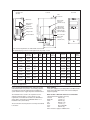
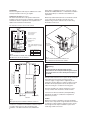
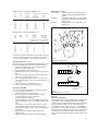
Recommended minimum service clearances:
Left side:
610 mm (24˝)
Right side:
610 mm (24˝)
Front:
1220 mm (48˝)
Top:
610 mm (24˝)
Rear:
610 mm (24˝)
Recommendation
If boiler is located in a confined space, install main gas shut-off
valve (gas cock) and main power supply switch in easily
accessible location outside the confined space.
The boiler model selected should be based on an accurate
heat loss calculation of the building.
General information
Please read and observe the following instructions carefully before
installing the boiler. Install boiler according to these instructions.
Flushing of existing piping
Before boiler is connected to a piping/heating system which has
previously been in service (the ECD is a replacement boiler),
the piping system should be flushed thoroughly with water in
order to remove sludge or other contaminants, especially in
large piping systems such as old gravity pipe systems. Flush
from the top of the system with city water pressure. Failure to
flush out system can lead to deposits in boiler resulting in boiler
failure. This type of failure is not covered under warranty.
Boiler foundation
Provide a solid, level foundation, capable of supporting the weight
of the boiler filled with water, and extending at least 1˝ past the
jacket on all sides. Pour a concrete foundation if necessary. The
boiler must be installed in an indoor heated space.
The boiler should be located near a floor drain.
Do not install boilers on carpeting. Install on non-combustible floor.
Installation, service and maintenance work must be done by
qualified and experienced technicians only. Improper installation,
service or maintenance could create a hazard, resulting in
property damage, severe personal injury, or loss of life.
The ECD Series boiler is for use in closed-loop forced
circulation hot water heating systems only. Boiler operation is
limited by ASME Code to maximum water pressure of 50 psig
and maximum water temperature of 248°F. The vast majority
of applications operate below 30 psig and below 194°F.
Standard equipment on the ECD boiler includes a 30 psig
relief valve and adjustable aquastat with maximum setting of
194°F. An alternate construction is available for operation
between 194°F and 248°F. Consult a Viessmann
representative for alternate construction before ordering boiler.
Necessary permits from local authorities must be obtained
before installing boiler. Installation must be made in
accordance with local ordinances which may differ from the
instructions in this manual.
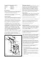
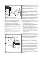
City
water
Supply
Globe Valve
valve
Return
Bypass
Backflow
preventer
Fill valve
Air vent
Strainer
location
Air purger
Circulator
Gas pipe
Approved gas
shut-off valve
Ball
valve
Diaphragm
expansion
tank
30 psig
pressure
relief
valve
Low
water
cut-off
location
ECD boiler
Vent
connection
If the boiler is to be installed on combustible floors or on a
mezzanine, it should be equipped with a special base pan.
Please reference the Viessmann Price List.
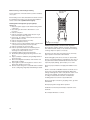
Typical boiler piping is shown in Fig. A.
Vent damper installation
Boilers are sold with a vent damper, packaged separately. The
vent damper must be installed on the boiler to meet minimum
federal efficiency standards. If possible, install vent damper at
the top of the draft hood. Otherwise install vent damper as
close to the boiler as possible.
The vent damper must be field installed on the boiler. Read the
vent damper manufacturer’s instructions before installing the
vent damper. Vent damper must be installed as close as
possible to the boiler flue outlet.
The closing and opening action of the vent damper is driven by
a motor. Spring action is not used to move the vent damper
blade. Do not force vent damper blade by hand. Forcing the
vent damper blade by hand will damage the motor. To observe
the vent damper blade move, turn thermostat up and down
after the vent damper has been installed. Vent damper blade
must be in open position when burner is firing.
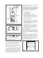
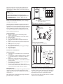
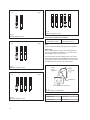
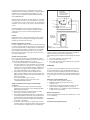
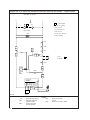
The vent damper must be installed according to Fig. B. The
vent damper may be placed directly on top of the ECD boiler.
Ensure that damper blade rotates freely and is not obstructed
in any way. Read and save the vent damper manufacturer’s
instructions packaged with the vent damper.
After vent damper has been installed on boiler connect the
vent damper cable using the following instructions.
Pressure
gage
1.
2.
3.
Drain
valve
Floor
drain
4.
Level
concrete
floor pad
Fig. A
Typical hot water piping system
Air flow
Remove ECD front panel.
Route the end of the vent damper cable with the Molex
connector through the plastic strain relief on the ECD left
side panel.
Attach Molex connector to vent damper motor using the
metallic strain relief on the vent damper motor to secure
the cable.
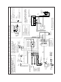
Unplug the two 3-pole #41 plugs inside the boiler and
attach them to the 6-pole plug from the vent damper (see
Figs. B, C and D).