1
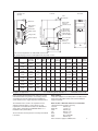
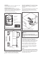
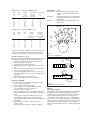
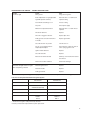
Dim “A”
Molex
connector
ECD-65, -80
47.75˝
ECD-100, -115
48.25˝
ECD-140, -155
48.75˝
ECD-180, -200
52.75˝
There are no serviceable parts on the vent damper. Defective
vent dampers must be replaced.
If the side wall vent system is used, the vent damper must
not be installed. Refer to separate side wall vent system
instructions for series boiler. The side wall vent system
must be purchased separately from the ECD boiler.
Sequence of operation with vent damper:
“A”
Effikal vent
damper only
1.
2.
3.
4.
5.
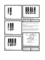
Thermostat calls for heat.
Vent damper blade opens.
Pilot sparks and ignites.
Pilot is proven and main valve is energized.
Main burner and pilot will continue to operate until
thermostat is satisfied. Burner may turn off and on in
response to the adjustable high limit aquastat (SHL1)
setting during a call for heat.
If the vent damper becomes defective:
Plastic
strain
relief
1.
Follow the vent damper manufacturer’s instructions to
leave the vent damper in the “Service” or “Hold Open
Damper” (Effikal) mode by using the service switch on the
damper motor. Vent damper blade should stay open and
boiler should operate normally.
2.
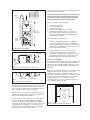
If the procedure in #1 does not work, remove vent
damper, install transitional piece of vent pipe and
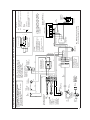
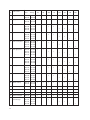
disconnect 6-pole plug from 3-pole plugs. Connect the 3pole plugs together as shown in Fig. D. Refer to wiring
diagrams. Boiler will operate without vent damper.
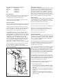
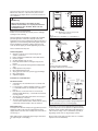
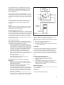
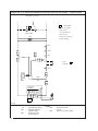
Fig. B
Vent damper harness installation
3-pole
burner plug
41
41
41
3-pole
control plug
6-pole
vent damper
plug
3-pole
burner plug
41
41
Fig. C
Plug connection with vent damper (or power vent)
3-pole
control plug
Fig. D
Plug connection without vent damper
Closet/alcove installation
Models ECD- (65-155) are approved for closet installation with
the clearances shown in Fig.1. Models ECD- (180, 200) are
approved for alcove installation with the clearances shown in
Figs. E and F. Do not use Models ECD- (180, 200) in closet
installations.
Please note that the minimum clearance to combustibles listed
will apply when the boiler is located in a room large in
comparison to the size of the equipment. Please see the
Uniform Mechanical Code for definition. If the boiler is installed
in a space that does not fit the definition of a “room large in
comparison with the size of the equipment”, then it is
considered a closet or an alcove installation and the closet or
alcove installation instructions apply.
The cable must not touch the vent pipe, and any excess cable
must be suitably supported with cable clamps screwed to the
side of the boiler if required. Refer to wiring diagrams. Do not
attach vent damper cable to water or vent pipes.
Damper must be in the open position when main burners are
operating. The damper position indicator (arrow) must be in a
visible location following boiler installation.
The venting system must be arranged so that only the ECD
boiler is served by the vent damper. Maintain a minimum
clearance of 6˝ between the vent damper and combustible
construction. There must be provision for service access to the
vent damper after the installation. Use sheet metal screws
(e.g. #8 x 1⁄2˝) to fasten vent damper to boiler and vent pipe.
Thermostat anticipator should be set at 0.8A.
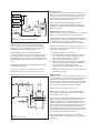
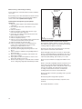
1˝
Top clearance
18˝
6˝
1˝
Top view
Fig. E
Alcove installation for ECD- (180, 200) boiler
5