1
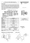
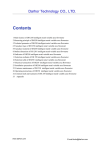
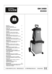
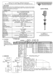
Thank you for choosing a NIVELCO instrument. We are sure that you will be satisfied throughout its use. 1. APPLICATION The NIVOPRESS N submersible hydrostatic level transmitters are applicable for the continuous level measurement of clean or chemically faintly contaminated liquids in bored wells, open reservoirs or tanks. The NC type is recommended for level detection of polluted water. The NIVOPRESS is easy to install in already existing tanks and in deep bored wells and is especially recommneded for controlling of submersible pumps. The use of the supplemental accessories is recommnended. Using the NAW-104 sewage adapter direct contact between the sewage and the diaphragm of the built-in pressure sensor can be avoided. Versions with built-in 4-wire Pt100 temperature sensor are also available. The NK-3- Ex types can be used in explosion hazardous environment. USER’S MANUAL 2. TECHNICAL DATA PROBE Two-wire NPK, NEK, NZK, NCK, NSK NMK TYPE 0 … 200 m water head Ranges Overload allowed (versus range) Outputl Built-in temperature sensor Power supply Max. load (Ut=power supply; Umin = min. transmitter voltage) Current Accuracy Built-in 4-wire temp. sensor Temperature coefficient Operating temperature* Mechanical connection Ingress protection Electrical protection Electrical connection Wire cross section Cable length Probe dimensions Wetted parts Mass Sensor Probe Cable coating Sealing Protecting cap Three-wire NCH 0 … 20 m water head NPH, NZH 0 … 200 m water head See ordercode 20x ( h ≤ 3 m w.h.) 3x 10x ( > 3 m w.h.) 0...+10 V (0 V ≤ 80 mV) a measured to 4 ... 20 mA the „–” power supply NE, NM, NS types: Pt100 „B” class 9 ... 30 V DC 12 ... 30 V DC 18 ... 30 V DC NPK Ex: 12…30 V DC 3x R min U t Umin 0,02 A ≥ 5 kohm – < 6 mA ± 0.5 % ± 0.25 % ± 0.5 % NEK and NSK types only – ≤ ± 0.1 % / 10 K ≤ ± 0.2 % / 10 K -10 ... +60°C 0 ... +60°C -10 ... +60°C NAA-209 cable mounting wedge clamp, NZ and NM types ¾” BSP thread IP 68 Class III. Shielded cable with breathing capillary Ø 7 mm 0.34 mm2 0 ... 300 m (see ordercode) NPH: Ø 22x145 NPK, NEK: Ø 22x145 mm mm Ø40x140mm NZK, NMK: Ø 38x152 NZH: Ø 38x152 mm mm NPK, NEK: probe: 0.2 kg Probe: 0.4 kg probe: 0.2 kg NZK, NMK: probe: 0.3kg Cable: ~ 0,06 kg/m 1.4404 Al2O3 ceramic 1.4404 1.4571 Polyurethane VITON (FKM) ABS – ABS * special order max. +75°C Intrinsical safety NPK-3- 12…30 V DC II 1 G EEx ia IIC T6 Ui = 30 V, Ii = 100 mA, Pi = 0.8 W Ci = 20 nF+ h x 0.04 nF; Li = 100 µH + h x 0.9 µH (h = cable length) ACCESSORIES Cable terminal box Dimensions Ingress protection Operating temperature Material Cable gland Elektromos csatlakozás Cable terminal box with overvoltage protection Data Electrical data Cable mounting wedge clamp Max. mech. Load Operating temperature Overvoltage protection Mounting Dimensions Ingress protection Breakdown voltage Absorbed energy Serial resistance Leakage current * only for 2-wire 4…20mA equipments. 2.1 ACCESSORIES User’s Manual ADDITIONAL DATA FOR EX APPROVED MODELS Tyoe Power supply Ex marking Manufacturer: NIVELCO Process Control Co. H-1043 Budapest, Dugonics u. 11. Phone: (36-1)889-0100 ♦ Fax: (36-1)889-0200 e-mail: [email protected] ♦ www.nivelco.com NAA-101 93 x 93 x 55 mm IP 65 –40 °C … +70 °C Plastic M20x1.5 (cable ∅ 5… ∅ 10 mm) Terminal block for cable with max. cross section of 2.5 mm2 NAA-102 * See: NAA-101 See: OVP NAA-209 With cable length up to 300 m -20 °C … + 60 °C OVP12/33 * OVP32/33 * outdoor DIN 35 mm rail 72 x 42 x 19 mm 62 x 65 x 18 mm IP 54 IP 20 33 V 600 W / 1 ms 13 ohm ≤ 10 µA Certificate of Warranty Declaration of Conformity NAA-101 cable terminal box 2.2 ORDER CODE CODE VERSION CODE RANGE** CODE Normal 2 1 m water h. 1 K H Ex 3 2 m water h. 2 5 m water h. 3 10 m water h. 4 20 m water h. 5 50 m water h. 6 * The order code of an Ex version should end in ‘Ex’ ** Can be set within the range on special request 100 m w.h. 7 200 m w.h. 8 OUTPUT Two-wire 4...20 mA Three-wire 0...10 V Cable terminal box: Optional (to be ordered separately) Cable terminal boksz with OVP: Cable holding assy: Cable mounting wedge clamp: Sewage adapter: OVP units: CABLE LENGTH CODE 0m 0 10 m 1 : : 90 m 9 100 m A 200 m B 300 m C over 100 m TYPE CODE Capacitance C P Piezo Piezo + Pt100 E S Capacitance + Pt100 Piezo, threaded Z Piezo, threaded+Pt100 M up to 100 m * NIVOPRESS N CABLE LENGTH CODE 0m 0 1m 1 : : 9m 9 0m 0 10 m 1 : : 90 m 9 NAA-101 TYPE NAA-102 NAA-105 NAA-209 NAW-104 (for NP types) OVP12/33 (outdoor) OVP32/33 (DIN rail) 2.3 DIMENSIONS NIVOPRESS NP, NE PROBE NIVOPRESS NC, NS PROBE NIVOPRESS NM, NZ PROBE CABLE HOLDING WEDGE CLAMP NAA-209 7 140 Ø7 145 22 Ø 22 40 CABLE TERMINAL BOX NAA-101 és NAA-102 CABLE HOLDING ASSY NAA-105 SEWAGE ADAPTER NAW-104 50 ∅5 breathing capillary 56 93 59 93 1 1/2" BSP Ø21,3 OVERVOLTAGE PROTECTION UNIT OVP 32/33 18 OVERVOLTAGE PROTECTION UNIT 62 70 OVP 12/33 min. 100 mm 3. INSTALLATION For fastening the cable use cable mounting wedge clamp NAA-209 that provides a solution for hanging the cable without slipping and risk of rupture. For the NP, NE types the NAW-104 sewage adapter can be snapped in the place of the plastic protecting cap. STEPS OF INSTALLATION − Feed the special cable through the glands, arrange proper length of cable and fasten the cable with the glands. − Excessive cable parts has to be wound on a pipe with a min. diameter of 100 mm. The special cable must not be cut short! − Let the probe down to the lowest possible point, as only the height of the liquid above the probe will be measured. For connecting the special breathing cable and the signal cable use the cable terminal box NAA101 (accessory) or NAA102 (optional) (with IP65), that accommodates the cable end in an ambience free of dust and humidity. Fasten the cable mounting wedge clamp (e.g. by the use of 2 pcs of M4 screw) to a plain surface. In open air or industrial applications the transmitter should be protected against transient surges / overvoltage. The GND of the OVP must be connected with the shortest possible wire (and without direction changes) to the protecting ground. In this case it is suggested the NAA-102 terminal box (with OVP) is installed close to the location of the measurement. At the opposite end of the cabling the use of an additional overvoltage protection (OVP12/33 or OVP32/33) is advised close to the processing unit. MOUNTING EXAMPLE NAA-101 NAA-102 4. WIRING TWO-WIRE THREE-WIRE TWO-WIRE + Pt100 + – 1 2 3 L 1 4 2 3 L 1 4 2 3 56 7 L 1 2 3 Cable core Color Shielding Positive power supply Yellow Red Black with an additional blue-colored insulation Negative power supply 4 5 6 7 L Voltage output (3-wire type), Pt100 sensor current drive Pt100 sensor current drive Pt100 sensing Pt100 sensing Breathing capillary Uncolored Uncolored Black Black – TWO-WIRE 4 … 20 mA THREE-WIRE 0 … 10 V DC NAA-101 OVP12/33 12 3 L NAA-101 12 NAA-102 wiring of NAA-101 U OUT 3 L 1 5 2 3 L wiring of NAA-102 ALWAYS LEAVE THE BREATHING CAPILLARY FREE! WIRING OF OVP 12/33 WIRING OF OVP 32/33 IN1, IN2 – inputs OUT1, OUT2 – outputs GND – grounding H F O1 G E O2 I1 C A I2 D B I1 (C), I2 (D) – inputs O1 (F), (E) – outputs A, B, H, G – grounding 4.1 SAFETY REGULATIONS FOR THE EX APPROVED UNITS The ’Ex’ type hydrostatic level transmitter must be operated in intrinsically safe circuit only (see values in technical data for Ex approved units). The metal housing of the device must be connected to the EP network using the connection cable marked with 1. INSTALLATION EXAMPLE USING OVP UNITS OPTIONAL PDF-401 PDF-501 12...30V DC OVP12/33 (OVP32/33) OUT NAA-102 IN 4/20 mA IN OVP12/33 OUT 5. PUTTING INTO OPERATION, ADJUSTMENT The unit installed and wired according to the specification is immediately operable, however the specified accuracy will be reached in six-hour time with short cable and in twenty four hour time with a cable of 300 m length. If correction of insertion lenght is needed loosen the cable holding assy then place the probe to the desired level and finally fasten the cable holding assy. 6. MAINTENANCE, REPAIR The unit does not require regular maintenance. In some instances, however, the probe may need occasional cleaning to remove surface deposits within the protective cap that can be easily snapped off. Do not touch the sensor membrane. Repairs during or beyond the guarantee period are to be carried out solely by the Manufacturer. Equipments sent back for repair should be cleaned or sterilised by the User. The User must declare that the above has been carried out. Potecting electrode 7. STORAGE CONDITIONS Ambient temperature: -10 °C … +50 °C Relative humidity: max. 85% 8. WARRANTY All Nivelco products are warranted free of defects in materials or workmanship for a period of two years from the date of purchase, as indicated in the Certificate of Warranty. npk2110a0600h_04 February 2008 Nivelco reserves the right to change technical data without notice!