1
3. INSTALLATION
For fastening the cable use cable mounting wedge clamp NAA-209 that provides a solution for hanging the cable without slipping and risk of rupture.
For the NP, NE types the NAW-104 sewage adapter can be snapped in the place of the plastic protecting cap.
STEPS OF INSTALLATION
−
Feed the special cable through the glands, arrange proper length of cable and fasten the cable with the glands.
−
Excessive cable parts has to be wound on a pipe with a min. diameter of 100 mm.
The special cable must not be cut short!
−
Let the probe down to the lowest possible point, as only the height of the liquid above the probe will be measured.
For connecting the special breathing cable and the signal cable use the cable
terminal box NAA101 (accessory) or NAA102 (optional) (with IP65), that
accommodates the cable end in an ambience free of dust and humidity. Fasten
the cable mounting wedge clamp (e.g. by the use of 2 pcs of M4 screw) to a plain
surface. In open air or industrial applications the transmitter should be protected
against transient surges / overvoltage.
The GND of the OVP must be connected with the shortest possible wire (and
without direction changes) to the protecting ground. In this case it is suggested
the NAA-102 terminal box (with OVP) is installed close to the location of the
measurement. At the opposite end of the cabling the use of an additional overvoltage protection (OVP12/33 or OVP32/33) is advised close to the processing
unit.
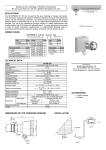
MOUNTING EXAMPLE
NAA-101
NAA-102
4. WIRING
TWO-WIRE
THREE-WIRE
TWO-WIRE +
Pt100
+ –
1
2 3
L
1 4
2 3
L
1 4
2 3
56 7
L
1
2
3
Cable core
Color
Shielding
Positive power supply
Yellow
Red
Black with an
additional blue-colored
insulation
Negative power supply
4
5
6
7
L
Voltage output (3-wire type),
Pt100 sensor current drive
Pt100 sensor current drive
Pt100 sensing
Pt100 sensing
Breathing capillary
Uncolored
Uncolored
Black
Black
–