1
INDOOR UNIT INSTALLATION
MCAC-UTSM-2008-02
match unit opening. All ducts should be suspended using flexible hangers and never fastened directly to the
structure. This unit is not designed for non-ducted (freeblow) applications.
Duct work should be fabricated and installed in accordance with local and/or national codes.
DRAIN CONNECTIONS
All drain lines should be trapped a minimum of three inches, should be pitched away from unit drain pan and
should be no smaller than the coil drain connection.
CAUTION
Drain connection should be hand-tightened, plus no more than 1/16 turn.
Horizontal drain cutout in the center access panel should be removed by using a utility knife. DO NOT TRY
TO KNOCK OUT.
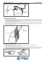
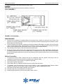
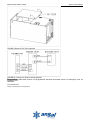
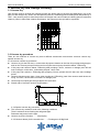
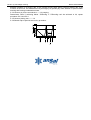
Route the drain line so that it does not interfere with accessibility to the coil, air handling system or filter and
will not be exposed to freezing temperatures. See Figures 1,2 and 3.
NOTE: When the coil is installed in an attic or above a finished ceiling, an auxiliary drain pan should be
provided under the coil as is specified by most local building codes.
Coils should be installed level or pitched slightly toward the drain end. Suggested pitch should not exceed1/4
inch per foot of coil.
The coil is provided with a secondary drain that should be trapped and piped to a location that will give the
occupant a visual warning that the primary drain is clogged. If the secondary drain is not used it must be
capped.
The drain pan connections are designed to ASTM Standard D 2466 Schedule 40. Use 3/4" PVC or steel
threaded pipe. Since the drains are not subject to any pressure it is not necessary to use Schedule 40 pipe
for drain lines.
It is recommended that all drain connections be sealed with teflon tape or equivalent.
ORIFICE INSTALLATION
A standard orifice is preinstalled in the unit and is marked on the unit dataplate. Refer to the outdoor unit
instruction and application data to determine the proper orifice required for your particular system
combination and piping conditions. If the orifice sizes match, nothing further is required and the refrigerant
lines may be connected per the outdoor unit instruction. However, if another orifice should be used, change
the orifice in the coil with the following procedure:
CAUTION
This fitting is a right-hand thread, turn counter-clockwise to remove.
1. Remove the liquid line fitting using 3/4" wrenches, and remove the preinstalled orifice with a small
diameter wire or paper clip.
2. Remove the new orifice from the packet and verify that it is the correct number required. Install this
orifice with the rounded end toward the coil and the flat end outward per Figure 4.
3. Thread the liquid line fitting back in place on the coil. Tighten the fitting hand tight and turn an additional
I/8 turn to seal.