1
Step 4.
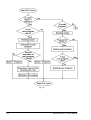
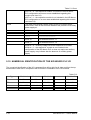
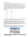
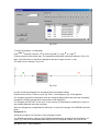
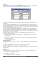
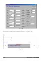
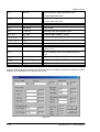
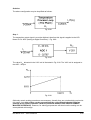
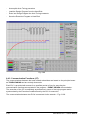
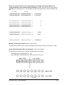
As seen from Fig. 6.94 we refer already to some V-cells which are assigned to the PID
controller. Therefore we have to decide about the PID controller’s Vn cell. With reference to
reliability let us choose V300 as the first PID controller V-cell. According to Table 6.3
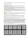
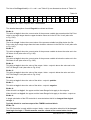
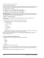
automatically 20 V-cells will be occupied for the PID controller (V300 to V319), each V-cell
assigned to a particular PID controller function / designation as described in Table 6.3.
Step 5.
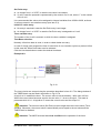
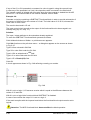
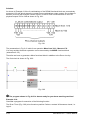
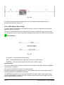
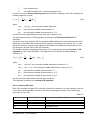
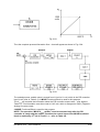
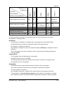
As already explained the calculation of the PID controller is executed by the START (logic 1)
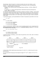
signal (9-th bit of Vn+19 cell – refer to Table 6.4).
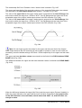
Therefore this 9-th bit must be activated by a time sequence unit, i.e. by a sampling time
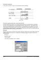
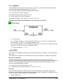
generation unit. Such unit is the TIMER functional block (subsection 6.3.1.) acting as a Pulse
Generator as explained in Fig. 6.21 and Fig. 6.22.
The Set Point operand of the Timer will be entered in Vn+7 (i.e. V307) when programming the
PID controller – refer to Fig. 6.86 and Table 6.3.
The TIMER output will control the 9-th bit of Vn+19 cell assigned to the PID controller.
Step 6.
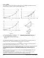
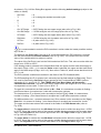
In case the bit No. 11 of Vn+19 (i.e. V319) cell is not activated (i.e. it is at logic 0) the PID
controller will calculate the differential component in an ordinary way as per equation (6.7).
If we want to work in average sliding calculation format (i.e. according equation (6.8)), then
the bit No. 11 of V319 cell must be activated (i.e. at logic 1).
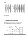
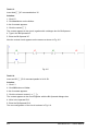
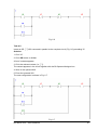
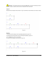
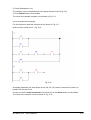
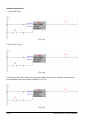
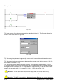
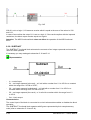
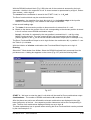
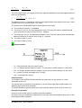
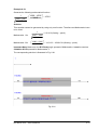
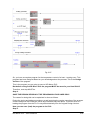
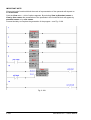
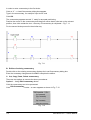
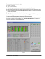
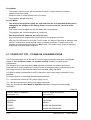
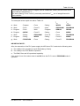
Thus the initial supporting program for the PID controller may be generated as shown
in Fig. 6.95.
6-84
KID Neuro PLC – User’s Manual