1
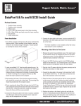
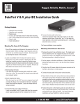
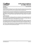
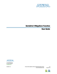
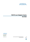
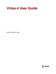
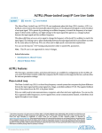
Altera LVDS SERDES IP Core User Guide
2014.08.18
ug_altera_lvds
Subscribe
Send Feedback
The Altera LVDS SERDES IP Core configures the serializer/deserializer (SERDES) and dynamic phase
alignment (DPA) blocks. The IP core also supports LVDS channels placement, legality checks, and LVDS
channel-related rule checks.
®
®
The Altera LVDS SERDES IP core is only available for Arria 10 devices. For Arria V, Cyclone V, and
®
Stratix V devices, follow the steps in Migrating Your ALTLVDS_TX and ALTLVDS_RX IP Cores on
page 25 to migrate your IP.
Related Information
• LVDS SERDES Transmitter/Receiver (ALTLVDS_TX and ALTLVDS_RX) Megafunctions User Guide
Features
You can configure the features of Altera LVDS SERDES IP core through the IP Parameter Editor in the
®
Quartus II software. The Altera LVDS SERDES IP core feature includes the ALTLVDS_RX and
ALTLVDS_TX IP cores features supported in Stratix V devices, such as:
•
•
•
•
•
•
Parameterizable data channel widths
Parameterizable serializer/deserializer (SERDES) factors
Registered input and output ports
PLL control signals
Dynamic phase alignment (DPA) mode
Soft clock data recovery (CDR) mode
Functional Modes
This table lists the functional modes for the Altera LVDS SERDES IP core.
Table 1: Functional Modes for the Altera LVDS SERDES IP Core
Functional Mode
TX
Description
In this mode, the IP core configures the SERDES block as a serializer. A
PLL generates the fast clock (fclk) and load enable (loaden) signals.
© 2014 Altera Corporation. All rights reserved. ALTERA, ARRIA, CYCLONE, ENPIRION, MAX, MEGACORE, NIOS, QUARTUS and STRATIX words
and logos are trademarks of Altera Corporation and registered in the U.S. Patent and Trademark Office and in other countries. All other
words and logos identified as trademarks or service marks are the property of their respective holders as described at
www.altera.com/common/legal.html. Altera warrants performance of its semiconductor products to current specifications in accordance with
Altera's standard warranty, but reserves the right to make changes to any products and services at any time without notice. Altera assumes
no responsibility or liability arising out of the application or use of any information, product, or service described herein except as expressly
agreed to in writing by Altera. Altera customers are advised to obtain the latest version of device specifications before relying on any published
information and before placing orders for products or services.
www.altera.com
101 Innovation Drive, San Jose, CA 95134
ISO
9001:2008
Registered
2
ug_altera_lvds
2014.08.18
Functional Description
Functional Mode
Description
RX Non-DPA Mode
In this mode, you must ensure the correct clock-data alignment, as the
incoming data is captured at the bitslip with the fclk signal. The DPA and
DPA-FIFO are bypassed. As in the transmitter mode, the fclk signal is
provided by a PLL.
RX DPA-FIFO
In this mode, the DPA block selects an optimal phase to sample incoming
data from a set of eight DPA clocks running at the fclk frequency, each 45°
out of phase. The DPA-FIFO, a circular buffer, samples the incoming data
with the selected DPA clock and forwards the data to LVDS clock domain.
The data released from the DPA-FIFO is then sampled at the bitslip circuitry,
where it is lagged, and thus, realigned to match the desired word boundary
when it is deserialized.
To avoid clock metastability issues, after FIFO resets, wait for two core clock
cycles before resetting the bitslip.
Note: All RX channels must be placed in one I/O bank, which supports
up to 24 channels only.
RX Soft-CDR Mode
In this mode, the optimal DPA clock (DPACLK) is forwarded into the LVDS
clock domain, where it is used as the fclk signal. The local clock generator
produces rx_divfwdclk which will be forwarded to the core through a
PCLK network. Note, there is a limitation of the number of soft-CDR
channels due to PCLK usage.
Note: RX interfaces must be placed in one I/O bank, and each bank
only has 12 PCLK resources, hence 12 soft-CDR channels.
Note: For actual soft-CDR supported channel, refer to the respective
device pin out list. Under "Dedicated Tx/Rx Channel", there will
be a value of form LVDS_<BANK_NUMBER>_<PIN_PAIR><p|n>.
The pin pair supports soft-CDR mode only when <PIN_PAIR>
is an even number.
Functional Description
A single Altera LVDS SERDES channel contains a SERDES, a bitslip block, DPA circuitry for all modes, a
high-speed clock tree (LVDS clock tree) and forwarded clock signal for soft-CDR mode. You can configure
the Altera LVDS SERDES channel as a receiver or a transmitter for a single differential I/O. Therefore, an
n-channel LVDS interface contains n-serdes_dpa blocks. The I/O PLLs drive the LVDS clock tree, providing
clocking signals to the Altera LVDS SERDES channel in the I/O bank.
Altera Corporation
Altera LVDS SERDES IP Core User Guide
Send Feedback
ug_altera_lvds
2014.08.18
3
Functional Description
Figure 1: Altera LVDS SERDES Channel Diagram
FPGA
Fabric
Serializer
10
tx_in
tx_out
+
-
DIN DOUT
tx_coreclock
LVDS Transmitter
3
lvds_loaden
lvds_fclk
tx_coreclock
LVDS Receiver
rx_out
+
-
10
Deserializer
Bitslip
DOUT DIN
DOUT DIN
rx_in
DPA Circuitry
DPA FIFO
DOUT DIN
Retimed
Data
DIN
DPA Clock
fclk
Clock
Multiplexer
dpa_fclk
loaden
fclk
3
lvds_fclk
2
dpa_loaden
dpa_fclk
rx_divfwdclk
rx_divfwdclk
rx_coreclock
3
lvds_loaden
lvds_fclk
rx_coreclock
IOPLL
(Local Clock Generator)
8 Serial LVDS
Clock Phases
rx_inclock/tx_inclock
LVDS Clock Domain
DPA Clock Domain
Each Altera LVDS SERDES channel can be broken down into the following paths, with seven functional
units:
Path
TX Data Path
Altera LVDS SERDES IP Core User Guide
Send Feedback
Block
Serializer
Modes
TX mode
Clock Domain
LVDS
Altera Corporation
4
ug_altera_lvds
2014.08.18
Serializer
Path
Block
RX Data Path
Clock Domain
DPA Circuitry
DPA FIFO and Soft- DPA
CDR modes
DPA FIFO
DPA-FIFO mode
Bitslip and
Deserializer
Clock Generation and
Multiplexers
Modes
LVDS-DPA domain crossing
Non-DPA and DPA- LVDS
FIFO modes
Soft CDR modes
DPA clock domain
Local Clock
Generator
Soft-CDR mode
Generates PCLK and
LOADEN in these modes
SERDES Clock
Multiplexers
All modes
Selects LVDS clock sources for
all modes
Serializer
The serializer consists of two sets of registers. The first set of registers captures the parallel data from the
core using the LVDS fast clock. The loaden clock is provided alongside the LVDS fast clock, to enable these
capture registers once per coreclock period. After the data is captured, the data is then loaded into a shift
register, which shifts the LSB towards the MSB, one bit per fast clock cycle. The MSB of the shift register
feeds the LVDS output buffer; hence, higher order bits precede lower order bits in the output bitstream.
The following figure shows the serializer waveform.
Figure 2: LVDS x8 Serializer Waveform
TXDAT[7:0]
76543210
abcdefgh
ABCDEFGH
XXXXXXXX
FCLK
LOADEN
LVDSOUT
X X X X X X X XX X 7 6 5 4 3 2 1 0 a b c d e f g h AB CDE F
This waveform is specific to serialization factor = 8.
Signal
Description
txdat[7:0]
Data to be serialized (supported serialization factors are 3 -10).
fclk
Clock used for transmitter.
loaden
Enable signal for serialization.
lvdsout
LVDS data stream, output from the Altera LVDS SERDES channel.
Altera Corporation
Altera LVDS SERDES IP Core User Guide
Send Feedback
ug_altera_lvds
2014.08.18
DPA FIFO
5
DPA FIFO
In DPA-FIFO mode, the DPA FIFO synchronizes the retimed data to the high-speed LVDS clock domain.
Because the DPA clock may shift phase during the initial lock period, the FIFO must be held in reset state
until the DPA locks; otherwise, there may be a data run-through condition due to the FIFO write pointer
creeping up to the read pointer.
Bitslip
Use bitslip circuitry to insert latencies in increments of one fclk cycle for data word alignment. The data
slips one bit for every pulse of the rx_bitslip_ctrl signal. You must wait at least five core clock cycles
before checking if the data is aligned because it will take at least two core clock cycles to purge the undefined
data.
When enough bitslip signals are sent to rollover the bitslip counter, the rx_bitslip_max status signal is
asserted after five core clock cycles to indicate that it has reached its maximum counter value of the bitslip
counter rollover point.
Deserializer
The deserializer consists of shift registers. The deserialization factor determines the depth of the shift registers.
The loaden signal is a pulse with a frequency of the fclk divided by the deserialization factor. The
deserializer converts a 1-bit serial data stream into a parallel data stream based on the deserialization factor.
Figure 3: LVDS x8 Deserializer Waveform
RX_IN 7 6 5 4 3 2 1 0 a b c d e f g h A B C D E F G H X X X X X X X X
FCLK
LOADEN
RX_OUT[7:0]
XXXXXXXX
76543210
Signal
abcdefgh
ABCDEFGH
Description
rx_in
LVDS data stream, input to the Altera LVDS SERDES channel.
fclk
Clock used for receiver.
loaden
Enable signal for deserialization.
rx_out[7:0]
Deserialized data.
Initialization and Reset
This section describes the initialization and reset aspects, using control characters. This section also provides
a recommended initialization and reset flow for the Altera LVDS SERDES IP core.
Altera LVDS SERDES IP Core User Guide
Send Feedback
Altera Corporation
6
ug_altera_lvds
2014.08.18
Initializing the Altera LVDS SERDES IP Core
Initializing the Altera LVDS SERDES IP Core
With the Altera LVDS SERDES IP core, the PLL must be locked to the reference clock prior to using the
SERDES blocks for data transfer. The PLL starts to lock to the reference clock during device initialization.
The PLL is operational when the PLL achieves lock during user mode. If the clock reference is not stable
during device initialization, the PLL output clock phase shifts becomes corrupted.
When the PLL output clock phase shifts are not set correctly, the data transfer between the high-speed LVDS
domain and the low-speed parallel domain might not be successful, which leads to data corruption. Assert
the pll_areset port for at least 10 ns, and then deassert the pll_areset port and wait until the PLL lock
becomes stable. After the PLL lock port asserts and is stable, the SERDES blocks are ready for operation.
When using DPA, further steps are required for initialization and reset recovery. The DPA circuit samples
the incoming data and finds the optimal phase tap from the PLL to capture data on a receiver channel-bychannel basis. If the PLL has not locked to a stable clock source, the DPA circuit might lock prematurely to
a non-ideal phase tap. Use the rx_dpa_reset port to keep the DPA in reset until the PLL lock signal is
asserted and stable.
The rx_dpa_locked signal asserts when the DPA has found the optimal phase tap.
Note: Altera recommends asserting the rx_fifo_reset port after the rx_dpa_locked signal asserts, and
then deassert the rx_fifo_reset port to begin receiving data.
Each time the DPA shifts the phase taps during normal operation to track variations between the relationship
of the reference clock source and the data, the timing margin for the data transfer between clock domains
is reduced.
The Altera LVDS SERDES IP core asserts the rx_dpa_locked port upon initial DPA lock. When you enable
the Enable DPA loss of lock on one change option, the rx_dpa_locked port deasserts after one change in
phase. If this option is disabled, the rx_dpa_locked signal will deassert after two phase changes in the same
direction.
Note: Altera recommends using the data checkers to ensure data accuracy.
Resetting the DPA
When the data becomes corrupted, you must reset the DPA circuitry using the rx_dpa_reset port and
rx_fifo_reset port.
Assert the rx_dpa_reset port to reset the entire DPA block. This requires the DPA to be trained before it
is ready for data capture.
Note: Altera recommends toggling the rx_fifo_reset port after rx_dpa_locked is asserted. This ensures
the synchronization FIFO is set with the optimal timing to transfer data between the DPA and highspeed LVDS clock domains.
Assert the rx_fifo_reset port to reset only the synchronization FIFO. This allows you to continue system
operation without having to re-train the DPA. Using this port can fix data corruption because it resets the
FIFO; however, it does not reset the DPA circuit.
When the DPA is locked, the Altera LVDS SERDES block is ready to capture data. The DPA finds the optimal
sample location to capture each bit. The next step is to set up the word boundary using custom logic to
control the rx_bitslip_ctrl port on a channel-by-channel basis.
Altera Corporation
Altera LVDS SERDES IP Core User Guide
Send Feedback
ug_altera_lvds
2014.08.18
Aligning the Word Boundaries
7
The bitslip circuit can be reset using the rx_bitslip_reset port. This circuit can be reset anytime and is
not dependent on the PLL or DPA circuit operation.
Aligning the Word Boundaries
To align the word boundaries, it is useful to have control characters in the data stream so that your logic can
have a known pattern to search for. You can compare the data received for each channel, compare to the
control character you are looking for, then pulse the rx_bitslip_ctrl port as required until you successfully
receive the control character.
Note: Altera recommends setting the bitslip rollover count to the deserialization factor or higher, which
allows enough depth in the bitslip circuit to roll through an entire word if required.
If you do not have control characters in the received data, you need a deterministic relationship between
the reference clock and data to predict the word boundary using timing simulation or laboratory measurements. This applies only for non-DPA mode. The only way to ensure a deterministic relationship on the
default word position in the SERDES when the device powers up, or anytime the PLL is reset, is to have a
reference clock equal to the data rate divided by the deserialization factor. For example, if the data rate is
800 Mbps, and the deserialization factor is 8, the PLL requires a 100-MHz reference clock. This is important
because the PLL locks to the rising edge of the reference clock. If you have one rising edge on the reference
clock per serial word received, the deserializer always starts at the same position. Using timing simulation,
or lab measurements, monitor the parallel words received and determine how many pulses are required on
the rx_bitslip_ctrl port to set your word boundaries. You can create a simple state machine to apply the
required number of pulses when you enter user mode, or anytime you reset the PLL.
Note: When using DPA or soft-CDR modes, the word boundary is not deterministic. The initial training
of the DPA allows it to move forward or backward in phase relative to the incoming serial data. Thus,
there can be a ± 1-bit of variance in the serial bit where the DPA initially locks. If there are no training
patterns or control characters available in the serial bit stream to use for word alignment, Altera
recommends using non-DPA mode.
Recommended Initialization and Reset Flow
Altera recommends that you follow these steps to initialize and reset the Altera LVDS SERDES IP core:
1. During entry into user mode, or anytime in user mode operation when the interface requires a reset,
assert the pll_areset and rx_dpa_reset ports.
2. Deassert the pll_areset port and monitor the pll_locked port. For non-DPA mode, skip to step 7.
3. Deassert the rx_dpa_reset port after the pll_locked port becomes asserted and stable.
4. Apply the DPA training pattern and allow the DPA circuit to lock. (If a training pattern is not available,
any data with transitions is required to allow the DPA to lock.) Refer to the respective device data sheet
for DPA lock time specifications.
5. Wait for the rx_dpa_locked port to assert.
6. Assert rx_fifo_reset for at least one parallel clock cycle, and then de-assert rx_fifo_reset.
7. Assert the rx_bitslip_reset port for at least one parallel clock cycle, and then deassert the
rx_bitslip_reset port.
8. Begin word alignment by applying pulses as required to the rx_bitslip_ctrl port.
9. When the word boundaries are established on each channel, the interface is ready for operation.
Altera LVDS SERDES IP Core User Guide
Send Feedback
Altera Corporation
8
ug_altera_lvds
2014.08.18
Signals
Signals
The following tables list the input and output signals for the Altera LVDS SERDES IP core.
Note: N represents the LVDS interface width and the number of serial channels while J represents the
SERDES factor of the interface.
Table 2: Common TX and RX Signals
Signal Name
Width
Direction
Type
Description
inclock
1
Input
Clock
PLL reference clock.
pll_areset
1
Input
Reset
Active-high asynchronous reset to all blocks
in Altera LVDS SERDES and PLL.
pll_locked
1
Output
Control
Width
Direction
Type
rx_in
N
Input
Data
LVDS serial input data.
rx_bitslip_reset
N
Input
Reset
Asynchronous, active-high reset to the clockdata alignment circuitry (bitslip).
rx_bitslip_ctrl
N
Input
Control
Positive-edge triggered increment for bitslip
circuitry. Each assertion adds one bit of
latency to the received bitstream.
rx_dpa_hold
N
Input
Control
Asynchronous, active-high signal prevents
the DPA circuitry from switching to a new
clock phase on the target channel. When held
high, the selected channel(s) hold their
current phase setting. When held low, the
DPA block on selected channel(s) monitors
the phase of the incoming data stream
continuously and selects a new clock phase
when needed. Applicable in DPA-FIFO and
soft-CDR modes only.
rx_dpa_reset
N
Input
Reset
Asynchronous, active-high reset to DPA
blocks. Minimum pulse width is one parallel
clock period. Applicable in DPA-FIFO and
soft-CDR modes only.
rx_fifo_reset
N
Input
Reset
Asynchronous, active-high reset to FIFO
block. Minimum pulse width is one parallel
clock period. Applicable in DPA-FIFO mode
only.
Asserted when internal PLL is locked.
Table 3: RX Signals
Signal Name
Altera Corporation
Description
Altera LVDS SERDES IP Core User Guide
Send Feedback
ug_altera_lvds
2014.08.18
Signals
Signal Name
9
Width
Direction
Type
N*J
Output
Data
Receiver parallel data output. Synchronous
to rx_coreclock in (DPA-FIFO and nonDPA modes). In soft-CDR mode, each
channel has parallel data synchronous to its
rx_divfwdclk.
rx_bitslip_max
N
Output
Control
Bitslip rollover signal. High when the next
assertion of rx_bitslip_ctrl resets the serial
bit latency to 0.
rx_coreclock
1
Output
Clock
Core clock for RX interfaces provided by the
PLL. Not available when using an external
PLL.
rx_divfwdclk
N
Output
Clock
The per channel, divided clock with the ideal
DPA phase. The recovered slow clock for a
given channel. Applicable in soft-CDR mode
only. Because each channel may have a
different ideal sampling phase, the rx_
divfwdclks may not be edge-aligned with
each other. Each rx_divfwdclk must drive
the core logic with data from the same
channel.
rx_dpa_locked
N
Output
Control
Asserted when the DPA block selects the ideal
phase. The Altera LVDS SERDES IP core
drives the rx_dpa_locked port. The DPA
logic asserts the rx_dpa_locked signal when
the signal settles on an ideal phase for that
given channel. The rx_dpa_locked port will
de-assert if the DPA moves two phases in the
same direction or if the DPA moves one
phase. The rx_dpa_locked signal will still
toggle when the rx_dpa_hold signal is
asserted, and should be ignored by user logic
when the rx_dpa_hold signal is asserted.
Applicable in DPA-FIFO and soft-CDR
modes only.
Width
Direction
Type
N*J
Input
Data
Parallel data from the core.
tx_out
N
Output
Data
LVDS serial output data.
tx_outclock
1
Output
Clock
External reference clock (sent off chip via the
TX data path). Source-synchronous with tx_
out.
rx_out
Description
Table 4: TX Signals
Signal Name
tx_in
Altera LVDS SERDES IP Core User Guide
Send Feedback
Description
Altera Corporation
10
ug_altera_lvds
2014.08.18
Signals
Signal Name
tx_coreclock
Width
Direction
Type
1
Output
Clock
Description
The clock that drives the core logic feeding the
serializer. Not available in the external PLL
mode.
Table 5: External PLL Signals
For instructions on setting the frequencies, duty cycles, and phase shifts of the required PLL clocks for external PLL
mode, refer to the Clock Resource Summary tab in the IP Parameter Editor.
Signal Name
Width
Direction
Type
ext_fclk
1
Input
Clock
LVDS fast clock. Used for serial data transfer.
Required in all modes. You must connect this
signal to the lvds_clk[0] port of the PLL.
This signal is configured as outclock[0] from
the PLL. Use Enable access to PLL LVDS_
CLK/LOADEN output port in the IOPLL
generation.
ext_loaden
1
Input
Clock
LVDS load enable. Used for parallel load. Not
required in RX Soft-CDR mode. You must
connect this signal to the loaden[0] port of
the PLL. This signal is configured as
outclock[1] from the PLL. Use Enable access
to PLL LVDS_CLK/LOADEN output port
in the IOPLL generation.
ext_coreclock
1
Input
Clock
The clock that drives the core logic feeding the
serializer (TX) / receiving from the deserializer
(RX). This signal is still present in RX softCDR mode, even though the RX core registers
are clocked using the rx_divfwdclk.
Input
Clock
Required for RX DPA-FIFO and RX Soft-CDR
modes only. Provides the VCO clocks to the
DPA circuitry for optimal phase selection. You
must connect this signal to the phout[7:0]
signal from the PLL. Use Enable access to PLL
DPA output port in IOPLL generation.
ext_vcoph[7:0]
Description
ext_pll_locked
1
Input
Data
PLL lock signal. Required for RX DPA-FIFO
and RX Soft-CDR modes only.
ext_tx_outclock_fclk
1
Input
Clock
Phase-shifted version of fast clock required
for TX outclock phase shifts that are not
multiples of 180 degrees.
ext_tx_outclock_loaden
1
Input
Clock
Phase-shifted version of loaden required for
TX outclock phase shifts that are not multiples
of 180 degrees.
Altera Corporation
Altera LVDS SERDES IP Core User Guide
Send Feedback
ug_altera_lvds
2014.08.18
Parameter Settings
11
Parameter Settings
You can parameterize the Altera LVDS SERDES IP core using the IP Parameter Editor.
General Settings Tab
Parameter
Value
Functional mode
•
•
•
•
Number of channels
• 1 to 72 for TX
Specifies the number of serial channels in the
• 1 to 24 for RX Non- interface.
DPA
• Decrement one channel for the dedicated
• 1 to 24 for RX DPAreference clock pin (refclk) for TX, RX
FIFO
Non-DPA, and RX DPA. Not using the
• 1 to 12 for RX Softdedicated reference clock pin may
CDR
contribute to higher jitter.
• Decrease by one channel for the TX
outclock pin (tx_outclock) if used.
Data rate
SERDES factor
TX
RX Non-DPA
RX DPA-FIFO
RX Soft-CDR
Description
150.0 to 1600.0
When enabled, the IP core bypasses the PLL
and the interface is driven with a clock pin.
—
Altera LVDS SERDES IP Core User Guide
Send Feedback
Specifies the data rate (in Mbps) of a single
serial channel. The value is dependent on the
Functional mode parameter settings.
3, 4, 5, 6, 7, 8, 9, and 10 Specifies the serialization rate or deserialization rate for the LVDS interface.
Use clock-pin drive
Use backwards-compatible port
names
Specifies the functional mode of the interface.
—
Note: This feature is not supported in
the current version of the Quartus
II software.
When enabled, the IP core uses legacy toplevel names that are compatible with
ALTLVDS_TX and ALTLVDS_RX IP cores.
Altera Corporation
12
ug_altera_lvds
2014.08.18
PLL Settings Tab
PLL Settings Tab
Parameter
Value
Use external PLL
—
Description
When enabled, the IP core does not instantiate a
PLL locally. Instead, a series of clock connections
are elaborated with the prefix "ext" that should be
connected to an externally generated PLL. This
option allows you to access all of the available
clocks from the PLL, as well as use advanced PLL
features such as clock switchover, bandwidth
presets, dynamic phase stepping, and dynamic
reconfiguration.
The Clock Resource Summary tab guides you to
configure your external PLL.
Desired inclock frequency
Actual inclock frequency
FPGA/PLL speed grade
—
Specifies the inclock frequency in MHz
—
Specifies the closest inclock frequency to the
desired frequency that can source the interface.
—
Specifies the FPGA/PLL speed grade which
determines the operation range of the PLL.
Enable pll_areset port
—
When enabled, this parameter exposes the pll_
areset port, which you can use to reset the entire
LVDS interface.
Core clock resource type
—
Specifies which clock network the Altera LVDS
SERDES IP core should export an internally
generated coreclock onto.
Note: This feature is not supported in the
current version of the Quartus II
software. However, this can be
manually added using QSF
assignments.
Receiver Settings Tab
Parameter
Value
Description
Bitslip Settings
Enable bitslip mode
Altera Corporation
—
When enabled, this parameter adds a bitslip block
to the data path of the receiver and exposes the rx_
bitslip_ctrl port (one input per channel). Every
assertion of the rx_bitslip_ctrl signal adds one
bit of serial latency to the data path of the specified
channel.
Altera LVDS SERDES IP Core User Guide
Send Feedback
ug_altera_lvds
2014.08.18
Receiver Settings Tab
Parameter
Value
13
Description
Enable rx_bitslip_reset port
—
When enabled, this parameter exposes the rx_
bitslip_reset port (one input per channel), which
you can use to reset the bitslip.
Enable rx_bitslip_max port
—
When enabled, this parameter exposes the rx_
bitslip_max port (one output per channel). When
asserted, the next rising edge of rx_bitslip_ctrl
resets the latency of the bitslip to zero.
Bitslip rollover value
3, 4, 5, 6, 7, 8, 9, Sets the maximum latency that can be injected using
10, 11
bitslip. When it reaches that value, it rolls over and
the rx_bitslip_max signal is asserted. The default
value is 10.
Note: Altera recommends setting this
parameter to a value equal to or greater
than the deserialization factor.
DPA Settings
Enable rx_dpa_reset port
—
When enabled, the IP core exposes the rx_dpa_
reset port, which you can use to reset the DPA
logic of each channel independently. Formerly
known as rx_reset.
Enable rx_fifo_reset port
—
When enabled, user logic drives the rx_fifo_reset
port which you can use to reset the DPA-FIFO
block.
Enable rx_dpa_hold port
—
When enabled, the IP core exposes the rx_dpa_
hold input port (one input per channel). When set
high, the DPA logic in the corresponding channel
does not switch sampling phases. The rx_dpa_hold
port is formerly known as rx_dpll_hold port.
Altera LVDS SERDES IP Core User Guide
Send Feedback
Altera Corporation
14
ug_altera_lvds
2014.08.18
Receiver Settings Tab
Parameter
Value
Enable DPA loss of lock on one
change
—
Description
When enabled, the Altera LVDS SERDES IP core
drives the rx_dpa_locked signal low when the DPA
changes phase selection from the initially locked
position. The Altera LVDS SERDES IP core drives
the rx_dpa_locked signal high if the DPA changes
the phase selection back to the initial locked
position.
When disabled, the Altera LVDS SERDES IP core
drives the rx_dpa_locked signal low when the DPA
moves two phases in the same direction away from
the initial locked position. The Altera LVDS
SERDES IP core drives the rx_dpa_locked signal
high if the DPA changes the phase selection to be
within one phase or same phase as the initial locked
position.
A de-assertion of rx_dpa_locked does not indicate
the data is invalid, it indicates the DPA has changed
phase taps to track variations between the inclock
and rx_in data. Altera recommends using data
checkers to verify data accuracy.
Enable DPA alignment only to
rising edges of data
—
When enabled, DPA logic counts the rising edges
on the incoming serial data only. When disabled,
DPA logic counts the rising and falling edges.
Note: This port is only recommended for use
in high jitter systems, and Altera
recommends disabling this port in
typical applications.
(Simulation only) Specify PPM drift
on the recovered clock(s)
—
Specifies the amount of phase drift the ALTERA_
LVDS simulation model should add to the
recovered rx_divfwdclks.
Note: This feature is not supported in the
current version of the Quartus II
software.
Non-DPA Settings
Desired receiver inclock phase shift
(degrees):
Altera Corporation
—
Specifies the ideal phase delay of the inclock with
respect to transitions in the incoming serial data in
degrees of the LVDS fast clock. For example,
specifying 180 degrees implies the inclock is center
aligned with the incoming data.
Altera LVDS SERDES IP Core User Guide
Send Feedback
ug_altera_lvds
2014.08.18
Transmitter Settings Tab
Parameter
Value
15
Description
Actual receiver inclock phase shift Legal values are Specifies the closest achievable receiver inclock
(degrees)
dependent on the phase shift to the desired receiver inclock phase
fclk and inclock shift.
frequencies.
Refer to Setting
the Receiver
Input Clock
Parameters on
page 16.
Transmitter Settings Tab
Parameter
TX core registers clock
Value
Allows you to either clock the core registers with
the tx_coreclock or the PLL refclk. If you select
tx_coreclock or inclock, the refclk frequency must be equal to the
data rate divided by the serialization factor.
inclock
This parameter is available in TX functional mode
only.
Enable tx_coreclock port
—
When enabled, the IP core exposes the tx_
coreclock port which you can use to drive the core
logic feeding the transmitter.
—
When enabled, the IP core exposes the tx_
outclock port. The frequency of the tx_outclock
port is dependent on the setting for the tx_outclock
division factor parameter. The phase of the tx_
outclock port is dependent on the Desired tx_
outclock phase shift parameter. This parameter
takes up an additional channel, which reduces the
max number of channels per TX interface by 1
Enable tx_outclock port
Desired tx_outclock phase shift
(degrees)
Altera LVDS SERDES IP Core User Guide
Send Feedback
Description
Refer to the
Setting the
Transmitter
Output Clock
Parameters on
page 17.
Allows you to specify the phase relationship
between the outclock and outgoing serial data in
degrees of the LVDS fast clock.
Altera Corporation
16
ug_altera_lvds
2014.08.18
Clock Resource Summary Tab
Parameter
Value
Description
Actual tx_outclock phase shift
(degrees)
Legal values are Specifies the closest achievable tx_outclock phase
dependent on the shift to the desired tx_outclock phase shift.
fclk and tx_
outclock
frequencies. Refer
to Setting the
Transmitter
Output Clock
Parameters on
page 17.
Tx_outclock division factor
Legal values are
dependent on the
serialization
factor.
Allows you to specify the ratio of the fast clock
frequency to the outclock frequency (for example,
the maximum number of serial transitions per
outclock cycle).
Clock Resource Summary Tab
This tab in the parameter editor lists out all the required frequencies, phase shifts, and duty cycles of the
required clocks, including instructions on the required connections. This tab also shows how to configure
and connect an external PLL.
Setting the Receiver Input Clock Parameters
When using non-DPA mode, if you want the SERDES receiver to sample the source synchronous data, you
must specify the inclock relationship to the rx_in data. To do so, type a value in the Desired receiver inclock
phase shift (degrees) parameter. Legal values are evenly divisible by 45. If you enter an illegal value, the
actual phase shift will appear in Actual receiver inclock phase shift (degrees).
For rising inclock edge aligned interfaces to the rx_in data (Figure 4), select 0° as the desired receiver clock
phase shift. The PLL will be set with the required phase shift on fclk to center it at the SERDES receiver.
Figure 4: 0° Edge Aligned inclock x8 Deserializer Waveform With Single Rate Clock
The phase shift you specify will be relative to the fclk which operates at the serial data rate. Phase shift
values between 0° and 360° are used to specify the rising edge of the inclock within a single bit period. The
maximum phase shift value is determined by the following equation:
(Number of fclk periods per inclock period x 360) - 1
Altera Corporation
Altera LVDS SERDES IP Core User Guide
Send Feedback
ug_altera_lvds
2014.08.18
Setting the Transmitter Output Clock Parameters
17
Specifying phase shift values greater than 360° will change the MSB location within the parallel data.
Note: By default, the MSB from the serial data will not be the MSB on the parallel data. You can use bitslip
to set the proper word boundary on the parallel data. Refer to Aligning the Word Boundaries for
more details.
To specify a center aligned inclock to rx_in relationship (Figure 5), enter a phase shift value of 180° for the
Desired receiver inclock phase shift (degrees) parameter.
Figure 5: 180° Center Aligned inclock x8 Deserializer Waveform With Single Rate Clock
The phase shift value you enter to specify the inclock to rx_in relationship is independent of the inclock
frequency. To specify a center aligned DDR inclock to rx_in relationship (Figure 6), enter a phase shift
value of 180° for the Desired receiver inclock phase shift (degrees) parameter.
Figure 6: 180° Center Aligned inclock x8 Deserializer Waveform With DDR Clock
Setting the Transmitter Output Clock Parameters
The tx_outclock relationship to the tx_out data is specified with two parameters:
• Desired tx_outclock phase shift (degrees)
• Tx_outclock division factor
These parameters set the phase and frequency of the tx_outclock based on the fclk which operates at the
serial data rate. You can specify the desired tx_outclock phase shift relative to the tx_out data at 45°
increments of the fclk. You can set the tx_outclock frequency using the available division factors from
the drop-down list.
Use 0° to specify the tx_outclock phase to be rising edge aligned to the MSB of the serial data on tx_out
(Figure 7).
Altera LVDS SERDES IP Core User Guide
Send Feedback
Altera Corporation
18
ug_altera_lvds
2014.08.18
Setting the Transmitter Output Clock Parameters
Figure 7: 0° Edge Aligned tx_outclock x8 Serializer Waveform with Division Factor of 8
Use 180° to specify the tx_outclock phase to center aligned to the MSB of the serial data on tx_out (Figure
8).
Figure 8: 180° Center Aligned tx_outclock x8 Serializer Waveform with Division Factor of 8
Phase shift values of 0° through 315° will position the rising edge of the tx_outclock within the MSB of the
tx_out data. Phase shift values beginning with 360° will position the rising edge of the tx_outclock in serial
bits after the MSB. For example, a phase shift of 540° will position the rising edge in the center of the bit
after the MSB (Figure 9).
Figure 9: 540° Center Aligned tx_outclock x8 Serializer Waveform with Division Factor of 8
Use the Tx_outclock division factor drop-down list to set the tx_outclock frequency. Figure 10 shows a
x8 serialization factor using a 180° phase shift with a tx_outclock division factor of 2 (DDR clock and data
relationship).
Altera Corporation
Altera LVDS SERDES IP Core User Guide
Send Feedback
ug_altera_lvds
2014.08.18
Timing
19
Figure 10: 180° Center Aligned tx_outclock x8 Serializer Waveform with Division Factor of 2
Timing
To properly perform timing analysis on the Altera LVDS SERDES IP core on Arria 10 devices, the Quartus
II software version 14.0a10 generates the required timing constraints.
Timing Components
Table 6: Timing Components
This table lists the timing components for the Altera LVDS SERDES IP core.
Timing Component
Source Synchronous Paths
Description
The source synchronous paths are paths where clock and data signals
are passed from the transmitting devices to the receiving devices. For
example:
• FPGA/LVDS/TX to external receiving device transmitting path
• External transmitting device to FPGA/non-DPA mode/LVDS/RX
receiving path
Dynamic Phase Alignment Paths
The I/O capture paths in soft-CDR and DPA-FIFO modes are registered
by a DPA block, which dynamically chooses the best phase from the
PLL VCO clocks to latch the input data.
Internal FPGA Paths
The internal FPGA paths are the paths inside the FPGA fabric. This
includes the LVDS RX hardware to core registers paths, core registers
to LVDS TX hardware paths and others core registers to core registers
path. The TimeQuest Timing Analyzer reports the corresponding
timing margins.
Timing Constraints and Files
To enable you to perform timing analysis on the Altera LVDS SERDES IP core successfully, the IP core
generates the following timing files, which you can locate in the <variation_name> directory.
Altera LVDS SERDES IP Core User Guide
Send Feedback
Altera Corporation
20
ug_altera_lvds
2014.08.18
Timing Analysis
Table 7: Timing Files
File
Description
<variation_name>_altera_lvds_core20_140_<random_id> This .sdc allows the Fitter to optimize timing
.sdc
margins with timing driven compilation. Also
allows the TimeQuest timing analyzer to
analyze the timing of your design.
The IP core uses the .sdc for the following
operations:
•
•
•
•
Creating clocks on PLL inputs
Creating generated clocks
Calling derive_clock_uncertainty
Creating proper multi-cycle constraints
You can locate this file in the .qip generated
during the IP generation.
sdc_util.tcl
This .tcl file is a library of functions and
procedures that the .sdc uses.
Timing Analysis
Timing Analysis at I/O
This section describes the timing analysis at the I/O interfacing external devices.
Soft CDR Mode and DPA-FIFO Mode RX
In soft CDR and DPA-FIFO mode, the receiving data is captured dynamically by the DPA hardware. As a
result, the TimeQuest Timing Analyzer does not perform static timing analysis at the I/O.
Non-DPA Mode RX and Receiver Skew Margin (RSKM)
Changes in the system environment, such as temperature, media (cable, connector, or PCB), and loading,
affect the receiver's setup and hold times; internal skew affects the sampling ability of the receiver.
In non-DPA mode, use receiver skew margin (RSKM), receiver channel-to-channel skew (RCCS), and
sampling window (SW) specifications to analyze the timing for high-speed source-synchronous differential
signals in the receiver data path. The following equation shows the relationship between RSKM, RCCS, and
SW.
Figure 11: RSKM
Altera Corporation
Altera LVDS SERDES IP Core User Guide
Send Feedback
ug_altera_lvds
2014.08.18
Non-DPA Mode RX and Receiver Skew Margin (RSKM)
21
Where:
• RSKM—is the timing margin between the receiver's clock input and the data input SW.
• Time unit interval (TUI)—is the time period of the serial data (1/fMAX). Also known as the LVDS period
in the TimeQuest Timing Analyzer section in the Quartus II Compilation Report.
• SW—is the period of time that the input data must be stable to ensure that data is successfully sampled
by the LVDS receiver. The SW is a device property and varies with device speed grade.
• RCCS— is the timing difference between the fastest and slowest input transitions, including tCO variations
and clock skew. Specify RCCS by applying minimum and maximum set_input_delay constraints to
the receiver inputs, where RCCS is the difference between the maximum and minimum value.
The following figure shows the relationship between the RSKM, RCCS, and SW.
Figure 12: Differential High-Speed Timing Diagram and Timing Budget for Non-DPA Mode
Timing Diagram
External
Input Clock
Time Unit Interval (TUI)
Internal
Clock
RCCS
Receiver
Input Data
RCCS
RSKM
SW
t SW (min)
Bit n
Timing Budget
Internal
Clock
Falling Edge
RSKM
t SW (max)
Bit n
TUI
External
Clock
Clock Placement
Internal
Clock
Synchronization
Transmitter
Output Data
RSKM
RSKM
RCCS
RCCS
2
Receiver
Input Data
SW
You must calculate the RSKM value to decide whether you can properly sample the data by the LVDS receiver
with the given data rate and device. A positive RSKM value indicates the LVDS receiver can properly sample
the data; a negative RSKM value indicates the receiver cannot properly sample the data.
The following example shows the RSKM calculation.
Altera LVDS SERDES IP Core User Guide
Send Feedback
Altera Corporation
22
ug_altera_lvds
2014.08.18
Obtaining Accurate RSKM Results in the TimeQuest Timing Analyzer
Data Rate: 1 Gbps, Board channel-to-channel skew = 200 ps
RCCS = 100 ps (pending characterization)
SW = 300 ps (pending characterization)
TUI = 1000 ps
Total RCCS = RCCS + Board channel-to-channel skew= 100 ps + 200 ps
= 300 ps
RSKM =
= 1000 ps - 300 ps - 300 ps
= 400 ps > 0
Because the RSKM > 0 ps, receiver non-DPA mode must work correctly.
Obtaining Accurate RSKM Results in the TimeQuest Timing Analyzer
To obtain accurate RSKM results in TimeQuest Timing Analyzer, specify your RCCS (in nanoseconds) in
the SDC file:
##########################################################################################
# Modifiable user variables
# Change these values to match your design.
##########################################################################################
set ::RCCS 0.0
Obtaining RSKM Report
For LVDS receivers, the Quartus II software provides the RSKM report showing SW, TUI or LVDS period,
and RSKM values for non-DPA mode. You can generate the RSKM report by executing the report_rskm
command in the TimeQuest Timing Analyzer.
To obtain the RSKM report, follow these steps:
1. In the Quartus II software, under the Tools menu, click TimeQuest Timing Analyzer
2. In the TimeQuest Timing Analyzer window, under Reports, select Device Specific and click Report
RSKM.
TX and Transmitter Channel-to-Channel Skew (TCCS)
For LVDS TX, the TimeQuest Timing Analyzer reports the TCCS at the I/O analysis. TCCS is the maximum
skew observed across the channels of data and TX output clock.
Altera Corporation
Altera LVDS SERDES IP Core User Guide
Send Feedback
ug_altera_lvds
2014.08.18
Obtaining TCCS Report
23
Obtaining TCCS Report
For LVDS transmitters, the TimeQuest Timing Analyzer provides a TCCS report, which shows TCCS values
for serial output ports.
To obtain the TCCS report (report_tccs), follow these steps:
1. In the Quartus II software, under the Tools menu, click TimeQuest Timing Analyzer.
2. From the TimeQuest Timing Analyzer, under Reports, select Device Specific and click Report TCCS
Timing Analysis in FPGA
The Altera LVDS SERDES IP core generation creates the clock settings of the SERDES hardware and the
core clock for a successful timing analysis of the IP core.
Table 8: Clock for the TX, Non-DPA RX, and DPA-FIFO RX Mode
This table lists the clock for TX, non-DPA RX, and DPA-FIFO RX modes. Because the frequency of LVDS fast clock
is higher than the user core clock by the serialization factor, the IP generation also creates multicycle path constraints
for proper timing analysis at the SERDES - core interface.
Clock
Description
Core clock
<pll_instance_name>_*_outclk[*]
LVDS fast clock
<pll_instance_name>_*_lvds_clk[*]
Table 9: Clock for Soft-CDR RX Mode
This table lists the clock for soft-CDR RX mode.
Clock
Description
Core clock
<lvds_instance_name>_core_ck_name_<channel_num>
DPA fast clock
<lvds_instance_name>_dpa_ck_name_<channel_num>
To ensure proper timing analysis, instead of multicycle constraints, the IP core generation creates clock
settings at rx_out in the format of <lvds_instance_name>_core_data_out_<channel_num>_<bit> for
rising edge data and <lvds_instance_name>_core_data_out_<channel_num>_<bit>_neg for falling edge
data.
With these proper clock settings, the TimeQuest Timing Analyzer will timing analyze the LVDS SERDES Core interface transfer and the within core transfer correctly.
External PLL Mode
When you enable the Use external PLL parameter in the PLL Settings tab, the IP generation does not create
clock settings for the PLL input and output. You must ensure the PLL clock settings are correct.
However, because some of the SERDES constraints derived from the PLL clocks, those PLL clock settings
must already be created when the .sdc of the Altera LVDS SERDES is being read. To ensure that the .sdc
has the PLL clock settings was read before the one for LVDS SERDES, ensure that the .sdc of the PLL appears
before the LVDS SERDES .qip in the .qsf of your project.
Altera LVDS SERDES IP Core User Guide
Send Feedback
Altera Corporation
24
ug_altera_lvds
2014.08.18
Timing Closure
Timing Closure
Timing Violation in Internal FPGA Paths
An LVDS SERDES design with high frequency and low SERDES factor is prone to have challenges at closing
timing at internal FPGA paths.
If setup violation is observed, consider the following guidelines:
• If setup violation from core registers to LVDS TX hardware is reported, check the TX core registers
clock parameter. If it is set to inclock, consider changing to tx_coreclock. Core registers using tx_coreclock
have less clock delay because of the PLL compensation delay on the tx_coreclock path. This can result
in less source clock delay which gives more setup slack to such transfer.
• However, if the TX core registers clock parameter is set to tx_coreclock, consider lowering the data rate
or increasing the SERDES factor to reduce the core frequency requirement and to provide more setup
slack.
If hold violation from LVDS RX to core registers is observed, consider the following guideline:
• Check the setup slack for such transfer. If there is ample setup slack, you may attempt to over-constraint
the hold for such transfer. Under normal circumstances, the Fitter should try to fix hold violation by
adding delay. It is possible that the Fitter may think adding more delay to avoid hold violation at the fast
corner will hurt setup at the slow corner.
Design Example
The Altera LVDS SERDES IP core can generate a design example that matches the same configuration chosen
for the IP core. The design example is a simple design that does not target any specific application; however
you can use the design example as a reference on how to instantiate the IP core and what behavior to expect
in a simulation.
Generating Design Example
During generation, the Generation dialog box displays the option to generate a design example. Turn on
the Generate Example Design option.
The software generates the <instance>_example_design directory along with the IP core, where <instance>
is the name of your IP core.
The <instance>_example_design directory contains two TCL scripts:
• - make_qii_design.tcl
• - make_sim_design.tcl
Generating Quartus Design Example
The make_qii_design.tcl generates a synthesizable design example along with a Quartus project, ready
for compilation.
To generate synthesizable design example, run the following script at the end of IP generation:
quartus_sh -t make_qii_design.tcl
Altera Corporation
Altera LVDS SERDES IP Core User Guide
Send Feedback
ug_altera_lvds
2014.08.18
Generating Simulation Design Example
25
To specify an exact device to use, run the following script:
quartus_sh -t make_qii_design.tcl [device_name]
This script generates a qii directory containing a project called ed_synth.qpf. You can open and compile
this project with the Quartus II software.
Generating Simulation Design Example
The make_sim_design.tcl generates a simulation design example along with tool-specific scripts to compile
and elaborate the necessary files.
To generate a simulation design example, run the following script at the end of the IP core generation:
quartus_sh -t make_sim_design.tcl
To generate simulation design example for a VHDL-only simulator, run the following script:
quartus_sh -t make_sim_design.tcl VHDL
This script generates a sim directory containing one subdirectory for each supported simulation tools. Each
subdirectory contains the specific scripts to run simulation with the corresponding tool.
The simulation design example is made of a driver connected to the generated IP core. The driver generates
random traffic and internally checks the legality of the outgoing data.
References
IP Migration Flow for Arria V, Cyclone V, and Stratix V Devices
The IP migration flow allows you to migrate the ALTLVDS_TX and ALTLVDS_RX IP cores of Arria V,
Cyclone V, and Stratix V devices to the Altera LVDS SERDES IP core of Arria 10 devices.
This IP migration flow configures the Altera LVDS SERDES IP core to match the settings of the ALTLVDS_TX
and ALTLVDS_RX IP cores, allowing you to regenerate the IP core.
Note: Some IP cores only support the IP migration flow in specific modes. If your IP core is in a mode that
is not supported, you may need to run the IP Parameter Editor for the Altera LVDS SERDES IP core
and configure the IP core manually.
Migrating Your ALTLVDS_TX and ALTLVDS_RX IP Cores
To migrate your ALTLVDS_TX and ALTLVDS_RX IP cores, follow these steps:
1. Open your ALTLVDS_TX or ALTLVDS_RX IP core in the IP Parameter Editor.
2. In the Currently selected device family, select Arria 10.
3. Click Finish to open the Altera LVDS SERDES IP Parameter Editor. The IP Parameter Editor configures
the Altera LVDS SERDES settings similarly to the ALTLVDS_TX or ALTLVDS_RX IP core settings.
4. If there are any incompatible settings between the two, select new supported settings.
5. Click Finish to regenerate the IP core.
Altera LVDS SERDES IP Core User Guide
Send Feedback
Altera Corporation
26
ug_altera_lvds
2014.08.18
Comparison with Stratix V Devices
6. Replace your ALTLVDS_TX or ALTLVDS_RX IP core instantiation in RTL with the Altera LVDS SERDES
IP core.
Note: The Altera LVDS SERDES IP core port names may not match the ALTLVDS_TX or ALTLVDS_RX
IP core port names, so simply changing the IP core name in the instantiation may not be sufficient.
Comparison with Stratix V Devices
The Altera LVDS SERDES IP core has similar features to the Stratix V SERDES feature. The key difference
is the clock network and the ubiquitous RX and TX resource in LVDS I/O banks.
Table 10: Arria 10 and Stratix V Devices Feature Comparison
Features
Arria 10 Devices
Stratix V Devices
Operation Frequency Range
150 MHz - 1.6 GHz
Serialization/Deserialization
Factors
3 to 10
Regular DPA and non-DPA
mode
Supported
Clock Forwarding for SoftCDR
Supported
RX Resource
Every I/O pair
(Every two I/O pairs for CDR)
TX Resource
PLL Resource
Every I/O pair
Every two I/O pairs on every side without HSSI
transceivers
Every two I/O pairs every side without HSSI
transceivers
TX channels can span three RX and TX channels placed on one edge can be
adjacent banks, driven by the
driven by the corner or center PLL.
IOPLL in the middle bank.
RX channels are driven by the
IOPLL in the same bank.
Number of DPA Clock Phase
I/O Standard
Altera Corporation
8
True LVDS
True LVDS, pseudo-differential output
Altera LVDS SERDES IP Core User Guide
Send Feedback
ug_altera_lvds
2014.08.18
Document Revision History
27
Document Revision History
Table 11: Document Revision History
Date
Version
August, 2014
2014.08.18
• Clarified that you must wait five core clock cycles before checking
if the data is aligned for bitslip circuitry.
• Changed the rx_out[9:0] signal to rx_out[7:0] for the
deserializer.
• Clarified that if one of the pins is taken for the refclk, then the
value is 1 to 71 for TX and 1 to 23 for RX. This change is
implemented for the Number of channels parameter.
• Clarified that if one of the pins is taken for the tx_outclock,
then the value is 1 to 71 for TX. This change is implemented for
the Number of channels parameter.
• Added a new parameter (Use backwards-compatible port
names).
• The Use external PLL is supported in the 14.0a10 release. The
Clock Resource Summary tab guides you to configure your
external PLL.
• Removed the Enable pll_locked port and Enable rx_dpa_locked
port parameters.
• Added the external PLL signals.
• Added timing information.
November, 2013
2013.11.29
Initial release.
Altera LVDS SERDES IP Core User Guide
Send Feedback
Changes
Altera Corporation