1
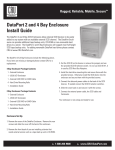
Rugged, Reliable, Mobile, Secure
TM
DataPort V & V plus IDE Installation Guide
Package Contents
1 - DataPort frame assembly
1 - DataPort carrier assembly
2 - Metal covers
4 - 6 x 32 x 3/8” flat-head screws for hard drive mounting
4 - M3 x 10mm Phillips pan-head screws for frame mounting
2 - Keys for lock
1 - Cover removal tool
The frame installation is now complete.
Mounting The Frame In The Computer
Mounting A Hard Drive In The Carrier
1. Turn off the computer and disconnect the power cord from the
electrical outlet. Before working on your computer, wait one
minute for any residual energy to dissipate. Ground yourself
by touching the chassis of the computer.
2. Locate an available 5.25” drive bay with external access.
Remove the cover of the computer. Identify the 5.25” halfheight bay in which you plan to mount the DataPort frame
assembly. Examine the bay to determine the location of mounting holes or whether mounting rails are required. Remove any
filler plates that may be present on the computer.
3. Rail mounting the frame.
If the drive bay requires mounting rails, install one on each
side of the frame. The mounting rails should be provided with
your computer system.
4. Direct mounting the frame.
Slide the frame into the 5.25” bay, some computer bezels will
not allow the frame to be inserted from the front. Install the
frame from inside the computer. Secure the frame with the
screws provided.
5. Connect the DC power cable to the frame.
Locate an available 4-pin DC power cable from the computer
power supply and plug it into the receptacle on the frame.
6. Connect the data cable to the frame.
Locate the computer’s data cable and connect it to the data
connector on the frame. Ensure that “pin-1” of the data connector (printed on the circuit board) matches pin-1 on the cable
(identified by the red dots).
1. Remove the carrier’s top and bottom covers. The metal covers
for the DataPort carrier are snapped into place on the carrier
without any screws. The supplied cover removal tool or a small
flat head screwdriver is handy for this task.
2. Set the jumper on the drive as Master or Cable Select before
placing the hard drive in carrier. See the Hard drive’s manual
for details.
3. Plug the 4-pin DC power cable into the power connector on the
hard drive and ensure it is fully seated.
4. Connect the data cable in the carrier to the hard drive.
5. Place the drive in the carrier and use the four screws provided to
side-mount the hard drive. Position the cables inside the carrier
assembly so that they are completely enclosed within the carrier.
For DataPort V plus , attach the Temperature Control Cooling Sensor (TCCS) to the top of the hard drive with an adhesive strip (or a
piece of tape.) Replace the top and bottom covers on the carrier.
6. Position the carrier on the frame’s guide rails and slide the carrier in. Using thumb pressure, fully seat the carrier in the frame
and lock the carrier with the keylock. You have finished the
installation and your DataPort is ready for operation.
1-800-260-9800
www.CRU-DataPort.com
Rugged, Reliable, Mobile, Secure
TM
Operation
DataPort V and V plus LED functions.
The green LED on the DataPort V and V plus will light up when the DataPort is locked and powered up. The green LED will blink when the
fan is not functioning. The red LED is the drive activity LED and will flash when there is drive activity.
Fan Alarm
The DataPort V plus has a fan alarm that will sound if the fan no longer functions properly. The alarm can be silenced by removing
the jumper between the fan and the alarm on the back of the DataPort frame. Save the jumper and re-install it after replacing the fan.
Please contact CRU to obtain a replacement fan.
Limited Product Warranty
CRU-DataPort (CRU) warrants the DataPort V and V plus to be free of significant defects in material and workmanship for a period of five
(5) years from the original date of purchase. CRU’s warranty is nontransferable and is limited to the original purchaser. Limitation of Liability
The warranties set forth in this agreement replace all other warranties. CRU expressly disclaims all other warranties, including but not
limited to, the implied warranties of merchantability and fitness for a particular purpose and noninfringement of third-party rights with
respect to the documentation and hardware. No CRU dealer, agent or employee is authorized to make any modification, extension, or
addition to this warranty. In no event will CRU or its suppliers be liable for any costs of procurement of substitute products or services,
lost profits, loss of information or data, computer malfunction, or any other special, indirect, consequential, or incidental damages arising in any way out of the sale of, use of, or inability to use any CRU product or service, even if CRU has been advised of the possibility
of such damages. In no case shall CRU’s liability exceed the actual money paid for the products at issue. CRU reserves the right to make
modifications and additions to this product without notice or taking on additional liability. Register your product at www.CRU-DataPort.com.
A5-005-0004 Rev. 2.1
1-800-260-9800
www.CRU-DataPort.com