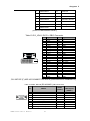
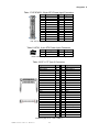
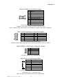
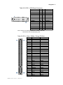
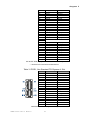
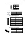
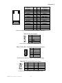
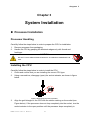
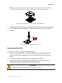
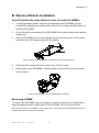
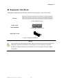
1
KEMX-4060 Industrial Motherboard in Mini-ITX form factor with Intel® GM45/ ICH9M User’s Guide KEMX-4060 User’s Manual I Contact Info: Quanmax Inc. 5F, No. 415, Ti-Ding Blvd. Sec. 2, NeiHu District, Taipei, Taiwan 114 Tel: +886-2-2799-2789 Fax: +886-2-2799-7399 Visit our site at: www.quanmax.com © 2010 Quanmax Inc. All rights reserved. The information in this user’s guide is provided for reference only. Quanmax does not assume any liability arising out of the application or use of the information or products described herein. This user’s guide may contain or reference information and products protected by copyrights or patents and does not convey any license under the patent rights of Quanmax, nor the rights of others. Quanmax is a registered trademark of Quanmax. All trademarks, registered trademarks, and trade names used in this user’s guide are the property of their respective owners. All rights reserved. This user’s guide contains information proprietary to Quanmax. Customers may reprint and use this user’s guide in other publications. Customers may alter this user’s guide and publish it only after they remove the Quanmax name, cover, and logo. Quanmax reserves the right to make changes without notice in product or component design as warranted by evolution in user needs or progress in engineering or manufacturing technology. Changes which affect the operation of the unit will be documented in the next revision of this user’s guide. Revision Date Edited by Changes 1.0 01/04/2010 SLee Initial Release 1.01 01/18/2009 SLee ATXPWR1 & MPCIE1 Pin out modify 1.02 05/06/2010 Zack Update some descriptions 1.03 10/18/2010 Zack Update VGA 9 pin 1.04 01/29/2011 Zack Add remark on clear CMOS KEMX-4060 User’s Manual II th Content Content Content....................................................................................................................... 3 Figures ....................................................................................................................... 5 Tables ......................................................................................................................... 6 Safety Instructions ...................................................................................................... 8 Before You Begin...................................................................................... 8 When Working Inside a Computer ............................................................ 8 Preventing Electrostatic Discharge ........................................................... 9 Preface ..................................................................................................................... 10 How to Use This Guide........................................................................... 10 Unpacking .............................................................................................. 10 Regulatory Compliance Statements ....................................................... 10 Warranty Policy ...................................................................................... 11 Maintaining Your Computer .................................................................... 12 Chapter 1 Introduction ........................................................................................... 15 Overview ................................................................................................ 15 Product Specifications ............................................................................ 16 Comparison Chart .................................................................................. 17 System Block Diagram ........................................................................... 18 Mechanical Dimensions.......................................................................... 19 Chapter 2 Hardware Settings ................................................................................ 20 Overview ................................................................................................ 20 Jumper Settings and Pin Definitions....................................................... 21 Jumper Settings .............................................................................. 22 Rear Panel Pin Assignments ........................................................... 24 Main Board Pin Assignments ..................................................................... 27 Chapter 3 System Installation ................................................................................ 35 Processor Installation ............................................................................. 35 Processor Handling.................................................................................... 35 Installing the CPU ...................................................................................... 35 Removing the CPU: ................................................................................... 36 Cooler Installation ................................................................................... 37 Memory Module Installation.................................................................... 38 Expansion Interfaces .............................................................................. 39 Chapter 4 AMI BIOS Setup.................................................................................... 40 KEMX-4060 User’s Manual 3 Content Overview ................................................................................................ 40 Main Menu.............................................................................................. 41 Advanced Menu ..................................................................................... 42 Boot Menu .............................................................................................. 47 Chipset Menu ......................................................................................... 48 Power Menu ........................................................................................... 49 Security Menu ........................................................................................ 50 Exit Menu ............................................................................................... 51 Chapter 5 Driver Installation .................................................................................. 52 Appendix A DIO (Digital I/O) Sample Code .............................................................. 53 Appendix B WatchDog Timer Sample Code ............................................................ 55 KEMX-4060 User’s Manual 4 Figures Figures Figure 1 Block Diagram ............................................................................. 18 Figure 2 KEMX-4060 Mechanical Dimensions ........................................... 19 Figure 3 Jumper Connector ....................................................................... 20 Figure 4 KEMX-4060 Jumper and Connector Locations ............................ 21 Figure 5 Disengage the socket actuator .................................................... 35 Figure 6 CPU alignment in Micro-FCPGA Socket (Socket P) .................... 36 Figure 7 Secure the processor in the socket .............................................. 36 Figure 8 Align the SO-DIMM Memory Module with the onboard socket ..... 38 Figure 9 Press down on the SO-DIMM Memory Module ............................ 38 Figure 10 Expansion Interfaces ................................................................. 39 KEMX-4060 User’s Manual 5 Tables Tables Table 1 KEMX-4060 Specification .............................................................. 16 Table 2 Comparison Chart ......................................................................... 17 Table 3 Jumper List .................................................................................... 22 Table 4 JP1, Clear CMOS Selection .......................................................... 22 Table 5 JP13, JP14, JP7, JP2, COM1, 2, 3, 4 Port Signal / Power Selection ............................................................................................................ 22 Table 6 JP6, Blacklight & Panel Power Selection....................................... 23 Table 7 JP5, BL Signal Selection ............................................................... 23 Table 8 JP4, ATX/AT mode Selection ......................................................... 23 Table 9 JP15, Mini PCIE Revision Selection .............................................. 23 Table 10 AUDIO1, 3 Stack-up HD Audio Phone Jack................................. 24 Table 11 LAN1,LAN2, RJ-45 + 2 USB 2.0 Connector ................................ 24 Table 12 HDMI1, HDMI Connector............................................................. 24 Table 13 DVI_VGA1, DVI-D + DB15 Connector ......................................... 25 Table 14 COM1, RS-232 (RS-422/485**) DB-9 Connector ........................ 25 Table 15 COM2, RS-232 DB-9 Connector ................................................. 26 Table 16 Internal Connector List ................................................................ 27 Table 17 ATXPWR1, 24-pin ATX Power Input Connector........................... 28 Table 18 ATX1, 4-pin ATX Power Input Connector ..................................... 28 Table 19 CF1, CF Type II Connector .......................................................... 28 Table 20 COM3-10, RS-232 Pin Header .................................................... 29 Table 21 DIO1, Digital Input / Output Pin Header....................................... 29 Table 22 SPDIF1, SPD/IF Input / Output Pin Header ................................. 29 Table 23 CN1, Panel Backlight Wafer ........................................................ 29 Table 24 AMP_L1 , AMP_R1, 2W Audio AMP Output Wafer ...................... 30 Table 25 CD1, CD-ROM Audio Input Wafer ............................................... 30 Table 26 CPU_FAN1, CHA_FAN1, FAN Wafer .......................................... 30 Table 27 FP1, Front Panel 1 Pin Header ................................................... 30 Table 28 FP2, Front Panel 2 Pin Header ................................................... 30 Table 29 LVDS1, LVDS Panel Connector................................................... 31 Table 30 PCI1, 32-bit / 33Mhz / 5V-key PCI Slot ........................................ 31 Table 31 PCIE1, Non Standard PCI Express x1 Slot ................................. 32 Table 32 SATAII_1, SATAII_2, SATAII_3, Serial ATA Connector ................ 33 Table 33 USB1, USB2, USB3, USB2.0 Pin Header ................................... 33 KEMX-4060 User’s Manual 6 Tables Table 34 LPT1, Parallel Port DB-25 Connector .......................................... 33 Table 35 MPCIE1, Mini PCIe Connector .................................................... 33 Table 36 IR1 Pin Header ............................................................................ 34 Table 37 KB_MS1, Keyboard and mouse connector.................................. 34 Table 38 FP3, HD AUDIO Front Panel ....................................................... 34 Table 39 BIOS Main Menu ......................................................................... 41 Table 40 SATA and onboard CF Device Setting Menu ............................... 41 Table 41 System Information...................................................................... 42 Table 42 Advanced Menu ........................................................................... 42 Table 43 I/O Configuration ......................................................................... 43 Table 44 OnBoard Peripherals Configuration Settings .............................. 45 Table 45 Hardware Health Configuration ................................................... 46 Table 46 Boot Menu ................................................................................... 47 Table 47 Chipset Menu .............................................................................. 48 Table 48 Video Function Configuration ...................................................... 48 Table 49 Power Menu ................................................................................ 49 Table 50 Security Menu ............................................................................. 50 Table 51 Exit Menu .................................................................................... 51 KEMX-4060 User’s Manual 7 Safety Instructions Safety Instructions Before You Begin Before handling the product, read the instructions and safety guidelines on the following pages to prevent damage to the product and to ensure your own personal safety. Refer to the “Advisories” section in the Preface for advisory conventions used in this user’s guide, including the distinction between Warnings, Cautions, Important Notes, and Notes. Always use caution when handling/operating a computer. Only qualified, experienced, authorized electronics service personnel should access the interior of a computer. The power supplies produce high voltages and energy hazards, which can cause bodily harm. Use extreme caution when installing or removing components. Refer to the installation instructions in this user’s guide for precautions and procedures. If you have any questions, please contact Quanmax Post-Sales Technical Support. WARNING High voltages are present inside the chassis when the unit’s power cord is plugged into an electrical outlet. Turn off system power, turn off the power supply, and then disconnect the power cord from its source before removing the chassis cover. Turning off the system power switch does not remove power to components. When Working Inside a Computer Before taking covers off a computer, perform the following steps: 1. Turn off the computer and any peripherals. 2. Disconnect the computer and peripherals from their power sources or subsystems to prevent electric shock or system board damage. This does not apply when hot swapping parts. 3. Follow the guidelines provided in “Preventing Electrostatic Discharge” on the following page. KEMX-4060 User’s Manual 8 Safety Instructions 4. Disconnect any telephone or telecommunications lines from the computer. In addition, take note of these safety guidelines when appropriate: To help avoid possible damage to system boards, wait five seconds after turning off the computer before removing a component, removing a system board, or disconnecting a peripheral device from the computer. When you disconnect a cable, pull on its connector or on its strain-relief loop, not on the cable itself. Some cables have a connector with locking tabs. If you are disconnecting this type of cable, press in on the locking tabs before disconnecting the cable. As you pull connectors apart, keep them evenly aligned to avoid bending any connector pins. Also, before connecting a cable, make sure both connectors are correctly oriented and aligned. CAUTION Do not attempt to service the system yourself except as explained in this user’s guide. Follow installation and troubleshooting instructions closely. Preventing Electrostatic Discharge Static electricity can harm system boards. Perform service at an ESD workstation and follow proper ESD procedure to reduce the risk of damage to components. Quanmax strongly encourages you to follow proper ESD procedure, which can include wrist straps and smocks, when servicing equipment. You can also take the following steps to prevent damage from electrostatic discharge (ESD): When unpacking a static-sensitive component from its shipping carton, do not remove the component’s antistatic packing material until you are ready to install the component in a computer. Just before unwrapping the antistatic packaging, be sure you are at an ESD workstation or grounded. This will discharge any static electricity that may have built up in your body. When transporting a sensitive component, first place it in an antistatic container or packaging. Handle all sensitive components at an ESD workstation. If possible, use antistatic floor pads and workbench pads. Handle components and boards with care. Don’t touch the components or contacts on a board. Hold a board by its edges or by its metal mounting bracket. Do not handle or store system boards near strong electrostatic, electromagnetic, magnetic, or radioactive fields. KEMX-4060 User’s Manual 9 Preface Preface How to Use This Guide This guide is designed to be used as step-by-step instructions for installation, and as a reference for operation, troubleshooting, and upgrades. NOTE Driver downloads and additional information are available under Downloads on our web site: www.quanmax.com. Unpacking When unpacking, follow these steps: 1. After opening the box, save it and the packing material for possible future shipment. 2. Remove all items from the box. If any items listed on the purchase order are missing, notify Quanmax customer service immediately. 3. Inspect the product for damage. If there is damage, notify Quanmax customer service immediately. Refer to “Warranty Policy” for the return procedure. Regulatory Compliance Statements This section provides the FCC compliance statement for Class A devices. FCC Compliance Statement for Class A Devices The product(s) described in this user’s guide has been tested and found to comply with the limits for a Class A digital device, pursuant to Part 15 of the FCC Rules. These limits are designed to provide reasonable protection against harmful interference when the equipment is operated in a commercial environment. This equipment generates, uses, and can radiate radio frequency energy and, if not installed and used in accordance with the user’s guide, may cause harmful interference to radio communications. Operation of this equipment in a residential area (domestic environment) is likely to cause harmful interference, in which case KEMX-4060 User’s Manual 10 Preface the user will be required to correct the interference (take adequate measures) at their own expense. Changes or modifications not expressly approved by Quanmax could void the user's authority to operate the equipment. NOTE The assembler of a personal computer system may be required to test the system and/or make necessary modifications if a system is found to cause harmful interference or to be noncompliant with the appropriate standards for its intended use. Warranty Policy Limited Warranty Quanmax Inc.’s detailed Limited Warranty policy can be found under Support at www.quanmax.com. Please consult your distributor for warranty verification. The limited warranty is void if the product has been subjected to alteration, neglect, misuse, or abuse; if any repairs have been attempted by anyone other than Quanmax or its authorized agent; or if the failure is caused by accident, acts of God, or other causes beyond the control of Quanmax or the manufacturer. Neglect, misuse, and abuse shall include any installation, operation, or maintenance of the product other than in accordance with the user’s guide. No agent, dealer, distributor, service company, or other party is authorized to change, modify, or extend the terms of this Limited Warranty in any manner whatsoever. Quanmax reserves the right to make changes or improvements in any product without incurring any obligation to similarly alter products previously purchased. Return Procedure For any Limited Warranty return, please contact Support at www.quanmax.com and login to obtain a Return Material Authorization (RMA) Number. If you do not have an account, send an email to [email protected] to apply for one. All product(s) returned to Quanmax for service or credit must be accompanied by a Return Material Authorization (RMA) Number. Freight on all returned items must be prepaid by the customer who is responsible for any loss or damage caused by common carrier in transit. Returns for Warranty must include a Failure Report for each unit, by serial number(s), as well as a copy of the original invoice showing the date of purchase. To reduce risk of damage, returns of product must be in a Quanmax shipping container. If the original container has been lost or damaged, new shipping KEMX-4060 User’s Manual 11 Preface containers may be obtained from Quanmax Customer Service at a nominal cost. Quanmax owns all parts removed from repaired products. Quanmax uses new and reconditioned parts made by various manufacturers in performing warranty repairs and building replacement products. If Quanmax repairs or replaces a product, its warranty term is not extended. Shipments not in compliance with this Limited Warranty Return Policy will not be accepted by Quanmax. Limitation of Liability In no event shall Quanmax be liable for any defect in hardware, software, loss, or inadequacy of data of any kind, or for any direct, indirect, incidental, or consequential damages in connection with or arising out of the performance or use of any product furnished hereunder. Quanmax’s liability shall in no event exceed the purchase price of the product purchased hereunder. The foregoing limitation of liability shall be equally applicable to any service provided by Quanmax or its authorized agent. Maintaining Your Computer Environmental Factors Temperature The ambient temperature within an enclosure may be greater than room ambient temperature. Installation in an enclosure should be such that the amount of air flow required for safe operation is not compromised. Consideration should be given to the maximum rated ambient temperature. Overheating can cause a variety of problems, including premature aging and failure of chips or mechanical failure of devices. If the system has been exposed to abnormally cold temperatures, allow a two-hour warm-up period to bring it up to normal operating temperature before turning it on. Failure to do so may cause damage to internal components, particularly the hard disk drive. Humidity High-humidity can cause moisture to enter and accumulate in the system. This moisture can cause corrosion of internal components and degrade such properties as electrical resistance and thermal conductivity. Extreme moisture buildup inside the system can result in electrical shorts, which can cause serious damage to the system. Buildings in which climate is controlled usually maintain an acceptable level of humidity for system equipment. However, if a system is located in an unusually KEMX-4060 User’s Manual 12 Preface humid location, a dehumidifier can be used to maintain the humidity within an acceptable range. Refer to the “Specifications” section of this user’s guide for the operating and storage humidity specifications. Altitude Operating a system at a high altitude (low pressure) reduces the efficiency of the cooling fans to cool the system. This can cause electrical problems related to arcing and corona effects. This condition can also cause sealed components with internal pressure, such as electrolytic capacitors, to fail or perform at reduced efficiency. Power Protection The greatest threats to a system’s supply of power are power loss, power spikes, and power surges caused by electrical storms, which interrupt system operation and/or damage system components. To protect your system, always properly ground power cables and one of the following devices. Surge Protector Surge protectors are available in a variety of types and usually provide a level of protection proportional with the cost of the device. Surge protectors prevent voltage spikes from entering a system through the AC power cord. Surge protectors, however, do not offer protection against brownouts, which occur when the voltage drops more than 20 percent below the normal AC line voltage level. Line Conditioner Line conditioners go beyond the over voltage protection of surge protectors. Line conditioners keep a system’s AC power source voltage at a fairly constant level and, therefore, can handle brownouts. Because of this added protection, line conditioners cost more than surge protectors. However, line conditioners cannot protect against a complete loss of power. Uninterruptible Power Supply Uninterruptible power supply (UPS) systems offer the most complete protection against variations on power because they use battery power to keep the server running when AC power is lost. The battery is charged by the AC power while it is available, so when AC power is lost, the battery can provide power to the system for a limited amount of time, depending on the UPS system. UPS systems range in price from a few hundred dollars to several thousand dollars, with the more expensive unit s allowing you to run larger systems for a longer period of time when AC power is lost. UPS systems that provide only 5 minutes of battery power let you conduct an orderly shutdown of the system, KEMX-4060 User’s Manual 13 Preface but are not intended to provide continued operation. Surge protectors should be used with all UPS systems, and the UPS system should be Underwriters Laboratories (UL) safety approved. KEMX-4060 User’s Manual 14 Chapter 1 Chapter 1 Introduction Overview The new KEMX-4060 is a Mini-ITX form factor industrial motherboard combining the high performance Intel® Core 2 Duo 45nm processor with the high integration of the Intel® GM45/ ICH9M chipset. Featured are two DDR3-800/1066 SO-DIMM up to 8GB, Mobile Intel® Graphics Media Accelerator 4500MHD supports DirectX 10, MPEG2, WMV9(VC-1), H.264(AVC), 18/ 24-bit dual-channel LVDS, DVI-D, HDMI, Gigabit Ethernet, SATA 3 Gb/s, mini PCIe expansion slot, CF, 11x USB 2.0, 10x COM ports with voltage support HD audio, and keyboard/mouse. The KEMX-4060 is a compact, high performance industrial motherboard that is ideal for multimedia, gaming, digital signage and medical applications. Checklist 1x KEMX-4060 Series mini-ITX motherboard 1x SATA cable 1x COM port cable 1x PS2 cable 1x I/O shield 1x Driver/ Manual CD 1x Quick Installation Guide Features Intel® Core 2 Duo 45nm processor support Intel® GM45/ ICH9M chipset Mobile Intel® GMA 4500MHD supports DirectX 10, MPEG2, WMV9, and H.264 VGA, DVI-D, HDMI, 18/24-bits dual channel LVDS Two DDR3 SO-DIMMs up to 8GB 3x SATA 3 Gb/s, CF socket,1x mini PCIex1 slot, 1x PCIe x1 slot (w/ 3x PCIe x1 speed) 2 x GbEs, 11x USB2.0, 10x COMs, 1 x LPT, HD audio with 2W amplifier onboard Watchdog Timer, Hardware Monitor KEMX-4060 User’s Manual 15 Chapter 1 Product Specifications CPU Support Intel® Core 2 Duo (Socket P, Penryn Core) Chipset Intel® GM45 +ICH9M Memory 2x DDR3 800/1066 SO-DIMM Socket, up to 8GB BIOS AMI PnP Flash BIOS Display Mobile Intel® Graphics Media Accelerator 4500MHD 18/24-bit dual-channel LVDS 1x HDMI 1x DVI-D 1x VGA LAN 2x RJ-45, Gigabit Ethernet Audio Peripheral Support Power Connector Expansion HD Audio Codec, supports Line-in, Line-out & Mic-in Onboard 2W audio amplifier 1x wafer connector for CD-In S/PDIF support One 2x5-pins HD front panel audio support 1x CompactFlash socket 3x SATA 3Gb/s 10x COMs (KEMX-4060), 6x COMs (KEMX-4062) 2x DB-9 male connectors for COM1/2 RS422/485 supports on COM1 COM1 to 4 with +12V & +5V @ 1A support, select by jumper 8x headers for COM3 to 10 (KEMX-4060) 4x headers for COM3 to 6 (KEMX-4062) 11x USB 2.0 (4x connector+ 6x pin header +1 support by mini PCIe slot) 1x Parallel port (Pin Header) 1x IrDA (Pin Header) 1x Wafer connector for keyboard and mouse 4x DI/DO TPM 1.2 support (optional) 1x ATX-24P for power input 1x ATX-4P for CPU core power AT/ATX supported 1x mini PCIex1 slot 1x PCIe riser for 3x PCIe x1 1x PCI slot with 2 x PCI master supported Watchdog Timer 1-255 step Hardware Monitor Operating voltage, CPU temperature and fan speed Dimensions Mini-ITX (170 x 170 mm) Environmental Factors Operation Temp: 0ºC - 60ºC Storage Temp.: -10ºC - 85ºC Humidity: 0% - 90% Certifications CE, FCC Class A Table 1 KEMX-4060 Specification KEMX-4060 User’s Manual 16 Chapter 1 Comparison Chart Model Name KEMX-4060 PCB Layers 6 45nm Penryn Socket P CPUs 6 45nm Penryn Socket P CPUs GM45 / ICH9M GM45 / ICH9M 2 x SO-DIMM DDR3 Yes 18/24-bits Yes Yes 2 x SO-DIMM DDR3 Yes 18/24-bits Yes Yes Yes Yes 2 x GbE 2 x GbE Yes Yes 3 1 11 10 3 1 11 6 4 4 Yes 1 Yes 1 Yes Yes Yes Yes PCI Master Mini PCIE WatchDog 4-bits input / 4-bits Output 2 1 Yes 4-bits input / 4-bits Output 2 1 Yes AT Power Support Yes Yes CPU Chipset Memory VGA LVDS DVI-D HDMI LCD Back Light Control Ethernet Audio with 2W amplifier SATA Compact Flash USB 2.0 Port COM Port COM Port with Voltage Support RS-422/485 LPT Port PS/2 Keyboard PS/2 Mouse Digital I/O Table 2 Comparison Chart KEMX-4060 User’s Manual 17 KEMX-4062 Chapter 1 System Block Diagram Figure 1 Block Diagram KEMX-4060 User’s Manual 18 Chapter 1 Mechanical Dimensions Figure 2 KEMX-4060 Mechanical Dimensions KEMX-4060 User’s Manual 19 Chapter 2 Chapter 2 Hardware Settings Overview This chapter provides the definitions and locations of jumpers, headers, and connectors. Jumpers The product has several jumpers which must be properly configured to ensure correct operation. Figure 3 Jumper Connector For a three-pin jumper (see Figure 3), the jumper setting is designated “1-2” when the jumper connects pins 1 and 2. The jumper setting is designated “2-3” when pins 2 and 3 are connected and so on. You will see that one of the lines surrounding a jumper pin is thick, which indicates pin No.1. To move a jumper from one position to another, use needle-nose pliers or tweezers to pull the pin cap off the pins and move it to the desired position. KEMX-4060 User’s Manual 20 Chapter 2 Jumper Settings and Pin Definitions For jumper and connector locations, please refer to the diagrams below. Figure 4 KEMX-4060 Jumper and Connector Locations KEMX-4060 User’s Manual 21 Chapter 2 Jumper Settings To ensure correct system configuration, the following section describes how to set the jumpers to enable/disable or change functions. For jumper descriptions, please refer to the table below. Table 3 Jumper List Label Function JP1 Clear CMOS Selection JP13 COM1 Signal / Power Selection JP14 COM2 Signal / Power Selection JP7 COM3 Signal / Power Selection JP2 COM4 Signal / Power Selection JP6 Panel & Backlight Power Selection JP5 BL Signal Selection JP4 ATX/AT mode Selection JP15 MPCIE Rev select Table 4 JP1, Clear CMOS Selection Jumper Status Open Normal Operation (default) Short Clear CMOS Pitch: 2.54mm [YIMTEX 3321*02SAGR(6T)] Remark: You must go to BIOS EXIT menu to do “Load Optimal Defaults” after clear CMOS. Please refer to table 51. Table 5 JP13, JP14, JP7, JP2, COM1, 2, 3, 4 Port Signal / Power Selection Jumper 1 Setting Function 1-3 Short Pin 1 = +12V 3-5 Short Pin 1 = +5V 5-7 Short Pin 1 = +5V 7-9 Short Pin 1 = DCD@RS232, TX-@RS422, DATA-@RS485(Half Duplex) (default) 2-4 Short Pin 9 = +12V 4-6 Short Pin 9 = +5V 6-8 Short Pin 9 = +5V 8-10 Short Pin 9 = RI (default) 2 JP2,JP7,JP13,JP14 : Pitch:2.54mm [YIMTEX 3322*05SAGR(6T] LEAD FREE KEMX-4060 User’s Manual 22 Chapter 2 Table 6 JP6, Blacklight & Panel Power Selection Jumper Setting Status 1-3 Backlight Power = +12V (default) 3-5 Backlight Power = +5V 2-4 Panel Power = +3.3V (default) 4-6 Panel Power = +5V 1 2 Pitch:2.54mm [YIMTEX 3362*03SAGR] Table 7 JP5, BL Signal Selection Jumper Status 1-2 High Active (default) 2-3 Low Active TYPE Pitch:2.0mm [YIMTEX 3291*03SAGR(6T)] Table 8 JP4, ATX/AT mode Selection Jumper Status Open ATX mode(default) Short AT mode Pitch:2.0mm [YIMTEX 3291*02SAGR(6T)] Table 9 JP15, Mini PCIE Revision Selection Jumper Status 1-2 MPCIE Rev1.1 (default) 2-3 MPCIE Rev1.2 PIN HEADER,DIP 3P 1R MALE STRAIGHT TYPE Pitch:2.54mm [YIMTEX 3321*03SAGR(6T)] LEAD FREE KEMX-4060 User’s Manual 23 Chapter 2 Rear Panel Pin Assignments Table 10 AUDIO1, 3 Stack-up HD Audio Phone Jack Signal Name BLUE LINE IN GREEN LINE OUT PINK MIC IN AUDIO JACK*3 DIP Vertical [Foxconn JA33331-H11P-4F] *Support Jack re-tasking & multi-streaming Table 11 LAN1,LAN2, RJ-45 + 2 USB 2.0 Connector Pin L1 L2 L3 L4 L5 L6 L7 L8 L9 L10 L11 Signal VCC MDI[0]+ MDI[0]MDI[1]+ MDI[1]MDI[2]+ MDI[2]MDI[3]+ MDI[3]GND YLED- Pin L12 L13 L14 U1 U2 U3 U4 U5 U6 U7 U8 Signal YLED+ GLEDGLED+ +5VSV USB_AUSB_A+ GND +5VSB USB_BUSB_B+ GND [UDE RU1-161F9WGF(XB)] Table 12 HDMI1, HDMI Connector KEMX-4060 User’s Manual Pin Signal Pin Signal 1 TMDS Data2+ 11 TMDS Clock Shield 2 TMDS Data2 Shield 12 TMDS Clock– 3 TMDS Data2– 13 CEC 24 Chapter 2 4 TMDS Data1+ 14 Reserved 5 TMDS Data1 Shield 15 SCL 6 TMDS Data1– 16 SDA 7 TMDS Data0+ 17 DDC/CEC Ground 8 TMDS Data0 Shield 18 +5 V Power 9 TMDS Data0– 19 Hot Plug Detect 10 TMDS Clock+ [KUON YI HDMI-KRPS00-A03N2-L] Table 13 DVI_VGA1, DVI-D + DB15 Connector Pin 1 2 3 4 5 6 7 8 9 10 11 12 13 14 15 16 17 18 19 20 21 22 23 24 Signal Tx2Tx2+ GND TX4TX4+ DDC_CLK DDC_DATA CRT_VSYNC TX1TX1+ GND TX3TX3+ +5V GND HTPLG TX0TX0+ GND TX5TX5+ GND TXC+ TXC- Pin V1 V2 V3 V4 V5 V6 V7 V8 V9 V10 V11 V12 V13 V14 V15 V16 V17 Signal R G B NC GND VGA_EN GND GND NC GND NC SD_DATA CRT_HSYNC CRT_VSYNC SD_CLK GND GND 25 26 GND GND ,DVI 29P DIP (F) 90D H/D CONNECTOR WHITE [WIN WIN WDVI-29ABNW11U] Table 14 COM1, RS-232 (RS-422/485**) DB-9 Connector Pin RS232 RS422 (COM1*) 1 2 3 4 5 6 7 8 9 DCD, Data carrier detect RXD, Receive data TXD, Transmit data DTR, Data terminal ready GND, ground DSR, Data set ready RTS, Request to send CTS, Clear to send RI, Ring indicator (+5V / +12V *) TXRX+ TX+ RXGND N/A N/A N/A N/A KEMX-4060 User’s Manual 25 RS485 Half Duplex (COM1*) DATAN/A DATA+ N/A GND N/A N/A N/A N/A Chapter 2 * The function can be selected by JP13 ** The RS-232/422/485 function can be selected from BIOS setting. Table 15 COM2, RS-232 DB-9 Connector Pin 1 2 3 4 9 Signal Pin DCD, Data carrier detect 5 RXD, Receive data 6 TXD, Transmit data 7 DTR, Data terminal ready 8 RI, Ring indicator (+5V / +12V *) Signal GND, ground DSR, Data set ready RTS, Request to send CTS, Clear to send * The function can be selected from by JP14 KEMX-4060 User’s Manual 26 Chapter 2 Main Board Pin Assignments Table 16 Internal Connector List Label Function ATXPWR1 24-pin ATX Power Input Connector ATX1 4-pin ATX Power Input Connector CF1 CF Type II Connector COM3 RS-232 Port 3 Pin Header COM4 RS-232 Port 4 Pin Header COM5 RS-232 Port 5 Pin Header COM6 RS-232 Port 6 Pin Header COM7 RS-232 Port 7 Pin Header COM8 RS-232 Port 8 Pin Header COM9 RS-232 Port 9 Pin Header COM10 RS-232 Port 10 Pin Header DIO1 Digital Input / Output Pin Header SPDIF1 SPD/IF Output Pin Header CN1 Panel Backlight Wafer AMP_L1 Left Channel 2W Audio AMP Output Wafer AMP_R1 Right Channel 2W Audio AMP Output Wafer CD1 CD-ROM Audio Input Wafer DDR3_1 Primary DDR3 Memory DIMM Slot DDR3_2 Secondary DDR3 Memory DIMM Slot CPU_FAN1 CPU FAN Wafer CHA_FAN1 System FAN Wafer FP1 Front Panel 1 Pin Header FP2 Front Panel 2 Pin Header LVDS1 LVDS Panel Connector PCI1 32-bit / 33Mhz / 5V-key PCI Slot PCIE1 None Standard PCI Express x1 Slot SATAII_1 Serial ATA Connector SATAII_2 Serial ATA Connector SATAII_3 Serial ATA Connector USB1 USB2.0 Port 4, 5 Pin Header USB2 USB2.0 Port 6, 7 Pin Header USB3 USB2.0 Port 8, 9 Pin Header KB_MS1 KB/MS BOX Header FP3 HD AUDIO Front Panel LPT1 Parallel Port Pin Header MPCIE1 Mini PCIe Connector IR1 IrDA Pin Header KEMX-4060 User’s Manual 27 Chapter 2 Table 17 ATXPWR1, 24-pin ATX Power Input Connector Pin 1 2 3 4 5 6 7 8 9 10 11 12 Signal +3.3V +3.3V GND +5V GND +5V GND POWER OK +5VSB +12V +12V +3.3V Pin 13 14 15 16 17 18 19 20 21 22 23 24 Signal +3.3V -12V GND PS_ON GND GND GND NC +5V +5V +5V GND DIP 12P*2.180D(M) [YIMTEX 576MWA2*12STR] Table 18 ATX1, 4-pin ATX Power Input Connector Pin 1 3 Signal GND +12V Pin 2 4 Signal GND +12V Pitch:4.2mm PIN [YIMTEX 576MWA2*02STR] Table 19 CF1, CF Type II Connector Signal Name GND IDE Data 3 IDE Data 4 IDE Data 5 IDE Data 6 IDE Data 7 IDE Chip select 1# GND GND GND GND GND +5V GND GND GND GND SDA2 IDE Address 1 IDE Address 0 IDE Data 0 IDE Data 1 IDE Data 2 IOIS16# GND Pin 1 2 3 4 5 6 7 8 9 10 11 12 13 14 15 16 17 18 19 20 21 22 23 24 25 Pin 26 27 28 29 30 31 32 33 34 35 36 37 38 39 40 41 42 43 44 45 46 47 48 49 50 Standard type[ CF1A-71041-00E01] KEMX-4060 User’s Manual 28 Signal Name GND IDE Data 11 IDE Data 12 IDE Data 13 IDE Data 14 IDE Data 15 IDE Chip select 3# GND IDEIOR# IDEIOW# +5V IDEIRQ +5V PCSEL NC Reset IDE IDEIORDY DREQ DACK# IDE activity PDIAG# IDE Data 8 IDE Data 9 IDE Data 10 GND Chapter 2 Table 20 COM3-10, RS-232 Pin Header Pin 1 2 3 4 5 6 7 8 9 10 Signal DCD, Data carrier detect RXD, Receive data TXD, Transmit data DTR, Data terminal ready GND, ground DSR, Data set ready RTS, Request to send CTS, Clear to send RI, Ring indicator* NC Pitch:2.54mm [PINREX 210-92-05GB02] * COM3 to 4 with +12V & +5V @ 1A support, select by jumper Cable : COM Port cable, pitch 2.54mm 10P, D-SUB 9P, L=250mm, with bracket, 180degree, Table 21 DIO1, Digital Input / Output Pin Header Pin 1 3 5 7 9 Signal Digital Output 0 Digital Output 1 Digital Output 2 Digital Output 3 +VIO Pin 2 4 6 8 10 Signal Digital Input 0 Digital Input 1 Digital Input 2 Digital Input 3 GND Pitch:2.0mm [YIMTEX 3292*05SAGR(6T)] Cable: DIO Cable, DB9 Female connector to 2x5-pin pitch:2.0mm connector, L=30cm Table 22 SPDIF1, SPD/IF Input / Output Pin Header Pin 1 2 3 4 Signal Name SPDIF_IN GND SPDIF_OUT GND P-2.54mm [YIMTEX 3321*04SAGR(6T)] Table 23 CN1, Panel Backlight Wafer Pin Signal Name BL_EN* GND +5V / +12V ** +5V / +12V ** GND BL_ADJ NC 1 2 3 4 5 6 7 P-1.25mm WAFER [YIMTEX 501MW1*07STR] *:Selected by JP5, **:Selected by JP6 Note:BL_ADJ can be setting from 0V to 5V in BIOS setup. KEMX-4060 User’s Manual 29 Chapter 2 Table 24 AMP_L1 , AMP_R1, 2W Audio AMP Output Wafer Pin Signal Name 1 Speaker+ 2 SpeakerPitch=2.0mm WAFER [YIMTEX 503PW1*02STR] Table 25 CD1, CD-ROM Audio Input Wafer Pin 1 2 3 4 Signal Name CD-IN-R GND GND CD-IN-L P-2.54mm WAFER [YIMTEX 522CW4SGR] Table 26 CPU_FAN1, CHA_FAN1, FAN Wafer Pin 1 2 3 Signal GND +12V FAN_RPM P-2.54mm WAFER [YIMTEX 521AW1*03STR] Table 27 FP1, Front Panel 1 Pin Header Pin 1 3 5 7 Signal Reset Button + Reset Button HDD LED + HDD LED - Pin 2 4 6 8 Signal Speaker + NC Internal SpeakerSpeaker - Pitch:2.54mm [YIMTEX 3322*04SAGR(6T)] Note:Internal Buzzer is enabled when Pin6-8 is shorted. Table 28 FP2, Front Panel 2 Pin Header Pin 1 3 5 7 9 Signal Power LED + NC Power LED Keyboard Lock GND Pin 2 4 6 8 10 Pitch:2.54mm [YIMTEX 3322*05SAGR(6T] KEMX-4060 User’s Manual 30 Signal Power Button + Power Button NC SMBus Data SMBus Clock Chapter 2 Table 29 LVDS1, LVDS Panel Connector Signal Name NC +3.3V / +5V* TxclkBTxclkB+ GND TxoutB0TxoutB0+ TxoutB1TxoutB1+ TxoutB2TxoutB2+ TxoutB3TxoutB3+ GND I2C_Clock Pin 2 4 6 8 10 12 14 16 18 20 22 24 26 28 30 Pin 1 3 5 7 9 11 13 15 17 19 21 23 25 27 29 Pitch:1.25mm Tin Plated [HIROSE DF13-30DP-1.25(24)] * this function can be selected by JP6 Table 30 PCI1, 32-bit / 33Mhz / 5V-key PCI Slot Pin 1 2 3 4 5 6 7 8 9 10 11 12 13 14 15 16 17 18 19 20 21 22 23 24 25 26 27 28 29 30 31 32 KEMX-4060 User’s Manual Side B -12V Reserved Ground Reserved +5V +5V INTB# INTD# Reserved REQ1# * Reserved Ground Ground CLK1 * Ground CLK0 Ground REQ0# +5V AD[31] AD[29] Ground AD[27] AD[25] +3.3V C/BE[3]# AD[23] Ground AD[21] AD[19] +3.3V AD[17] 31 Side A Reserved +12V Reserved Reserved +5V INTA# INTC# +5V GNT1# * +5V IDSEL1 * Ground Ground +3.3VAUX RST# +5V GNT0# Ground PME# AD[30] +3.3V AD[28] AD[26] Ground AD[24] IDSEL0 +3.3V AD[22] AD[20] Ground AD[18] AD[16] Signal Name NC +3.3V / +5V* TxclkATxclkA+ GND TxoutA0TxoutA0+ TxoutA1TxoutA1+ TxoutA2TxoutA2+ TxoutA3TxoutA3+ GND I2C_Data Chapter 2 33 34 35 36 37 38 39 40 41 42 43 44 45 46 47 48 49 50 51 52 53 54 55 56 57 58 59 60 61 62 PCI 60*2P 180D (F) C/BE[2]# Ground IRDY# +3.3V DEVSEL# Ground LOCK# PERR# +3.3V SERR# +3.3V C/BE[1]# AD[14] Ground AD[12] AD[10] Ground +3.3V FRAME# Ground TRDY# Ground STOP# +3.3V SMB_CLK SMB_DAT Ground PAR AD[15] +3.3V AD[13] AD[11] Ground AD[09] KEY AD[08] AD[07] +3.3V AD[05] AD[03] Ground AD[01] +5V Reserved +5V +5V C/BE[0]# +3.3V AD[06] AD[04] Ground AD[02] AD[00] +5V Reserved +5V +5V [FOXCONN EH06001-DAW-DF] *:Reserved for second PCI master device. Table 31 PCIE1, Non Standard PCI Express x1 Slot Pin 1 2 3 4 5 6 7 8 9 10 11 12 13 14 15 16 17 18 Side B +12V +12V +3.3VAUX WAKE# RST# Ground PETp0 PETn0 Ground PETp1 PETn1 SMB_CLK Ground PETp2 PETn2 Ground NC NC WPES-036AN3B22UWS [TECHBEST] KEMX-4060 User’s Manual 32 Side A +3.3V +3.3V Ground REFCLK+ REFCLKGround PERp0 PERn0 Ground PERp1 PERn1 SMB_DAT Ground PERp2 PERn2 Ground NC NC Chapter 2 Table 32 SATAII_1, SATAII_2, SATAII_3, Serial ATA Connector Pin 1 2 3 4 5 6 7 Signal Name GND TX+ TXGND RXRX+ GND [FOXCONN LD1807V-S52U] Table 33 USB1, USB2, USB3, USB2.0 Pin Header Pin 1 3 5 7 9 Signal Name +5V USB_AUSB_A+ GND KEY Pin 2 4 6 8 10 Signal Name +5V USB_BUSB_B+ GND GND Pitch: 2.54mm [YIMTEX 3322*05SAGR(6T) -09] Table 34 LPT1, Parallel Port DB-25 Connector Signal Line printer strobe PD0, parallel data 0 PD1, parallel data 1 PD2, parallel data 2 PD3, parallel data 3 PD4, parallel data 4 PD5, parallel data 5 PD6, parallel data 6 PD7, parallel data 7 ACK, acknowledge Busy Paper empty Select Pin 1 3 5 7 9 11 13 15 17 19 21 23 25 Pin 2 4 6 8 10 12 14 16 18 20 22 24 Signal AutoFeed Error Initialize Select In Ground Ground Ground Ground Ground Ground Ground Ground Pitch:2.54mm [PINREX 210-72-13GB11] Table 35 MPCIE1, Mini PCIe Connector KEMX-4060 User’s Manual Signal WAKE# Reserved Reserved Pin 1 3 5 Pin 2 4 6 Signal +3.3V_MPCIE Ground +1.5V Reserved 7 8 Reserved Ground 9 10 Reserved REFCLK- 11 12 Reserved REFCLK+ 13 14 Reserved 33 Chapter 2 Ground 15 16 Reserved Reserved Ground PERn0 PERp0 Ground Ground PETn0 PETp0 Ground Reserved +3.3VSB +3.3VSB Reserved Reserved Reserved Reserved Reserved 17 19 21 23 25 27 29 31 33 35 37 39 41 43 45 47 49 51 18 20 22 24 26 28 30 32 34 36 38 40 42 44 46 48 50 52 Reserved Ground W_disable# PERST# +3VSB Ground +1.5V SMB_CLK SMB_DATA Ground USB_DUSB_D+ Ground Reserved Reserved Reserved +1.5V Ground +3.3V MINI PCI-Express Connector [FOXCONN AS0B226-S56N-7F] Table 36 IR1 Pin Header Pin 1 2 3 4 5 Signal Name +5V Key RXD GND TXD Pitch:2.54mm [YIMTEX 3321*05SAGR(6T)-02] Table 37 KB_MS1, Keyboard and mouse connector Pin 1 2 3 4 5 6 Signal MS_CLK +5V MS_DATA KB_DAT GND KB_CLK WAFER DIP 6P MALE 1R 180D P=2.0mm [STM M24266] Table 38 FP3, HD AUDIO Front Panel Pin 1 3 5 7 9 Signal MIC2_L MIC2_R LIN2_R SENSE LIN2_L Pin 2 4 6 8 10 Signal AGND ACZ_DET MIC2_JD NC LINE2_JD P-2.54mm w/o Pin 8 [YIMTEX 3322*05SAGR(6T)-08] KEMX-4060 User’s Manual 34 Chapter 3 Chapter 3 System Installation Processor Installation Processor Handling Carefully follow the steps below in order to prepare the CPU for installation: 1. Remove processor from packaging. 2. Handle the CPU by grasping the substrate edges only with thumb and forefinger. CAUTION DO NOT TOUCH PROCESSOR CONTACTS TO PREVENT DAMAGING THE CPU. Installing the CPU Carefully follow the steps below in order to install the CPU: 1. Check and confirm that you are installing the correct CPU type. 2. Using a screwdriver, disengage (open) the socket actuator, as shown in figure below. Figure 5 Disengage the socket actuator 3. Align the gold triangle on the CPU with the similar marking on the socket (see Figure below). If the processor does not drop completely into the socket, turn the socket actuator to the open position until the processor drops completely in. KEMX-4060 User’s Manual 35 Chapter 3 Note: You should not have to press down on the processor. If the processor does not drop completely into the socket, turn the actuator until the processor drops completely in. Figure 6 CPU alignment in Micro-FCPGA Socket (Socket P) 4. While gently holding the processor down with your finger, secure the processor in the socket with a screwdriver by turning the socket actuator to the closed position: Figure 7 Secure the processor in the socket Removing the CPU: To remove the CPU, reverse the installation steps. 1. Before removing the CPU, turn off the system power and wait for about 20 minutes until the heat radiation plate of the cooling fan and the CPU cools down. 2. To remove the CPU, follow Step 2 of Installing the CPU above. 3. Remove the CPU by grasping the substrate edges only with thumb and forefinger and lifting it out with a purely vertical motion. WARNING The CPU and the heatsink may be hot and could cause burns. KEMX-4060 User’s Manual 36 Chapter 3 Cooler Installation The system must not be operated without a cooler (heat sink and fan) to provide the necessarily cooling. Install the cooling unit supplied as follows: CAUTION Make sure that good thermal contact is made between the processor and heat sink. Insufficient contact or incorrect use of heat sink, fan, or thermal compound can cause the processor to overheat, which may crash the system or cause permanent damage to the CPU. 1. 2. 3. Install the correct CPU as described above. Align the screw holes of the heatsink rear retention bracket with the mounting holes on the underside of the motherboard, located at the four corners of the CPU location. Insert into the holes and turn the motherboard over. Place the heatsink/fan assembly on top of the CPU with the cooling fins aligned with the Northbridge heatsink cooling fins. This will allow the fan to provide cooling the Northbridge. Align the screws with the screw holes of the rear retention bracket. NOTE Be careful not to touch the thermal pad on the underside of the heatsink. This pad is made of thermal compound and is deformable. It is designed to make optimal thermal contact with the CPU. No additional thermal compound is required. 4. Tighten each screw halfway to secure the cooler assembly to the motherboard. Then gradually tighten all four screws. Do not fully tighten the first screw before partially tightening the other screws as this may apply uneven pressure to the CPU, causing damage. NOTE In order to operate the KEMX-4060 without a fan, the cooling solution must be integrally designed with the chassis. Contact Quanmax for more information on fan less operation. KEMX-4060 User’s Manual 37 Chapter 3 Memory Module Installation Carefully follow the steps below in order to install the DIMMs: 1. 2. 3. To avoid generating static electricity and damaging the SO-DIMM, ground yourself by touching a grounded metal surface or use a ground strap before you touch the SO-DIMM. Do not touch the connectors of the SO-DIMM. Dirt or other residue may cause a malfunction. Hold the SO-DIMM with its notch aligned with the memory socket of the board and insert it at a 30-degree angle into the socket. Figure 8 Align the SO-DIMM Memory Module with the onboard socket 4. 5. Fully insert the module into the socket until a “click” is heard. Press down on the SO-DIMM so that the tabs of the socket lock on both sides of the module Figure 9 Press down on the SO-DIMM Memory Module Removing a DIMM: To remove the SO-DIMM, use your fingers or a small screwdriver to carefully push away the tabs that secure either side of the SO-DIMM. Lift it out of the socket. Make sure you store the SO-DIMM in an anti-static bag. The socket must be populated with memory modules of the same size and manufacturer. KEMX-4060 User’s Manual 38 Chapter 3 Expansion Interfaces The board comes with one PCI slot, one PCIe x1 slot and 1x mini PCIex1 slot. PCI slot 32-bit, 33MHz PCI slot PCIe x1 slot (non standard) 1x PCIe riser for 3x PCIe x1 mini PCIe x1 slot Figure 10 Expansion Interfaces NOTE When adding or removing expansion cards, make sure that you unplug the power supply first. Meanwhile, read the documentation for the expansion card to configure any necessary hardware or software settings for the expansion card, such as jumpers, switches or BIOS configuration. KEMX-4060 User’s Manual 39 Chapter 4 Chapter 4 AMI BIOS Setup Overview This chapter provides a description of the AMI BIOS. The BIOS setup menus and available selections may vary from those of your product. For specific information on the BIOS for your product, please contact Quanmax. NOTE: The BIOS menus and selections for your product may vary from those in this chapter. For the BIOS manual specific to your product, please contact Quanmax. AMI's ROM BIOS provides a built-in Setup program, which allows the user to modify the basic system configuration and hardware parameters. The modified data will be stored in a battery-backed CMOS, so that data will be retained even when the power is turned off. In general, the information saved in the CMOS RAM will not need to be changed unless there is a configuration change in the system, such as a hard drive replacement or when a device is added. It is possible for the CMOS battery to fail, which will cause data loss in the CMOS only. If this happens you will need to reconfigure your BIOS settings. KEMX-4060 User’s Manual 40 Chapter 4 Main Menu The BIOS Setup is accessed by pressing the DEL key after the Power-On Self-Test (POST) memory test begins and before the operating system boot begins. Once you enter the BIOS Setup Utility, the Main Menu will appear on the screen. The Main Menu provides System Overview information and allows you to set the System Time and Date. Use the “<” and “>” cursor keys to navigate between menu screens. Table 39 BIOS Main Menu BIOS SETUP UTILITY Main Advanced Boot Chipset System Date System Time [Thu 12/24/2009] [10:18:15] > SATA1 > SATA2 > SATA3 > CF :[Maxtor 6V160E0] :[Not Detected] :[Not Detected] :[Not Detected] Power Security Exit Use [ENTER], [TAB] or [SHIFT-TAB] to select a field. Use [+] or [-] to configure system Time. > System Information <> Select Screen ↑↓ Select Item +- Change Field Tab Select Field F1 General Help F10 Save and Exit ESC Exit V02.61 (C)Copyright 1985-2006, American Megatrends, Inc. Below table is described for SATA1-3 and onboard CF setting. Table 40 SATA and onboard CF Device Setting Menu BIOS SETUP UTILITY Main Advanced SATA1 Device Vendor Size LBA Mode Block Mode PIO Mode Async DMA Ultra DMA S.M.A.R.T. LBA/ Large Mode DMA Mode S.M.A.R.T Boot Chipset Power Security Exit Select the type of device :Hard Disk :Maxtor 6V160E0 :160.0GB :Supported :16 Sectors :4 :MultiWord DMA-2 :Ultra DMA-6 :Supported connected to the system. <> Select Screen ↑↓ Select Item +- Change Field Tab Select Field F1 General Help F10 Save and Exit ESC Exit [Auto] [Auto] [Auto] V02.61 (C)Copyright 1985-2006, American Megatrends, Inc. LBA/ Large Mode [Auto] Enables or disables the LBA (Logical Block Addressing)/ Large mode. Setting to Auto enables the LBA mode if the device supports this mode, and if the device was KEMX-4060 User’s Manual 41 Chapter 4 not previously formatted with LBA mode disabled. Options: Disabled, Auto DMA Mode [Auto] Setup DMA Mode. S.M.A.R.T [Auto] SMART stands for Smart Monitoring, Analysis, and Reporting Technology. It allows AMIBIOS to use the SMART protocol to report server system information over a network. Options: Auto, Disabled, Enabled Table 41 System Information BIOS SETUP UTILITY Main AMIBIOS Version Build Date Advanced Boot Chipset Power Security Exit : 1.0 :12/24/2009 Processor Intel(R) CPU (TM) 2 Duo T9400 @2.53GHz Speed :2533 MHz <> Select Screen ↑↓ Select Item +- Change Field Tab Select Field F1 General Help F10 Save and Exit ESC Exit Physical Memory Size :1024MB Speed :1067MHz V02.61 (C)Copyright 1985-2006, American Megatrends, Inc. Advanced Menu Table 42 Advanced Menu BIOS SETUP UTILITY Main Ad v a n c e d Boot Chipset Power Security Advanced Settings Warning: Setting wrong values in below sections may cause system to malfunction. <> Select Screen ↑↓ Select Item +- Change Field Tab Select Field F1 General Help F10 Save and Exit ESC Exit > I/O Configuration > OnBoard Peripherals Configuration > Hardware Health Configuration V02.61 (C)Copyright 1985-2006, American Megatrends, Inc. Press <Enter> to select a sub-menu for detailed options. KEMX-4060 User’s Manual 42 Exit Chapter 4 Table 43 I/O Configuration BIOS SETUP UTILITY Main Ad v a n c e d Boot Chipset Power Security Onboard I/O Configuration COM1 Address [3F8] COM1 IRQ [4] COM1 Function Type [RS232] COM2 Address [2F8] <> Select Screen COM2 IRQ [4] ↑↓ Select Item COM3 Address [3E8] +- Change Field COM3 IRQ [10] Tab Select Field COM4 Address [2E8] F1 General Help COM4 IRQ [11] F10 Save and Exit ESC Exit COM5 Address [2F0] COM5 IRQ [5] COM5 Mode [Normal] COM6 Address [2E0] COM6 IRQ [6] COM7 Address [2B0] COM7 IRQ [3] COM8 Address [2B8] COM8 IRQ [3] COM9 Address [2C0] COM9 IRQ [10] COM10 Address [2C8] COM10 IRQ [10] Parallel Port Address [378] Parallel Port Mode [Normal] Parallel Port IRQ [IRQ7] V02.61 (C)Copyright 1985-2006, American Megatrends, Inc. COM1 Address [3F8] Options: Disabled, 3F8, 3E8, 2E8 COM1 IRQ [4] Options: 3, 4, 10, 11 COM1 Function Type [RS232] Options: RS232, RS422, RS485 COM2 Address [2F8] Options: Disabled, 3F8, 3E8, 2E8 COM2 IRQ [4] Options: 3, 4, 10, 11 COM3 Address [3E8] Options: Disabled, 3F8, 3E8, 2E8 COM3 IRQ [10] Options: 3, 4, 10, 11 COM4 Address [2E8] Options: Disabled, 3F8, 2F8, 3E8, 2E8, 2F0, 2E0 COM4 IRQ [11] KEMX-4060 User’s Manual Exit Allows BIOS to Select Serial Port1 Base Addresses. 43 Chapter 4 Options: 3, 4, 10, 11 COM5 Address [2F0] Options: Disabled, 3F8, 2F8, 3E8, 2E8, 2F0, 2E0 COM5 IRQ [5] Options: 3, 4, 5, 6, 7, 10, 11 COM5 Mode [Normal] Options: Normal, IrDA, ASK IR COM6 Address [2E0] Options: Disabled, 3F8, 2F8, 3E8, 2E8, 2F0, 2E0 COM6 IRQ [6] Options: 3, 4, 5, 6, 7, 10, 11 COM7 Address [2B0] Options: Disabled, 2B0, 2B8, 2C0, 2C8, 2D0, 2D8 COM7 IRQ [3] Options: 3, 6, 7, 10 COM8 Address [2B8] Options: Disabled, 2B0, 2B8, 2C0, 2C8, 2D0, 2D8 COM8 IRQ [3] Options: 3, 6, 7, 10 COM9 Address [2C0] Options: Disabled, 2B0, 2B8, 2C0, 2C8, 2D0, 2D8 COM9 IRQ [10] Options: 3, 6, 7, 10 COM10 Address [2C8] Options: Disabled, 2B0, 2B8, 2C0, 2C8, 2D0, 2D8 COM10 IRQ [10] Options: 3, 6, 7, 10 Parallel Port Address [378] Options: Disabled, 378, 278, 3BC Parallel Port Mode [Normal] Options: Normal, EPP, ECP, EPP+ECP Parallel Port IRQ [IRQ7] Options: IRQ5, IRQ7 KEMX-4060 User’s Manual 44 Chapter 4 Table 44 OnBoard Peripherals Configuration Settings BIOS SETUP UTILITY Main Ad v a n c e d Boot Chipset OnBoard Peripherals Configuration Settings USB Functions [12 USB Ports] USB 2.0 Controller [Enable] Legacy USB Support [Enable] Audio Controller [Enable] Onboard LAN1 Controller [Enable] Onboard LAN2 Controller [Enable] Onboard LAN OPTROM [Disabled] Onboard Mini PCIE Controller [Enable] > On-Chip ATA Devices Power Security Exit Options Disabled 12 USB Ports <> Select Screen ↑↓ Select Item +- Change Field Tab Select Field F1 General Help F10 Save and Exit ESC Exit V02.61 (C)Copyright 1985-2006, American Megatrends, Inc. USB Functions [12 USB Ports] Options: Disabled, 2 USB Ports, 4 USB Ports, 6 USB Ports, 8 USB Ports, 10 USB Ports, 12 USB Ports USB 2.0 Controller [Enabled] Legacy USB Support [Enabled] Options: Disabled, Enabled, Auto Audio Controller [Enabled] Options: Enabled, Disabled Onboard LAN1 Controller [Enabled] Options: Enabled, Disabled Onboard LAN2 Controller [Enabled] Options: Enabled, Disabled Onboard LAN OPTROM Options: Enabled, Disabled Onboard Mini PCIE Controller Options: Enabled, Disabled > On-Chip ATA Configuration SATA Configuration [Enabled] Options: Enabled, Disabled Configure SATA as [IDE] Options: IDE, AHCI KEMX-4060 User’s Manual 45 Chapter 4 Table 45 Hardware Health Configuration BIOS SETUP UTILITY Main Ad v a n c e d Boot Chipset Hardware Health Configuration CPU Warning Temperature CPU Shutdown Temperature CPU Temperature SYS Temperature CPU Fan Speed SYS Fan Speed +VCORE +3.30V +5.00V +12.0V [Disabled] [Disabled] :57°C/ 134°F :43°C/ 109°F :2354 RPM :6490 RPM :1.072V :3.440V :5.080V :12.032V Power Security Disabled 80°C 85°C 90°C 95°C <> Select Screen ↑↓ Select Item +- Change Field Tab Select Field F1 General Help F10 Save and Exit ESC Exit V02.61 (C)Copyright 1985-2006, American Megatrends, Inc. CPU Warning Temperature Options: Disabled, 80°C/176°F, 85°C/185°F, 90°C/194°F, 95°C/203°F CPU Shutdown Temperature Options: Disabled, 80°C/176°F, 85°C/185°F, 90°C/194°F, 95°C/203°F KEMX-4060 User’s Manual 46 Exit Chapter 4 Boot Menu Table 46 Boot Menu BIOS SETUP UTILITY Main Advanced Boot Chipset Power Boot Settings Security Exit Specifies the Boot Device Priority sequence. > Boot Device Priority > Hard Disk Drives Quick Boot Full Screen LOGO Display Bootup Num-Lock Wait For ’F1’ If Error Hit ’DEL’Message Display [Enabled] [Disabled] [On] [Enabled] [Enabled] <> Select Screen ↑↓ Select Item +- Change Field Tab Select Field F1 General Help F10 Save and Exit ESC Exit V02.61 (C)Copyright 1985-2006, American Megatrends, Inc. Boot Device Priority Specifies the Boot Device Priority sequence. Hard Disk Drivers Specifies the Boot Device Priority sequence from available Hard Drives. Quick Boot [Enabled] Enabling this item allows BIOS to skip some Power On Self Tests (POST) while booting to decrease the time needed to boot the system. When set to [Disabled], BIOS performs all the POST items. Options: Disabled, Enabled Full Screen LOGO Display [Disabled] Options: Disabled, Enabled Bootup Num-Lock [On] Allow you to select the power-on state for the NumLock. Options: Off, On Wait for ‘F1’ If Error [Enabled] When set to Enabled, the system waits for F1 key to be pressed when error occurs. Options: Disabled, Enabled Hit ‘DEL’ Message Display [Enabled] When set to Enabled, the system displays the message ‘Press DEL to run Setup’ during POST. Options: Disabled, Enabled KEMX-4060 User’s Manual 47 Chapter 4 Chipset Menu Table 47 Chipset Menu BIOS SETUP UTILITY Main Advanced Boot Chipset Settings Boot Graphics Adapter Priority Internal Graphics Mode Select Chipset Power Security Exit Select which graphics controller to use as the primary boot device. [IDG] [Enabled, 32MB] <> Select Screen ↑↓ Select Item +- Change Field Tab Select Field F1 General Help F10 Save and Exit ESC Exit > Video Function Configuration V02.61 (C)Copyright 1985-2006, American Megatrends, Inc. Boots Graphic Adapter Priority [IGD] Select which graphics controller to use as the primary boot device. Options: IGD, PCI/IGD, PCI/PEG, PEG/IGD , PEG/PCI Internal Graphics Mode Select [Enabled 32MB] Select the amount of system memory used by the Internal graphics device. Options: Disabled, Enabled 32MB, Enabled 64MB, Enabled 128MB Table 48 Video Function Configuration BIOS SETUP UTILITY Main Advanced Video Function Configuration DVMT Mode Select DVMT/FIXED memory Boot Display Device Flat Panel Type Panel Backlight Voltage(v) Boot Chipset Power [DVMT Mode] [256 MB] [CRT+DVI] [1024x768 24Bit 1C] [2.5] Security Select which graphics controller to use as the primary boot device. <> Select Screen ↑↓ Select Item +- Change Field Tab Select Field F1 General Help F10 Save and Exit ESC Exit V02.61 (C)Copyright 1985-2006, American Megatrends, Inc. DVMT Mode Select Options: DVMT Mode DVMT/FIXED Memory [256MB] (This setting is only for WinXp) Options: 128MB, 256MB, Maximum DVMT Boot Display Device [CRT+DVI] Options: CRT, DVI, CRT+DVI, LVDS, CRT+LVDS KEMX-4060 User’s Manual 48 Exit Chapter 4 Flat Panel Type [1024x768 24Bit 1C] Options: 1024x768 24 Bit 1CH 1280x1024 24 Bit 2CH 1366x768 24 Bit 2CH 1920x1080 24 Bit 2CH Panel BackLight Voltage [2.5] Options: Min 0.0V, Max: 5.0V Power Menu Table 49 Power Menu BIOS SETUP UTILITY Main Advanced Boot Power Management Setting ACPI Function Suspend mode Repost Video on S3 Resume Restore on AC Power Loss by IO Resume By PS/2 KB/MS From S3 Resume From S3 By USB Device Resume On Ring Resume By PME# Resume By PCI-E Device Resume By RTC Alarm Chipset [Enabled] [S3 (STR)] [No] [Power Off] [Disabled] [Disabled] [Disabled] [Disabled] [Disabled] [Disabled] Power Security Enable/ Disable ACPI support for Operating System. <> Select Screen ↑↓ Select Item +- Change Field Tab Select Field F1 General Help F10 Save and Exit ESC Exit V02.61 (C)Copyright 1985-2006, American Megatrends, Inc. ACPI Function [Enabled] Options: Disabled, Enabled Suspend mode [S3(STR)] Options: S1 (POS), S3 (STR) Repost Video on S3 Resume [No] Options: No, Yes Restore On AC Power Loss by IO [Power Off] Options: Power Off, Power On, Last State Resume By PS/2 KB/MS From S3 [Disabled] Options: Disabled, Enabled Resume From S3 By USB Device [Disabled] Options: Disabled, Enabled Resume On Ring [Disabled] Options: Disabled, Enabled Resume By PME# [Disabled] KEMX-4060 User’s Manual 49 Exit Chapter 4 Options: Disabled, Enabled Resume By PCI-E Device [Disabled] Options: Disabled, Enabled Resume By RTC Alarm [Disabled] Options: Disabled, Enabled Security Menu Table 50 Security Menu BIOS SETUP UTILITY Main Advanced Boot Chipset Security Setting Power Security Exit Install or Change the password. Supervisor Password :Not Installed User Password :Not Installed <> Select Screen ↑↓ Select Item +- Change Field Tab Select Field F1 General Help F10 Save and Exit ESC Exit Change Supervisor Password Change User Password V02.61 (C)Copyright 1985-2006, American Megatrends, Inc. Change Supervisor Password Select this item to set or change the supervisor password. The Supervisor Password item on top of the screen displays the default Not Installed. After you have set a password, this item displays Installed. Change User Password Select this item to set or change the user password. The User Password item on top of the screen displays the default Not Installed. After you have set a password, this item displays Installed. KEMX-4060 User’s Manual 50 Chapter 4 Exit Menu Table 51 Exit Menu BIOS SETUP UTILITY Main Advanced Boot Chipset Power Security Exit Exit System Setup after saving the Exit Setting changes. Save Changes and Exit Discard Changes and Exit Discard Changes F10 key can be used for this operation. <> Select Screen ↑↓ Select Item +- Change Field Tab Select Field F1 General Help F10 Save and Exit ESC Exit Load Optimal Defaults Load Failsafe Defaults V02.61 (C)Copyright 1985-2006, American Megatrends, Inc. Save Changes and Exit Exit system setup after saving the changes. Once you are finished making your selections, choose this option from the Exit menu to ensure the values you selected are saved to the CMOS RAM. The CMOS RAM is sustained by an onboard backup battery and stays on even when the PC is turned off. When you select this option, a confirmation window appears. Select [Yes] to save changes and exit. Discard Changes and Exit Exit system setup without saving any changes. Select this option only if you do not want to save the changes that you made to the Setup program. If you made changes to fields other than system date, system time, and password, the BIOS asks for a confirmation before exiting. Discard Changes Discards changes done so far to any of the setup values. This option allows you to discard the selections you made and restore the previously saved values. After selecting this option, a confirmation appears. Select [Yes] to discard any changes and load the previously saved values. Load Optimal Defaults Load Optimal Default values for all the setup values. This option allows you to load optimal default values for each of the parameters on the Setup menus, which will provide the best performance settings for your system. The F9 key can be used for this operation. Load Failsafe Defaults Load Optimal Default values for all the setup values. This option allows you to load failsafe default values for each of the parameters on the Setup menus, which will provide the most stable performance settings. The F8 key can be used for this operation. KEMX-4060 User’s Manual 51 Chapter 5 Chapter 5 Driver Installation If your KEMX-4060 does not come with an operating system pre-installed, you will need to install an operating system and the necessary drivers to operate it. After you have finished assembling your system and connected the appropriate power source, power it up using the power supply and install the desired operating system. You can download the drivers for the KEMX-4060 from the Quanmax website at www.quanmax.com and install as instructed there. For other operating systems, please contact Quanmax. NOTE When the system reboots without connecting the CRT, there might be no image on screen when you insert the CRT/VGA cable. Please pressing <Ctrl>+<Alt>+<F1> simultaneously to show the image on screen. KEMX-4060 User’s 52 Appendix A Appendix A DIO (Digital I/O) Sample Code //============================================ //KEMX-4060 Series DOS DIO sample program //Please compile with Turbo C 3.0 to utilized the program //============================================ int main() { int RetVal; //Clear DIO_OUT 1~4 RetVal=inp(0x50d);//IO Port: 0x50d RetVal=(RetVal&0xCF);//DIO_OUT 1 is bit 4 //DIO_OUT 2 is bit 5 outp(0x50d,RetVal); RetVal=inp(0x50e);//IO Port: 0x50e RetVal=(RetVal&0xFB);//DIO_OUT 3 is bit 2 outp(0x50e,RetVal); RetVal=inp(0x53a);//IO Port: 0x53a RetVal=(RetVal&0xFE);//DIO_OUT 4 is bit 0 outp(0x53a,RetVal); system("pause"); //Setting DIO_OUT 1~4 RetVal=inp(0x50d);//IO Port: 0x50d RetVal=(RetVal|0x30);//DIO_OUT 1 is bit 4 //DIO_OUT 2 is bit 5 outp(0x50d,RetVal); RetVal=inp(0x50e);//IO Port: 0x50e RetVal=(RetVal|0x04);//DIO_OUT 3 is bit 2 outp(0x50e,RetVal); RetVal=inp(0x53a);//IO Port: 0x53a RetVal=(RetVal|0x01);//DIO_OUT 4 is bit 0 outp(0x53a,RetVal); KEMX-4060 User’s 53 Appendix A system("pause"); //Reading DIO_IN 1~2 RetVal=inp(0x50C);//IO Port: 0x50c //DIO_IN 1 is bit 6 //DIO_IN 2 is bit 7 RetVal=((RetVal&0xC0)>>6); printf("DI 1/2= %d",RetVal); system("pause"); //Reading DIO_IN 3~4 RetVal=inp(0x538);//IO Port: 0x538 //DIO_IN 3 is bit 6 //DIO_IN 4 is bit 7 RetVal=((RetVal&0xC0)>>6); printf("DI 3/4= %d",RetVal); system("pause"); return 0; } KEMX-4060 User’s 54 Appendix B Appendix B WatchDog Timer Sample Code //========================================================== // The Watchdog Timer sample code in C format. // User could user Turbo C 3.0 to compile the code . //========================================================== int main() { //Initialized the WDT program outp(0x2e,0x87); outp(0x2e,0x01); outp(0x2e,0x55); outp(0x2e,0x55); //Setting Logical Device Number to 0x07 outp(0x2e,0x07); outp(0x2f,0x07); //Set Timer Value(0x73 is LSB while 0x74 is MSB) outp(0x2e,0x73); outp(0x2f,0x14);//set to 20 sec (0x14) //Set Timer Unit to Second/Minute(Bit 7 equal to 1 is second/0 is minute) //Enable WDT (Bit 6 equal to 1 is enable/0 is disable) outp(0x2e,0x72); outp(0x2f,0xc0);//The unit is set as second return 0; } KEMX-4060 User’s 55