1
3–14
Chapter 3: Functional Description
Signals
Latency Calculator
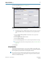
The latency calculator gives you an approximate indication of the latency of your
Viterbi decoder. Latency is the number of clock cycles it takes for the data to be
processed and output. It is measured from the first symbol to enter the MegaCore
function (sink_sop) up to the first symbol to leave the MegaCore function
(source_sop). The latency depends on the parameters.
1
For the precise latency, perform simulation.
The latency calculator uses the following formula for the hybrid architecture:
Number of clock cycles = Z × V
where:
V is the traceback length value that is in the input tb_length
Z = 10, if log2C = 3
Z = 2log2C, if log2C > 3
log2C = lmax – 2 – log2A, where Ais ACS units
1
For the parallel architecture the number of clock cycles is approximately 4V
Test Data Tab
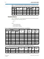
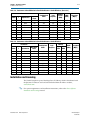
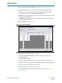
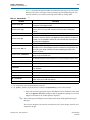
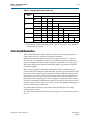
Table 3–6 shows the options that can be set in the Test Data tab.
Table 3–6. Test Data
Parameter
Description
The number of bits per block.
Number of bits per block
Signal to noise ratio (dB)
The number of bits per block × the number of blocks must be less than
50,000,000.
The signal to noise ratio, which must be between 1 and 100.
The number of blocks.
Number of blocks
The number of bits per block × the number of blocks must be less than
50,000,000.
Pattern A
Enter the puncturing pattern A.
Pattern B
Enter the puncturing pattern B.
Signals
The Viterbi decoder uses the Avalon Streaming (Avalon-ST) interface for its data input
and output. The input is an Avalon-ST sink and the output is an Avalon-ST source.
The Avalon-ST interface READY_LATENCY parameter is set to 1.
f For more information about the Avalon-ST interface, refer to the Avalon Interface
Specifications.
Viterbi Compiler
User Guide
November 2012 Altera Corporation