1
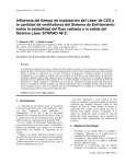
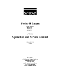
PCI-bus Fiber Link Controller Card
installation for FH Series/Fenix Heads
These instructions cover installation of SYNRAD’s PCI-bus Fiber Link Controller Card (FLCC) in IBMcompatible computers when installing WinMark Pro version 4.0.0.×××× software on computers running
Windows® 98, NT4, 2000, or XP operating systems. Installation will vary slightly depending on the operating
system being used.
Note:
Version 4.0.0.3773 and above supports only PCI-bus FLCCs running on Windows 98, NT4, 2000, and
XP operating systems.
Version 3.1.0.3767 and above supports only PCI-bus FLCCs running on Windows NT4 systems.
WinMark Pro version 2.1.0.3767 and above supports either ISA- or PCI-bus FLCCs running on
Windows 95/98 systems.
The FLCC is very sensitive to static electricity discharges. Because it is possible to damage the FLCC or your
computer through improper handling, please follow the installation directions carefully.
Caution
possible equipment damage
Static sensitive components on the Fiber Link Controller Card may be damaged if exposed to static electricity
discharges. Always wear a static control wrist strap when handling the Fiber Link Controller Card. If a static
control wrist strap is not available, ground yourself by maintaining continuous contact with your computer’s
grounded metal chassis.
Configure the FLCC
+
We recommend that you configure DIP switches before installation. Figure 1 shows default DIP switch settings.
Figure 1 DIP switch settings
1
Table 1 lists FLCC DIP switch functions.
Table 1 DIP switch functions
DIP SW#
Default Position
Switch Function
6
OFF
Set to “ON” only when controlling a DH Series Marking Head.
5
OFF
Fast Acting Safety Interlock (FASI) – ON enables the FASI function; OFF
disables the Interlock function. When the FASI Interlock is enabled, a high
level input must be present on Input # 3 (IN3) to enable lasing.
4
ON
Card ID# LSB
3
ON
2
ON
1
ON
Card ID# MSB
Because the Windows operating system and not the user assigns the card address, the Card ID Number is not
important. The card address, set by the Card ID# DIP switches, supports future improvements to WinMark Pro.
When SW3–SW6 are set to ON, the Card ID# = 0; when SW3–SW6 are set to OFF the Card ID# = 15. For
example, if SW3, SW4, and SW5 = OFF and SW6 = ON, then the Card ID# = 7.
Install WinMark Pro version 4.0.0.××××
software
To install WinMark Pro v4.0.0.×××× software, perform the following steps:
1
Double-click the WinMark_Setup.EXE icon.
2
Follow the instructions shown in the installation dialog boxes.
3
When installation is complete, the WinMark Pro installer will recommend restarting your computer.
If you have not installed the FLCC, click Cancel and then shut down your computer normally.
Install the FLCC
To install the PCI-bus FLCC, perform the following steps:
1
Turn off your computer, but leave it plugged into a properly grounded outlet. Leaving the computer
plugged in means that the computer chassis will remain grounded, enabling you to discharge harmful
static electricity before handling sensitive electronic components.
2
Remove the computer’s case or cover to expose the expansion slots. Locate an empty PCI bus slot (the
PCI-bus FLCC will not physically fit in an ISA slot).
3
If there is a “space filler” metal bracket covering the PCI slot, then remove the bracket. Save the
screw.
2
4
Make sure you are grounded before handling the FLCC. While grounded, install the FLCC in the PCI
slot. The gold contact fingers on the card should slide into the mating PCI bus slot without using
excessive force.
5
When the card is properly seated, use the screw removed in step 3 to secure the card to the computer
chassis.
6
Reinstall the computer’s case or cover.
Connect the Fiber Optic cable
To install the Fiber Optic cable, refer to Figure 2 and perform the following steps:
Fiber Optic Transmitter Port
Fiber Optic Receiver Port
Cable Latch Slot
Figure 2 Fiber Link Controller Card connectors
1
With the back of the computer accessible, locate the Fiber Optic Receiver/Transmitter port on the Fiber
Link Controller Card.
2
Remove the rubber dust caps from the fiber optic ports.
3
Locate the Fiber Optic cable in the shipping box. The end that attaches to the FLCC terminates into a
single duplex connector.
4
Insert the duplex connector into the Fiber Optic Receiver/Transmitter port on the FLCC. When
properly connected, the latch on the connector should clip into the cable latch slot. You should not
be able to remove the Fiber Optic cable without depressing the latch.
Note:
The fiber optic connection is the only connection necessary to control Fenix or FH Series Marking
Heads; no other connections are required. When connecting to a DH Head, see the DH Series
Marking Heads section below.
5
Connect the other end of the Fiber Optic cable to your Marking Head.
Restart your computer
1
Re-boot your computer.
2
On Windows NT4, 2000, and XP systems, the Found New Hardware wizard will detect the newly
installed PCI card and the Synmkh.sys device driver installed by WinMark Pro version 4.
3
2a
Follow Found New Hardware wizard instructions to associate the Fenix/FH Laser Marking Devices
hardware (FLCC) with its device driver.
3
On Windows 98 systems, the New Hardware Found wizard will detect the Fenix/FH Laser Marking
Devices hardware (FLCC).
3a
Wait while the New Hardware Found wizard updates the Driver Information Database.
4
Allow your computer to complete the start-up process.
Verify the FLCC’s functionality
Follow the steps below to verify that the PCI card is functioning properly.
1
Double-click the Shortcut to WinMark Pro icon on your desktop.
2
When WinMark Pro opens, select the appropriate lens and click OK.
3
From the Tools menu, click General Settings…. On the Application Settings tab, locate the I/O Card
Selection property and verify that the PCI card is properly identified.
4
Create a new drawing, or open an existing file, and mark the drawing.
This completes the installation of your PCI-bus Fiber Link Controller Card.
DH Series Marking Heads
When using the PCI card to control a DH Series Marking Head, connect the BNC cable from the laser’s
CTRL connector to the BNC connector shown in Figure 3. Set switch SW6 on the FLCC (Figure 1) to “ON”.
The Fiber Optic cable only transmits position data to the Head; the CTRL cable between the Head and the
FLCC sends PWM (power) commands to the laser.
Figure 3 FLCC connection for DH Series Marking Heads
4