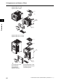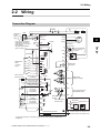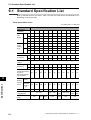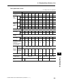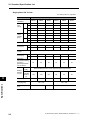
1
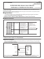
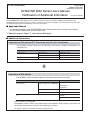
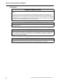
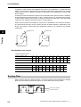
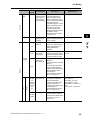
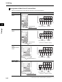
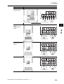
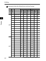
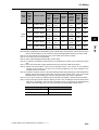
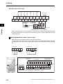
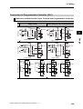
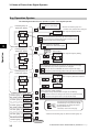
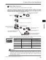
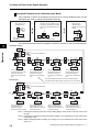
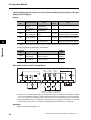
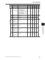
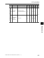
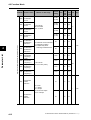
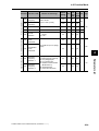
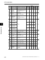
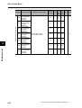
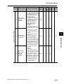
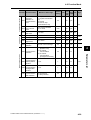
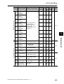
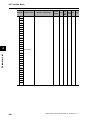
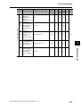
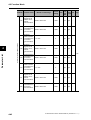
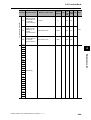
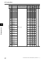
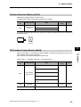
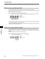
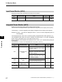
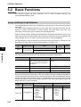
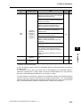
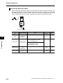
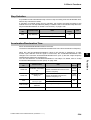
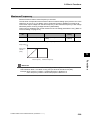
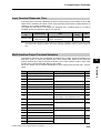
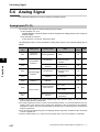
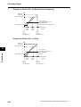
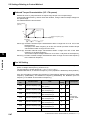
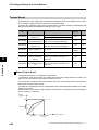
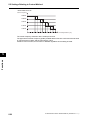
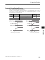
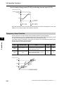
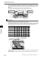
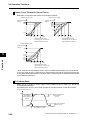
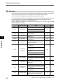
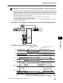
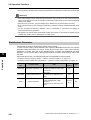
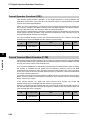
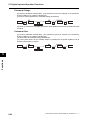
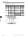
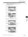
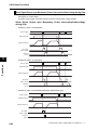
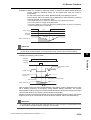
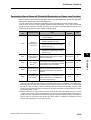
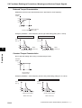
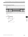
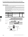
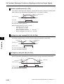
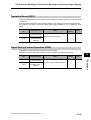
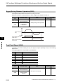
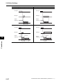
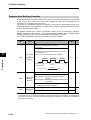
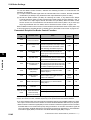
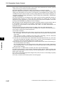
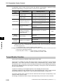
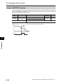
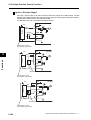
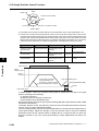
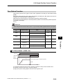
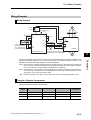
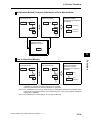
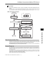
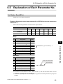
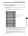
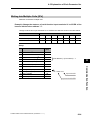
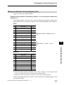
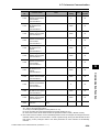
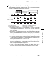
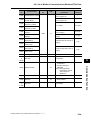
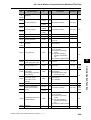
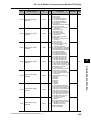
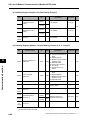
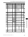
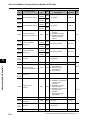
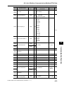
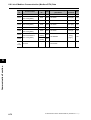
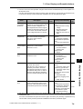
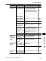
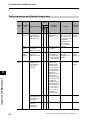
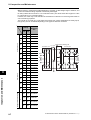
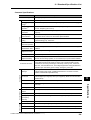
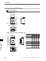
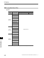
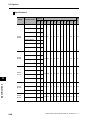
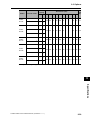
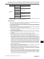
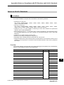
5-2 Basic Functions
A relation diagram for frequency reference selection is as follows:
Multi-step speed input
CF1-4,SF1-7
ON
Multi-step Speed
Reference A021-A035
Set
frequency
[FV]+[FI]
OFF
+
[FV/FI] terminal
Analog voltage
input[FV]
OFF
Analog current
input[FI]
ON
[FV/FI] selection
A005
00
02
03
[FV/FI] terminal
allocation
None
Yes
OFF
External Digital
Operator
[volume]
ON
OFF
Forced Operator
ON
ON
Digital Operator
A020/A220=F001
5
Functions
*1
OFF
Frequency Reference
Selection A001/A201
01
Modbus
communication
02
00
Optional board
Forced terminal block
ON
03
04
Pulse train input
[RP]
06
OFF
07
10
(Others)
Operation
Frequency
Selection 1
A141
Operation
Frequency
Selection 2
A142
Operation
Function
Operator
Selection
A143
(+)
(-)
(×)
Frequency operation function
*1. If the frequency reference source is a Digital Operator, the frequency can be set using F001. If the
frequency reference source is not a Digital Operator, F001 shows a monitored value of the specified
frequency. If Frequency Change is enabled (b163 = 01) during monitoring, the frequency can be
changed by pressing the Up/Down keys on the d001 or d007 monitor display.
5-21
SYSDRIVE MX2 Series USER'S MANUAL (3G3MX2-A@@@@)