1
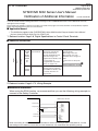
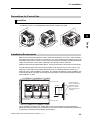
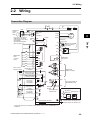
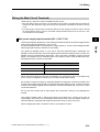
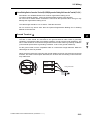
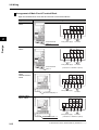
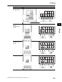
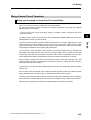
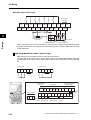
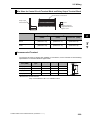
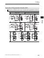
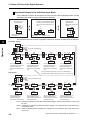
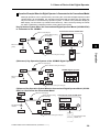
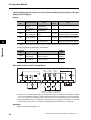
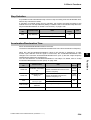
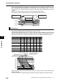
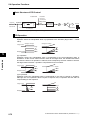
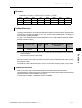
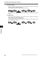
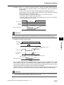
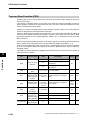
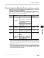
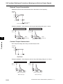
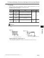
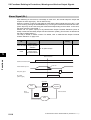
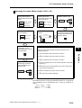
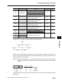
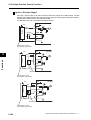
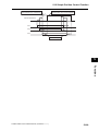
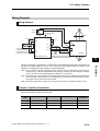
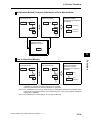
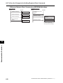
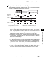
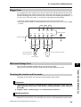
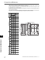
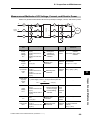
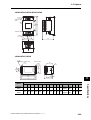
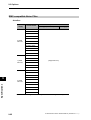
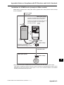
2-2 Wiring
Wiring Example (Sink Logic)
Shorting bar
(sink logic)
RS−
RS+
S7/EB
MP
2
S6
S5/TH S4/GS2 S3/GS1
RP
FS
FV
FI
Design
Variable Resistor
Frequency reference
(1 to 2 kΩ)
S2
SC
S1
AM
SC
PC
PSC
P24
P2
P1/EDM
RY
RY
Signal during Frequency arrival
signal
RUN
Frequency reading
(27 VDC 50 mA max.)
When connecting a relay to the multi-function output terminal, install a surge-absorbing diode
in parallel with the relay. The output circuit can break down due to surge voltage when the relay
is switched on/off.
Switching Method for Input Control Logics
Multi-function input terminals are set to sink logic at the factory.
To switch the input control logic to source logic, remove the shorting bar between terminals
P24 and PSC on the control circuit terminal block, and connect it between terminals PSC and
SC.
(2) Source logic
(1) Sink logic
S2
S1
SC PSC P24
S2
S1
Shorting bar
SC PSC P24
Shorting bar
Communication
RS-485
Logic common and
power supply
Logic input
RS− S7
/EB
S6
S5 S4
S3 S2
/TH /GS2 /GS1
S1
SC PSC P24
Relay output
RS+ MP
RP
FS
FV
FI
SC
AM
PC
P1
P2
/EDM
Shorting
bar
MB MA MC
Communication Pulse Pulse Analog input and
output input
power supply
RS-485
2-19
Analog
output
Logic output
SYSDRIVE MX2 Series USER'S MANUAL (3G3MX2-A@@@@)