1
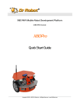
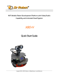
25 Valleywood Drive, Unit 20
Markham, Ontario, L3R 5L9, Canada
Tel: (905) 943-9572 Fax: (905) 943-9197
i90
Robot User Quick Guide
Copyright © 2006, Dr Robot Inc. All Rights Reserved. www.DrRobot.com
-1-
Copyright Statement
This manual or any portion of it may not be copied or duplicated without the expressed written consent of Dr
Robot.
All the software, firmware, hardware and product design accompanying with Dr Robot’s product are solely owned
and copyrighted by Dr Robot. End users are authorized to use for personal research and educational use only.
Duplication, distribution, reverse-engineering, or commercial application of the Dr Robot or licensed software and
hardware without the expressed written consent of Dr Robot is explicitly forbidden.
Copyright © 2006, Dr Robot Inc. All Rights Reserved. www.DrRobot.com
-2-
Table of Contents
I.
Key Features
4
II.
i90 Base Robot and Upgrade Options
5
i90 Robot Standard Components
5
2
Upgrade Package I (Sputnik )
5
Upgrade Package II (Sentinel2)
5
2
III.
Upgrade Package III (Scout )
6
Upgrade Package IV (Stealth)
6
Individual Upgrade Options
6
Knowing Your Robot
7
External Components
7
Numbering of Modules and Servos
8
Operation Scenario
9
Network Connection
10
Internet Remote Monitoring/Tele-operation
11
Advanced Network Settings
11
Recharging
12
To charge the i90 robot with standard charger unit
12
To charge the i90 robot with the Auto-Docking Auto-recharging station (optional)12
IV.
V.
Software Installation
13
Install the Joystick Controller
13
Auto-Docking and Auto Recharging Station
14
Setting up the Auto-docking and Auto-recharging Station for i90 (with appropriate upgrade) 14
Autonomous Recharging
15
Manual Command of Self-Docking Recharging
15
Manual Forced Recharging
15
VI.
Robot Operations
16
VII.
Programming
16
Copyright © 2006, Dr Robot Inc. All Rights Reserved. www.DrRobot.com
-3-
Congratulation on your investment and welcome to the i90 robot family.
I. Key Features
Pan Tilt Zoom (10X) High Resolution CCD Camera Max 704x480 pixels, max 30fps, 10X optical
zoom and 10x digital zoom
Two-Way Audio
Fully Wireless Networked (WiFi 802.11G)
Lightweight and Large Payload Capacity i90 base robot weights 6Kg, Max payload 15Kg (optional
40Kg)
320x240 Color Programmable Touch LCD
Extended Operating Time 3 hours (i90 base robot with standard battery pack) and upgradeable to 6, 12
or 24 hours in between recharge
Tele-Operation and Remote Monitoring via Internet the included i90 Robot ExplorerTM program
features remote monitoring, robot control and two-way audio
Constellation Autonomous Navigation Positioning System (optional) continuously provides up to 1
inch (2 cm) position accuracy and 2 degree orientation accuracy
Auto-Docking and Auto-Recharge Station (optional) used with Constellation system, providing robot
24x7 fully autonomous operation and self recharging capability without human assistance
Large Selection of Upgrades 5 DOF servo arms with gripper, Camera on arm, Stereo Camera Head, 3D
laser scanner (range finder), multiple Cameras, long range RFID reader and more
OS Independent Programming Support Operating system independent robot control and data
communication protocols are provided for developing customized robot program for any operating system or
devices that supporting TCP/IP communication. High level ActiveX controls are also provided for fast
development under Windows 2000 or XP
Copyright © 2006, Dr Robot Inc. All Rights Reserved. www.DrRobot.com
-4-
II. i90 Base Robot and Upgrade Options
i90 Robot Standard Components
i90 mechanical chassis
Pan-tilt-zoom (704X480) CCD camera with two-way audio
2W Speaker with amplifier
Color LCD (320x240) PDA
Robot sensing and motion controller
12V DC motor with 800 count optical encoder
DC motor driver module
Ultrasonic range sensor module
Sharp IR distance measuring sensor
Pyroelectric human motion sensor module
IO Interface board
WiFi 802.11G wireless module
RS232 cross-over serial cable
RS232 interface module
Power and charge controller
DC-DC power module
Universal power supply
12V Ni-MH 3800mAh battery pack
Joystick
i90 robot explorer program
Software SDK and API
I90-ME
AV-PTZ-VH
SP-AM-2W
PDM1950
PMS5005
MCA-50
MDM5253
DUR5200
GP2Y0A21YK
DHM5150
EXPIO
WFS802G
CCR2150
MCR3210
PMCHR12
PDCDC-3
UPS14
BPN1238
LOGIJO
x1
x1
x1
x1
x1
x2
x1
x3
x7
x2
x1
x1
x1
x1
x1
x1
x1
x2
x1
x1
x1
Upgrade Package I (Sputnik2)
Sputnik 2
i90 robot
Stereo camera animated head
i90
SCAM-HEAD
1
1
i90
CONST-NAV
CONST-TRANSTD
AUTO-CHAR12
1
1
Upgrade Package II (Sentinel2)
Sentinel 2
i90 robot
Constellation navigation/position system
Constellation navigation/position transponder
Auto-docking auto-recharging station
Copyright © 2006, Dr Robot Inc. All Rights Reserved. www.DrRobot.com
-5-
3
1
Upgrade Package III (Scout 2)
Scout 2
i90 robot
5 DOF servo arm with gripper
Mini 640x480 wireless camera
i90
SARM-5DOF
AXCAM
1
2
1
Sentinel 2
SCAM-HEAD
SARM-5DOF
AXCAM
1
1
2
1
Upgrade Package IV (Stealth)
Stealth
Sentinel 2 robot
Stereo camera animated head
5 DOF servo arm with gripper
Mini 640x480 wireless camera
Individual Upgrade Options
5 DOF servo arm with gripper
Stereo camera animated head
3D Laser Scanner
Mini 640x480 CCD wireless camera
Pan-tilt-zoom (704X480) camera with two-way audio
Constellation navigation/position system
Long range RFID system (reader and tags)
Constellation navigation/position transponder
Auto-docking auto-recharging station
2 X 9000mAH 12V Ni-MH battery
SARM-5DOF
SCAM-HEAD
3DLAS4M
AXCAM
AV-PTZ-VH
CONST-NAV
RFID-LR-U
CONST-TRAN-SD
AUTO-CHAR12
BPN1290
Please contact [email protected] for custom design and integration inquiry.
Copyright © 2006, Dr Robot Inc. All Rights Reserved. www.DrRobot.com
-6-
III. Knowing Your Robot
External Components
The following figures illustrate the key functional components you should be able to identify on the i90 robot with
Sentinel upgrade package, Stereo Camera Animated Head and 3D Laser scanner.
3D Laser Range
Scanner
Stereo Camera Animated
Head System **
LED (Main Power)
Constellation Receiver **
Pan-Tilt-Zoom
Camera
Human Sensor
Color LCD PDA
Sonar Range Sensor
IR Range Sensor
Protection Bumper
** With optional upgrades
LED (Charging
Power Signal)
Power Switch
Secondary Recharging
Socket
Auto-Docking & AutoRecharging Socket **
** With optional upgrades
Copyright © 2006, Dr Robot Inc. All Rights Reserved. www.DrRobot.com
-7-
Numbering of Modules and Servos
Electrical Module
Location / Setting
Ultrasonic #1
A - Left front
Ultrasonic #2
B - Middle front
Ultrasonic #3
C - Right front
Human Sensor #1
D - Left front, upper lever
Human Sensor #2
E - Right front, upper lever
Infrared Range Sensor #1
F – Front left
Infrared Range Sensor #2
G – Front left
Infrared Range Sensor #3
H – Front middle
Infrared Range Sensor #4
I – Front middle
Infrared Range Sensor #5
J – Front middle
Infrared Range Sensor #6
K – Front right
Infrared Range Sensor #7
L – Front right
Constellation Receiver #1
M - Left Constellation Receiver
Constellation Receiver #1
N - Right Constellation Receiver
DC Motor #1 with quadrature encoder
O - Left , use channel 1
DC Motor #2 with quadrature encoder
P - Right, use channel 2
Sensor Modules Locations (Top View)
Copyright © 2006, Dr Robot Inc. All Rights Reserved. www.DrRobot.com
-8-
Operation Scenario
As shown in the typical operation diagram below, the Home PC running the i90 Robot Explorer program (also
called server PC) can be mounted on the robot or off the robot. The Home PC should connect to the wireless
router via either:
•
Network cable – Connect your PC to one of the LAN ports on the back of the router (DO NOT connect to
the WAN port), or
•
Wireless – To connect your PC to the wireless router, configure your PC’s wireless settings using the
default configuration settings shown on the first page of this manual.
Server Program
Client Program
Copyright © 2006, Dr Robot Inc. All Rights Reserved. www.DrRobot.com
-9-
Network Connection
There are over three 802.11G wireless devices in the robot and they are configured with the following wireless
network settings:
SSID
WEP
KEY
dri
128bits
XXXXXXXXXXXXXXXXXXXXXXXXX
Gateway
Subnet Mask
Key Type
Wireless Devices
Robot IP (WiFi Module 1)
Robot Secondary IP (WiFi Module 2) (option)
Main PTZ Camera
Color LCD PDA
Stereo Camera Animated Head (Left) (Option)
Stereo Camera Animated Head (Right) (Option)
192.168.0.200
255.255.255.0
Open Key
IP
192.168.0.208
192.168.0.205
192.168.0.199
192.168.0.202
192.168.0.91
192.168.0.90
In this manual, the Server/Home PC network parameters are as following
Home PC / Server
192.168.0.104
192.168.0.200
The pre-configured wireless 802.11G router has the following settings:
SSID
WEP
KEY
Key Type
dri
128bits
XXXXXXXXXXXXXXXXXXXXXXXXX
Open Key
Router LAN
Login ID
Password
192.168.0.200
XXXXXX
XXXXXX
With virtual server settings as following
Virtual Server
i90 Robot Explorer program
i90 Robot Explorer program
i90 Robot Explorer program
Main PTZ Camera
Main PTZ Camera
Main PTZ Camera
Stereo Camera Animated Head (Left)
Stereo Camera Animated Head (Left)
Stereo Camera Animated Head (Left)
Stereo Camera Animated Head (Right)
Stereo Camera Animated Head (Right)
Stereo Camera Animated Head (Right)
Wireless Router
i90 Robot Explorer Program Login
Main PTZ Camera
Stereo Camera Animated Head (Left) (Option)
Stereo Camera Animated Head (Right) (Option)
Port
7050
7060
7070
8081
5002
5003
8082
7002
554
8083
7003
555
Protocol
TCP/IP
TCP/IP
TCP/IP
TCP/IP
UDP
UDP
TCP/IP
TCP/IP
TCP/IP
TCP/IP
TCP/IP
TCP/IP
Login
XXXXXXX
XXXXXXX
XXXXXXX
XXXXXXX
XXXXXXX
Copyright © 2006, Dr Robot Inc. All Rights Reserved. www.DrRobot.com
- 10 -
Server IP
192.168.0.104
192.168.0.104
192.168.0.104
192.168.0.199
192.168.0.199
192.168.0.199
192.168.0.91
192.168.0.91
192.168.0.91
192.168.0.90
192.168.0.90
192.168.0.90
Password
XXXXXXX
XXXXXXX
XXXXXXX
XXXXXXX
XXXXXXX
Internet Remote Monitoring/Tele-operation
If Internet remote monitoring/control is required, you need to connect the wireless router WAN port to your
current broadband Internet modem (this is optional and is not required for running the robot).
If firewall is in-place in your network, you also need to make sure all the networks port used by the wireless
st
devices (e.g. 8081, 5002, 5003 for the main PTZ camera, 8082, 7002, 554 for the 1 mini Camera, 8083,
nd
7003 and 555 for the 2 mini Camera) and 7050, 7060, 7070 on the server and remote client sides are not
blocked for the Internet remote monitoring/control tasks to operate properly.
Advanced Network Settings
It’s possible to use different network settings (e.g. IP) for the server PC, but the “Virtual Server” settings on the
router must also be changed accordingly in order for the Internet remote monitoring feature to work properly.
You could also change the router settings such as IP and SSID etc,. If you need to do so, you are required to
change the Network settings on the WiFi module on the robot by following the guidelines as illustrated on the
WiFi Module manual.
Copyright © 2006, Dr Robot Inc. All Rights Reserved. www.DrRobot.com
- 11 -
Recharging
Note: The robot must be turned on to be charged.
To charge the i90 robot with standard charger unit
1.
Turn on the robot
2. Plug in and power up the charging unit, and plug the charger cable into the
secondary charger socket at the back of the i90 robot.
To charge the i90 robot with the Auto-Docking Auto-recharging station (optional)
Please see the Auto-docking and Auto Recharging Station session for detail
Copyright © 2006, Dr Robot Inc. All Rights Reserved. www.DrRobot.com
- 12 -
IV. Software Installation
Using the i90 Program CD to install:
• i90 Robot Explorer program on the Home/server PC
• i90 Robot Explorer Client program on the remote client PC (if Internet remote operation and monitoring is to be
used)
• Dr Robot Map Creator program on the Home/server PC
• Pan-Tilt-Zoom Camera Development Kit (P/N: AV-PTZ-VH)
• 5DOF Servo Arm with Gripper control program on the Home/server PC (if the optional 5DOF Servo Arm is
installed, P/N: SARM-5DOF)
• 3D Laser Scanner Range Finder program on the Home/server PC (if the optional 3D Laser Scanner installed,
P/N: 3DLAS4M)
• Stereo Camera Animated Head Controller program and the Mini Wireless Camera (P/N: AXCAM) Development
Kit on the Home/server PC (if the optional Stereo Camera Animated Head is installed, P/N: SCAM-HEAD)
• RFID Management program on the Home/server PC (if the optional Long Range RFID System is installed, P/N:
RFID-LR-U)
Install the Joystick Controller
Please follow the installation instructions provided with the joystick controller and install the driver for the device
on both the Server and Client PC (if applicable). XP and 2000 normally will recognize the device automatically
with plug and play feature.
To verify the joystick installation, run Control Panel > Printers and Other Hardware > Game Controllers. Selecting
this option will open a dialog box listing installed hardware typically used for gaming. The installed joystick will
appear if it has been properly installed.
Copyright © 2006, Dr Robot Inc. All Rights Reserved. www.DrRobot.com
- 13 -
V. Auto-Docking and Auto Recharging Station
Setting up the Auto-docking and Auto-recharging Station for i90 (with appropriate upgrade)
Refer to the figure below; the charging station comes in two parts: Constellation Transponder Tube for charger
with top mounting panel, the main charging unit with lower mounting panel.
Forced Charging Switch
Constellation Transponder for Charger
with Top Mounting Panel
Charger Docking Adjustment Screw
Main Charging Unit
Lower Mounting Panel
Charger Contact Plug
Auto-docking and Auto-recharging Station
Setting up the charging station:
1.
Choose an easy access spot on the wall for mounting the charging station. Maker sure the floor is level at
the spot for easy setup.
2. Mounting the top panel (pre-assembled with the Constellation Transponder Tube for Charger) with
height of 71.5 cm measured from the top edge of the top mounting panel (see figure below) to floor. Use
leveler to have it as level as possible.
Copyright © 2006, Dr Robot Inc. All Rights Reserved. www.DrRobot.com
- 14 -
Charger Constellation Transponder
Tube Position Mark
71.5
cm
3. Remove the lower mounting panel from the main charging unit.
4. Mounting the lower panel to the wall under the top mounting panel.
5. Assembling back the main charging unit to the lower panel, don’t tighten the “Charger Docking
Adjustment Screws”(shown in figure “Auto-docking and Autorecharging Station” above) yet.
6. Dock the robot (Charging Socket) into the Charger Contact Plug (as
shown on the right figure).
7. Tighten adjustment screws; manually push robot out and back it in the
charger again. If the docking action is smooth, adjustment is done,
otherwise finely adjusting the position of the main charger unit by
loosing the adjustment screws and repeat steps above.
8. Plug the small power connector into the Constellation Transponder
tube.
9. Plug the main power cord to the wall power unit.
Autonomous Recharging
When the robot is running at auto Patrol mode, when the batteries are running low, robot will automatically return
to the charger and charge.
Manual Command of Self-Docking Recharging
Using the “Docking” or “Charge” function button found on the i90 Robot Explorer Server or Client software to
dock the robot into the charging station and recharge.
Manual Forced Recharging
When manual recharge is required, first manually dock the
robot into the charging station, with robot run on, toggle on
the “Forced Charging Switch” found on the lower right side of
the charging unit as shown below. The charging LED light on
the back of the robot will light up. When charging is
completed, the re-charging will stop automatically. You need
to manually switch off the “Forced Charging Switch” after
use.
Forced Charging Switch
Copyright © 2006, Dr Robot Inc. All Rights Reserved. www.DrRobot.com
- 15 -
VI. Robot Operations
Please refer “i90 Robot Explorer Program” Manual for reference.
VII. Programming
Please refer to the following documents for high level programming using ActiveX control on Windows
environment.
Robot Sensing and Control: “WiRobot SDK API Reference Manual” and “WiRobot SDK API (Supplementary for
Sentinel) Reference Manual”
Pan-Tilt-Zoom Camera: “PTZ Camera ActiveX Control Reference Manual”
Please refer to the following documents for low level programming using raw protocol:
Robot Sensing and Control: “PMS5005 Protocol Reference Manual with Support for Constellation System and
Power Controller”
Please refer to the following documents for high level programming with “i90 Robot Explorer server program”:
“i90 Robot Explorer Sever-Client Protocol”
Copyright © 2006, Dr Robot Inc. All Rights Reserved. www.DrRobot.com
- 16 -