1
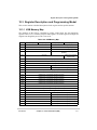
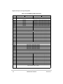
Register Descriptions
7
3
Field
2
—
Reset
1
RTSL
0
IEC
0000_0000
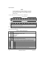
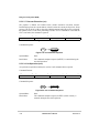
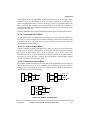
R/W
Write only
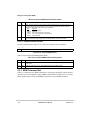
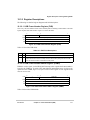
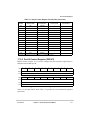
Address
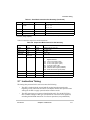
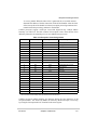
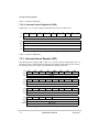
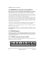
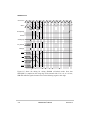
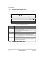
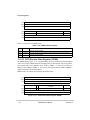
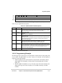
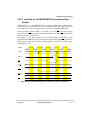
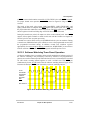
MBAR + 0x110 (UACR0), 0x150 (UACR1)
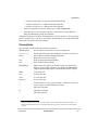
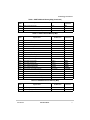
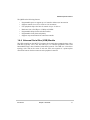
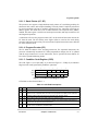
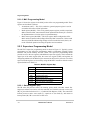
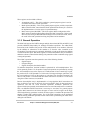
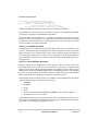
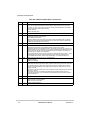
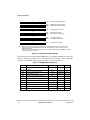
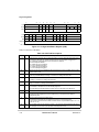
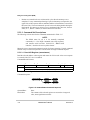
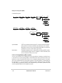
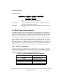
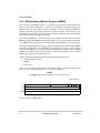
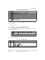
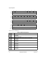
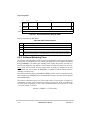
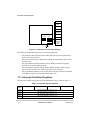
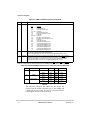
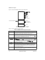
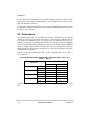
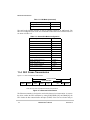
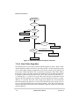
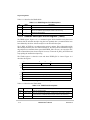
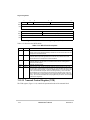
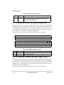
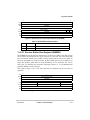
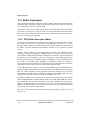
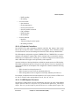
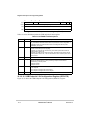
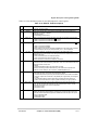
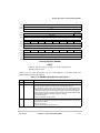
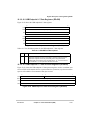
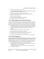
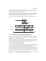
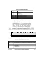
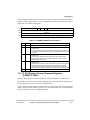
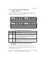
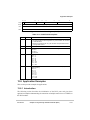
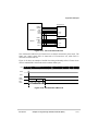
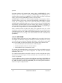
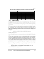
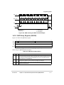
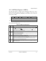
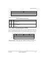
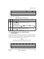
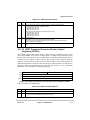
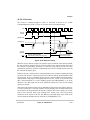
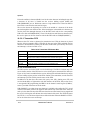
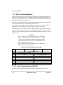
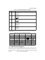
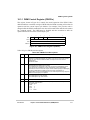
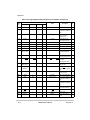
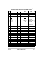
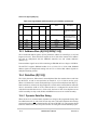
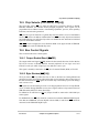
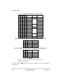
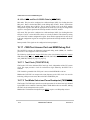
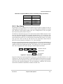
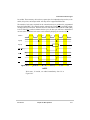
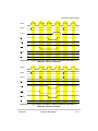
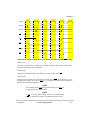
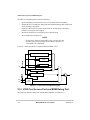
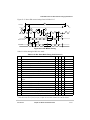
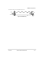
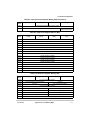
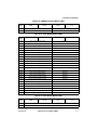
Figure 16-10. UART Auxiliary Control Registers (UACRn)
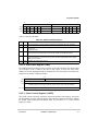
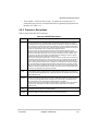
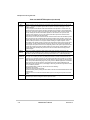
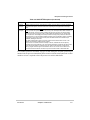
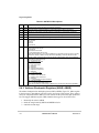
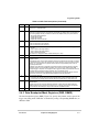
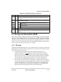
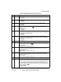
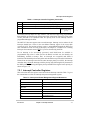
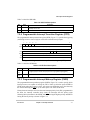
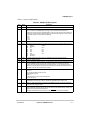
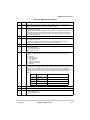
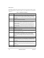
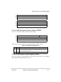
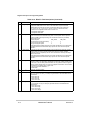
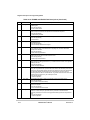
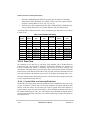
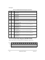
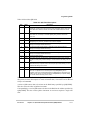
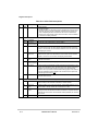
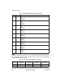
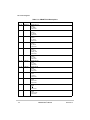
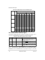
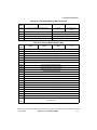
Table 16-8 describes UACRn fields.
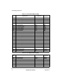
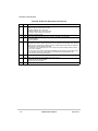
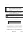
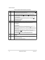
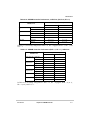
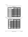
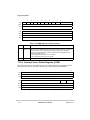
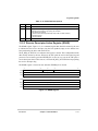
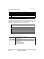
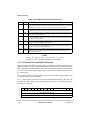
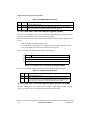
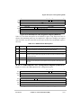
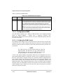
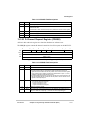
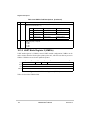
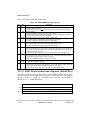
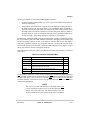
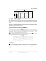
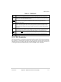
Table 16-8. UACRn Field Descriptions
Bits
Name
7–3
—
2–1
RTSL
0
IEC
Description
Reserved, should be cleared.
RTS level. Determines when RTS is negated by the receiver relative to the fullness of the receiver
FIFO. Note that RTS must first be manually asserted by a write to UOP0n.
00 FIFO level control disabled
01 Receiver FIFO ≥ 25% full
10 Receiver FIFO ≥ 50% full
11 Receiver FIFO ≥ 75% full
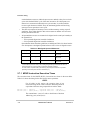
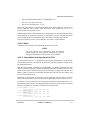
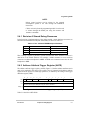
Receiver overrun can be prevented by using the RTS output to control the CTS input of the
transmitting device. Attempting to program a receiver and transmitter in the same channel for RTS
control is not permitted and disables RTS control for both.
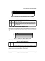
Input enable control.
0 Setting the corresponding UIPCRn bit has no effect on UISRn[COS].
1 UISRn[COS] is set and an interrupt is generated when the UIPCRn[COS] is set by an external
transition on the CTS input (if UIMRn[COS] = 1).
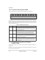
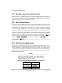
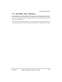
16.3.10 UART Interrupt Status/Mask Registers
(UISRn/UIMRn)
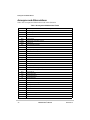
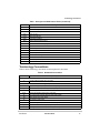
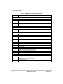
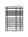
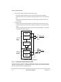
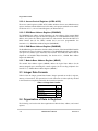
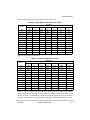
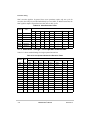
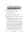
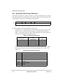
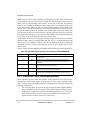
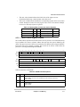
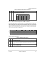
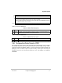
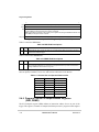
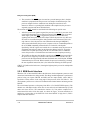
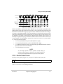
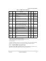
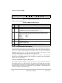
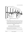
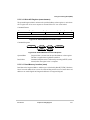
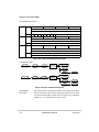
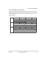
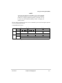
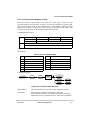
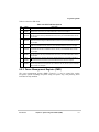
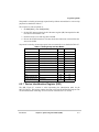
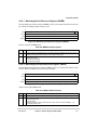
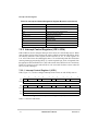
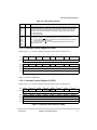
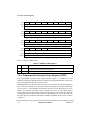
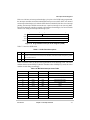
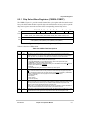
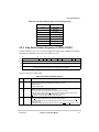
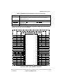
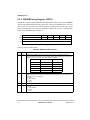
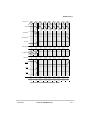
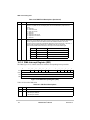
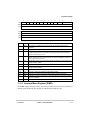
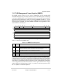
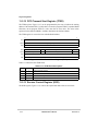
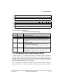
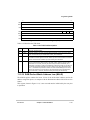
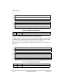
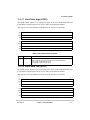
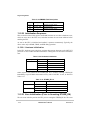
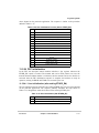
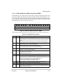
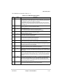
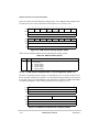
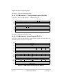
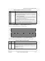
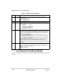
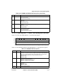
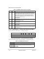
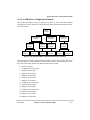
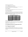
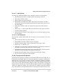
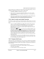
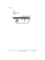
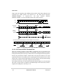
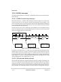
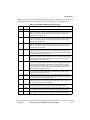
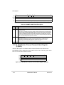
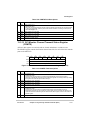
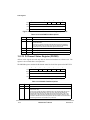
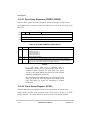
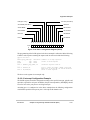
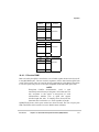
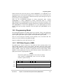
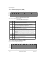
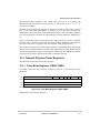
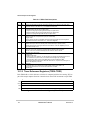
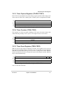
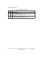
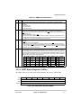
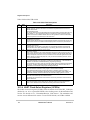
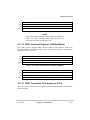
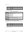
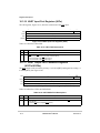
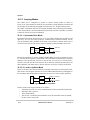
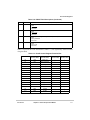
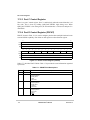
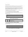
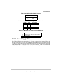
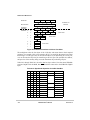
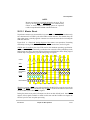
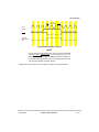
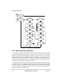
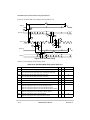
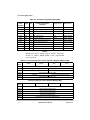
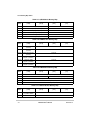
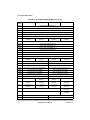
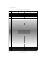
The UART interrupt status registers (UISRn), Figure 16-11, provide status for all potential
interrupt sources. UISRn contents are masked by UIMRn. If corresponding UISRn and
UIMRn bits are set, the internal interrupt output is asserted. If a UIMRn bit is cleared, the
state of the corresponding UISRn bit has no effect on the output.
NOTE:
True status is provided in the UISRn regardless of UIMRn
settings. UISRn is cleared when the UART module is reset.
Field
7
6
COS
ABC
Reset
RXFIFO
TXFIFO
3
2
1
0
RXFTO
DB
FFULL/RxRDY
TxRDY
0000_0000
R/W
Read only for status, write only for mask.
Address
MBAR + 0x114 (UISR0), 0x154 (UISR1); MBAR + 0x114 (UIMR0), 0x154 (UIMR1)
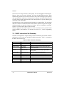
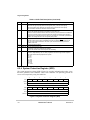
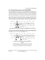
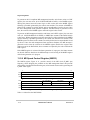
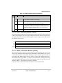
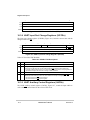
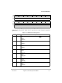
Figure 16-11. UART Interrupt Status/Mask Registers (UISRn/UIMRn)
MOTOROLA
Chapter 16. UART Modules
16-13