1
Real-Time Debug Support
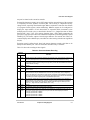
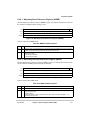
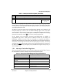
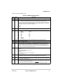
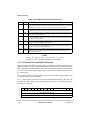
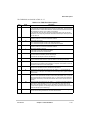
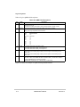
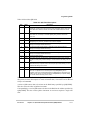
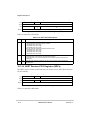
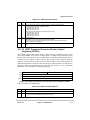
The breakpoint status is also posted in CSR. Note that CSR[BSTAT] is cleared by a CSR
read when either a level-2 breakpoint is triggered or a level-1 breakpoint is triggered and a
level-2 breakpoint is not enabled. Status is also cleared by writing to TDR.
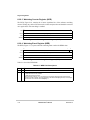
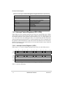
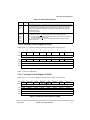
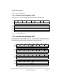
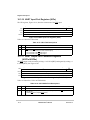
BDM instructions use the appropriate registers to load and configure breakpoints. As the
system operates, a breakpoint trigger generates the response defined in TDR.
PC breakpoints are treated in a precise manner—exception recognition and processing are
initiated before the excepting instruction is executed. All other breakpoint events are
recognized on the processor’s local bus, but are made pending to the processor and sampled
like other interrupt conditions. As a result, these interrupts are imprecise.
In systems that tolerate the processor being halted, a BDM-entry can be used. With
TDR[TRC] = 01, a breakpoint trigger causes the core to halt (PST = 0xF).
If the processor core cannot be halted, the debug interrupt can be used. With this
configuration, TDR[TRC] = 10, the breakpoint trigger becomes a debug interrupt to the
processor, which is treated higher than the nonmaskable level-7 interrupt request. As with
all interrupts, it is made pending until the processor reaches a sample point, which occurs
once per instruction. Again, the hardware forces the PC breakpoint to occur before the
targeted instruction executes. This is possible because the PC breakpoint is enabled when
interrupt sampling occurs. For address and data breakpoints, reporting is considered
imprecise because several instructions may execute after the triggering address or data is
detected.
As soon as the debug interrupt is recognized, the processor aborts execution and initiates
exception processing. This event is signaled externally by the assertion of a unique PST
value (PST = 0xD) for multiple cycles. The core enters emulator mode when exception
processing begins. After the standard 8-byte exception stack is created, the processor
fetches a unique exception vector, 12, from the vector table.
Execution continues at the instruction address in the vector corresponding to the breakpoint
triggered. All interrupts are ignored while the processor is in emulator mode. The debug
interrupt handler can use supervisor instructions to save the necessary context such as the
state of all program-visible registers into a reserved memory area.
When debug interrupt operations complete, the RTE instruction executes and the processor
exits emulator mode. After the debug interrupt handler completes execution, the external
development system can use BDM commands to read the reserved memory locations.
If a hardware breakpoint such as a PC trigger is left unmodified by the debug interrupt
service routine, another debug interrupt is generated after the completion of the RTE
instruction.
MOTOROLA
Chapter 5. Debug Support
5-35