1
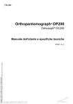
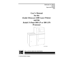
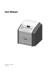
User Manual
Model: 8 0112 5 - 1 / 8 01125-2
UMF20000 Rev A
www.pancorp.com | 800.654.2027
Table of Contents
Introduction ______________________________________________________________________________3-5
Purpose ___________________________________________________________________________________________ 3
Statement of Compatibility ___________________________________________________________________________ 3
Safety Standards ____________________________________________________________________________________ 4
Warning of Voltage Regulators ________________________________________________________________________ 5
X-Ray Shielding Requirements ________________________________________________________________________ 5
Intended Use _______________________________________________________________________________________ 5
Warning Statements _________________________________________________________________________________ 5
Symbols & Definitions _______________________________________________________________________ 6
PC-3000 Components _______________________________________________________________________ 7
PC-3000 Control Panel _______________________________________________________________________ 8
PC-3000 Pre-Patient Setup _________________________________________________________________9-11
Prepare The Patient ________________________________________________________________________________ 10
Position The Patient ________________________________________________________________________________ 11
PC-3000 Patient Positioning _____________________________________________________________________ 11-12
Set The kVp _______________________________________________________________________________________ 11
Position The Patient ________________________________________________________________________________ 11
Recheck Patient Positioning _________________________________________________________________________ 12
Take The Exposure _________________________________________________________________________________ 12
Release The Patient ________________________________________________________________________________ 12
Process The Film ___________________________________________________________________________________ 12
PC-3000 TMJ Pre-Patient Setup __________________________________________________________________ 13-15
Prepare The Patient ________________________________________________________________________________ 14
Position The Patient ________________________________________________________________________________ 15
PC-3000 TMJ Patient Positioning_________________________________________________________________ 15-16
Set The kVp _______________________________________________________________________________________ 15
Position The Patient ________________________________________________________________________________ 15
Recheck Patient Positioning _________________________________________________________________________ 16
Take The Exposure _________________________________________________________________________________ 16
Release The Patient ________________________________________________________________________________ 16
Process The Film ___________________________________________________________________________________ 16
Panoramic Radiography ______________________________________________________________ Appendix A
Darkroom Procedures________________________________________________________________ Appendix B
Preventative Maintenance Guide ______________________________________________________ Appendix C
PC-3000 Labeling ___________________________________________________________________ Appendix D
PC-3000 Specifications _______________________________________________________________ Appendix E
PC-3000 Space Requirements _________________________________________________________ Appendix F
PC-3000 (MVT1000) _________________________________________________________________ Appendix G
2
Introduction
Purpose
Panoramic Corporation provides this printed manual as a
guide for the operation of the PC-3000 dental panoramic
X-ray machine.
The PC-3000 will enable the user to take panoramic X-ray
images.
It is imperative that this equipment be installed, serviced, and
used by personnel familiar with the precautions required to
prevent excessive exposure to both primary and secondary
radiation. This equipment features protective designs for
limiting both the primary and secondary radiation produced
by the X-ray beam. However, design features cannot prevent
carelessness, negligence, or lack of knowledge.
Only personnel authorized by Panoramic Corporation are
qualified to install and service this equipment. Any attempt to
install or service this equipment by anyone not so authorized
will void the warranty.
Statement of Compatibility - January 1, 1988
Please address any comments/questions concerning this statement of compatibility to:
Panoramic Corporation • 4321 Goshen Road • Fort Wayne, IN 46818 USA
The only components compatible with the PC-3000 are those supplied with the machine.
Regardless of possible statements made by other manufacturers, no one is authorized or certified to make additions or
deletions to this machine. Only the combination of components delivered with the machine is certified compatible by the
manufacturer. As compatible accessories become available, Panoramic Corporation will certify them as compatible and make
them available to the user.
Statement of Compliance - December 17, 2004
The PC-3000 conforms to the following specifications:
X-ray Generator type: Single phase, half-wave, self rectified, center-grounded in accordance with
IEC 60601-2-7:1998
3
Introduction
Safety
(Class B Device; Shock, Fire, Casualty)
• IEC 60601-1 Medical Electrical Equipment - Part 1: General Requirements for Safety
• IEC 60601-1:1998 + A1:1991 + A2:1995 Medical electrical equipment - Part 1-1: General requirements for safety
Collateral standard: Safety requirements for medical electrical systems
• IEC 60601-2-7:1998 Medical electrical equipment - Part 2-7: Particular requirements for the safety of high-voltage
generators of diagnostic X-ray generators
• IEC 60601-2-28:1993 Medical electrical equipment - Part 2: Particular requirements for the safety of X-ray source
assemblies and X-ray tube assemblies for medical diagnosis
• IEC 60601-2-32:1994 Medical electrical equipment - Part 2: Particular requirements for the safety of associated
equipment of X-ray equipment
• EN 60601-1:1990 + A1:1993 + A2:1995 + A3:1996 Medical electrical equipment - Part 1-1: General requirements for
safety - Collateral standard: Safety requirements for medical electrical systems
• CAN/CSA C22.2 NO. 601-1-M90 + A1:1994 + A2:1998 Medical Electrical Equipment - Part 1: General Requirements for
Safety
X-Ray Evaluation
• IEC 60601-1-3:1994 Medical electrical equipment - Part 1: General requirements for safety - 3. Collateral standard:
General requirements for radiation protection in diagnostic X-ray equipment
Software Review
• IEC 60601-1-4:1996 + A1:1999 Medical electrical equipment - Part 1-4: General requirements for safety - Collateral
Standard: Programmable electrical medical systems
EMC
(Class B Device):
• EN 60601-1-2:2001 (IEC 60601-1-2:2001) Medical electrical equipment - Part 1-2: General requirements for safety Collateral standard: Electromagnetic compatibility - Requirements and tests
• EN 55011:1998 + A1:1999 + A2:2002 Industrial, scientific and medical (ISM) radio-frequency equipment - Radio
disturbance characteristics - Limits and methods of measurement
• EN 61000-3-2:2000 Electromagnetic compatibility (EMC) - Part 3-2: Limits - Limits for harmonic current emissions
(equipment input current <= 16 A per phase)
• EN 61000-3-3:1995 + A1:2001 Electromagnetic compatibility (EMC) - Part 3-3: Limits - Limitation of voltage changes,
voltage fluctuations and flicker in public low-voltage supply systems, for equipment with rated current <= 16 A per
phase and not subject to conditional connection
• EN 60601-1-2:2001 (IEC 60601-1-2:2001) Electromagnetic Compatibility - Requirements and Tests
• EN 61000-4-2:1995 + A1:1998 + A2:2001 (IEC 1000-4-2) Electromagnetic compatibility (EMC)- Part 4-2: Testing and
measurement techniques - Electrostatic discharge immunity test
• EN 61000-4-3:2002 (IEC 1000-4-3) Electromagnetic compatibility (EMC) - Part 4-3: Testing and measurement
techniques - Radiated, radio-frequency, electromagnetic field immunity test
• EN 61000-4-4:1995 + A1:2001 + A2:2001 (IEC 1000-4-4) Electromagnetic compatibility (EMC) - Part 4-4: Testing and
measurement techniques - Electrical fast transient/burst immunity test
• EN 61000-4-5:1995 + A1:2001 (IEC 1000-4-5) Electromagnetic compatibility (EMC)- Part 4-5: Testing and
measurement techniques - Surge immunity test
• EN 61000-4-6:1996 + A1:2000 (IEC 1000-4-6) Electromagnetic compatibility (EMC) - Part 4-6: Testing and
measurement techniques - Immunity to conducted disturbances, induced by radio-frequency fields
• EN 61000-4-8:1993 + A1:2001 (IEC 1000-4-8) Electromagnetic compatibility (EMC) - Part 4-8: Testing and
measurement techniques - Power frequency magnetic field immunity test
• EN 61000-4-11:1994 + A1:2001 (IEC 1000-4-11) Electromagnetic compatibility (EMC) - Part 4-11: Testing and
measurement techniques - Voltage dips, short interruptions and voltage variations immunity tests
4
Introduction
Voltage Regulator Warning
Do not plug this machine into ANY voltage regulating device. Contact Panoramic Corporation with any questions regarding this.
X-ray Shielding Requirements
The requirements for panoramic and cephalometric shielding for building, operator, and patient, depend on state and local
regulations. Contact your state Department of Health for compliance information. Compliance could involve a blueprint review,
facility check, wall construction, film badge implementation, remote switch installation, and/or a lead apron. It is beyond the
scope of this manual to advise on these regulations.
Intended Use
An extraoral source X-ray system is an AC-powered device that produces X-rays and is intended for dental radiographic examination
and diagnosis of diseases of the teeth, jaw and oral structures.
Warning Statements
Warning: This X-ray unit may be dangerous to patient and operator unless safe exposure and operating instructions are observed.
During installation, machine is leveled to the floor. Do not move/transport the machine before contacting Panoramic Corporation
Service Department at (800)654-2027.
Notice: Ground reliability can only be acheived when this equipment is connected to a hospital only or hospital grade receptacle.
The use of accessory equipment not complying with the equivalent safety requirements of this equipment may lead to a reduced
level of safety of the resulting system. Consideration relating to the choice of accessory equipment shall include:
•
use of the accessory in the patient vicinity
•
evidence that the safety certification of the accesory has been performed in accordance to the appropriate IEC 60601-1
and/or IEC 60601-1-1 harmonized national standard.
Portable and mobile RF Communications equipment can affect medical electrical equipment.
Original document created in English.
Panoramic Corporation requires anyone moving or transporting their machine to contact the Service Department at
(800) 654-2027.
5
Symbols and Definitions
SYMBOLS
~
Alternating Current
Type B Equipment
Attention, Consult Accompanying Documents
I
O
On (power: connection to the mains)
Off (power: disconnection from the mains)
Dangerous Voltage
Protective Earth (ground)
Environmental Specifications
Operating Temperature:
Storage/Transportation Temperature:
Operating Humidity:
Storage/Transportation Humidity:
Operating Altitude:
Storage/Transportation Altitude:
10oC to 40oC (50oF to 105oF)
-25oC to 70oC (-13oF to 158oF)
80% maximum relative humidity, noncondensing
80% maximum relative humidity, noncondensing
15,000 ft (4,500 m) maximum
15,000 ft (4,500 m) maximum
Cleaning and Disinfection
The following parts on the PC-3000 come into contact with the patient during normal operation:
Black Chinrest
Temple Supports
Forehead Support
Handles
Use 70% Isopropyl Alcohol or Germicidal cloths (or equivalent) to clean and disinfect these parts.
Do not attempt to clean any parts while machine is switched on.
Mode of Operation
Continuous operation with short time loading.
Electrical Safety
Class I, Type B Applied Parts
Equipment is classified as ordinary equipment (enclosed equipment without protection against ingress of water).
Equipment not suitable for use in the presence of FLAMMABLE ANESTHETIC MIXTURE WITH AIR or WITH OXYGEN or
NITROUS OXIDE.
6
PC-3000 Components
Top Cover
Rotating Arm
Temple Supports
Forehead Support
Tubehead
Mirror
Control Panel
Film Drum/Cassette
Chinrest
Exposure Switch
Handles
Base
7
PC-3000 Control Panel
Exposure Indicator
Allows user to
select function or
increase value
Allows user to
select function or
decrease value
Allows you to
scroll to the next
screen
Accepts flashing
value
Allows you to
move back one
screen, and after
exposure allows
user to reset the
rotating arm.
Turns machine on
and off
Moves machine up
in the user mode
and scrolls up the
menus in service
mode
Moves machine
down in user
mode and scrolls
down the menus
in service mode
8
PC-3000 Pre-Patient Setup
1. In a lighttight darkroom, load a panoramic film in the cassette
sleeve between the intensifying screens.
2. Press POWER on the front of the control panel.
The screen will now display:
PANORAMIC
CORPORATION
3. Press MODE
The screen will now display:
SELECT OPERATION
PAN L
(Select from TMJ L, TMJ R, Pan L or Pan R)
To scroll, press the Adjust buttons (+) , (-) to select the
function you wish to use.
4. Press ENTER after the selection is made.
5. Press MODE to move to the next screen
The screen will now display:
ARM NOT POSITIONED
or
ARM POSITIONED
6. If not positioned, press ENTER. The rotating arm will now reset
to the “home” position for the operation you have selected.
7. Press MODE to move to the next screen
The screen will now display your selected operation:
PAN L
KVP: 80.0 (the number will be flashing)
8. Loosen the knob on the rear of the film drum.
9. Load a film cassette sleeve on the film drum.
a. Place the loaded cassette sleeve on the film drum with the
lower edge of the cassette sleeve resting on the lower lip of
the film drum.
b. Attach the vertical velcro at the end of the cassette sleeve
to the mating velcro on the end of the film drum. Ensure the
cassette sleeve is flat against the film drum.
c. Attach the velcro tab of the cassette sleeve to the mating
velcro on the center of the film drum.
d. The display will indicate which side (patient’s) the film drum
will reset and start. Align the pointer on the rear of the
film drum to the appropriate mark. If the display is set for
Panoramic L, align the pointer to L1. If the display is set for
Panoramic R, align the pointer
to R1.
e. Tighten the film drum knob
on the rear of the film drum.
Note: The film drum will rotate with
increased friction after the film
drum knob is tightened. Manual
rotation, while the knob is tight,
should be avoided to prevent
abnormal wear.
9
PC-3000 Pre-Patient Setup
10. Using the knob at the rear of the forehead support, adjust
the forehead support toward the mirror to allow room for
positioning the patient.
11. Slide the temple supports apart to allow room for
positioning the patient’s head.
12. Using the UP/DOWN switch on the control panel, adjust
the chinrest arm until it is slightly higher than the patient’s
chin. This will ensure that the patient stands up as straight as
possible.
13. If a stool is to be used, place the stool so that the seat is
centered under the chinrest. This will help ensure that the
patient’s neck is straight.
Prepare The Patient
1. Ask the patient to remove any metal objects, such as glasses,
earrings, removable dentures, hearing aids, hair pins, neck
chains, bib chains, and collar zippers from their head and neck
area. These objects can prevent X-rays from reaching the film,
causing poor diagnostic-quality images.
2. If a lead apron is used, and a panoramic poncho is not
available, place the lead apron on the patient’s back. Ensure
that it does not cover the back of the neck. As the tubehead
rotates around the patient, the X-rays pass through the head
at a slight upward angle. This allows the X-ray beam to pass
through the skull more efficiently by avoiding the denser area
of the patient’s skull.
3. Guide the patient into the PC-3000. Use the UP/DOWN
switch on the control panel to adjust the chinrest arm until it
is slightly higher than the patient’s chin. This will ensure that
the patient is standing up as straight as possible.
Caution: It is the responsibility of the operator to ensure
no obstructions exist during column movement due
to surroundings and/or patient. Movement can be
terminated by releasing the UP/DOWN buttons.
4. Have the patient hold onto the handles and move his/her
feet under the chinrest. This will help ensure that the patient’s
neck is straight.
5. Place the appropriate chinrest on the permanent, black
chinrest on the chinrest arm:
a. Small Child – Removable, black plastic chinrest. Maybe
needed to allow the child’s forehead to reach the
forehead support.
b. Adolescent and Adult – No additional chinrest. Majority
of patients require no additional chinrest.
c. Edentulous – Removable, clear plastic chinrest. Aids
in centering and consistently positioning the patient.
10
PC-3000 Pre-Patient Setup
6. If the patient is not edentulous,
insert a disposable bite-guide in
the permanent, black chinrest.
Have the patient bite on the
disposable bite-guide. Ensure that
the bite-guide is centered between
the central incisors. For edentulous
patients, have the patient bite on a
1 1/2” cotton roll to keep the maxilla
and mandible separated.
Position The Patient
1. Place your hand at the base of the patient’s skull and apply
pressure vertically to stretch the neck while slowly lowering
the machine until the patient’s Frankfort Plane is horizontal
(parallel to the red guidelines on the temple supports).
The Frankfort Plane is the imaginary line from the middle of the
ear opening to the bottom of the eye orbit. A level Frankfort
Plane will ensure that the upper and lower anterior teeth are
in one vertical plane and will help stretch the patient’s neck
enough to allow X-rays to pass between the vertebrae.
2. Using the knob on the rear of the forehead support, adjust
the forehead support until it touches the patient’s forehead.
3. Center the patient’s head using the red line on the forehead
support. Turn the mirror to see the patient to verify centering.
4. Gently slide the temple supports against the patient’s head.
These will help keep the patient centered and measure the
width of the skull to determine the amount of kVp required
to penetrate the skull.
Set The kVp
1. Note which number the arrow points to on the kVp scale
decal on the outside of the temple support rod.
2. Press the Adjust +/- buttons to adjust the kVp setting per
the temple supports. Plus (+) will increase the reading, (-)
will decrease the reading. KVP range is 70.0-90.0 adjustable
by 2.5 increments.
3. Press ENTER once the correct kVp setting is selected to lock
in the value.
The screen will now display:
ADJUSTING KVP
4. Press MODE to move to the next screen. Exposure LED light
will illuminate to solid green and screen will now display:
PAN L
80.0 KVP
Press EXPOSURE.
11
PC-3000 Patient Positioning
Re-check Patient Positioning
1. Ensure that the:
a. patient’s chin is firmly seated on the chinrest
b. patient’s feet positioned directly beneath support
handles
c. patient’s head is centered
d. patient’s Frankfort Plane is horizontal
e. patient’s neck is stretched
f. patient’s forehead is resting on the forehead support
g. temple supports are against the patient’s head
h. control panel indicates proper kVp through temple
support rod
Take The Exposure
1. Instruct the patient to close his/her lips around the
disposable bite-guide, swallow, place his/her tongue on the
roof of his/her mouth, and remain still during the exposure.
This will help equalize tissue densities and help prevent
unwanted artifacts and blurring.
2. Depress exposure button, screen will display WARMUP IN
PROGRESS and have a slow beep (5-6 seconds). Exposure
will then start, LED light will now display on Control Panel
indicating Radiation is present and the rotating arm will
begin to rotate around the patient. When exposure is
complete, release the exposure button.
Caution: It is the responsibility of the operator to
ensure no obstructions exist during arm rotation due
to surroundings and/or patient. Movement can be
terminated by releasing the Exposure button.
Release The Patient
1. Slide the temple supports away from the patient’s head
to release the patient.
2. Raise bite guide.
3. Instruct the patient to step out of the machine.
4. The screen will now display:
PANORAMIC
CORPORATION
5. Press the RESET button and the machine will return to
the “home” position.
6. Dispose of bite guide.
Process The Film
1. Loosen the film drum knob on the rear of the film drum
and remove the cassette sleeve from the film drum.
2. Under lighttight darkroom conditions, process the film.
12
PC-3000 TMJ Pre-Patient Setup
A TMJ series is simply four two-second panoramic
images exposed on one film. The TMJ film will show the
patient’s right closed, right open, left open, and left closed
temporomandibular joints.
1. In a lighttight darkroom, load a panoramic film in the
cassette sleeve between the intensifying screens.
2. Press POWER on the front of the control panel.
The screen will now display:
PANORAMIC
CORPORATION
3. Press MODE.
The screen will now display:
SELECT OPERATION
TMJ L
(Select from TMJ L, TMJ R, Pan L or Pan R)
To scroll, press the adjust buttons (+)/(-) to select the
function you wish to use.
4. Press ENTER after the selection is made.
5. Press MODE to move to the next screen
The screen will now display:
ARM NOT POSITIONED
or
ARM POSITIONED
6. If not positioned, press ENTER. The rotating arm will now
reset to the “home” position for the operation you have
selected.
7. Press MODE to move to the next screen
The screen will now display:
TMJ R
KVP: 80.0 (the number will be flashing)
8. Loosen the knob on the rear of the film drum.
9. Load a film cassette sleeve on the film drum:
a. Place the loaded cassette sleeve on the film drum with
the lower edge of the cassette sleeve resting on the
lower lip of the film drum.
b. Attach the vertical velcro at the end of the cassette
sleeve to the mating velcro on the end of the film drum.
Ensure the cassette sleeve is flat against the film drum.
c. Attach the velcro tab of the cassette sleeve to the mating
velcro on the center of the film drum.
d. Align the pointer on the rear of the film drum to L1.
e. Tighten the film drum knob on the rear of the film drum.
Note: The film drum will rotate with increased friction after
the film drum knob is tightened. Manual rotation, while the
knob is tight, should be avoided to prevent abnormal wear.
13
PC-3000 TMJ Pre-Patient Setup
10. Using the knob at the rear of the forehead support, adjust
the forehead support toward the mirror to allow room for
positioning the patient.
11. Slide the temple supports apart to allow room for
positioning the patient’s head.
12. If a stool is to be used, place the stool so that the seat is
centered under the chinrest. This will help ensure that the
patient’s neck is straight.
Prepare The Patient
1. Ask the patient to remove any metal objects, such as glasses,
earrings, removable dentures, hearing aids, hair pins, neck
chains, bib chains, and collar zippers from their head and
neck area. These objects can prevent X-rays from reaching
the film, causing poor diagnostic-quality images.
2. If a lead apron is used, and a panoramic poncho is not
available, place the lead apron on the patient’s back. Ensure
that it does not cover the back of the neck.
As the tubehead rotates around the patient, the X-rays pass
through the head at a slight upward angle. This allows the
X-ray beam to pass through the skull more efficiently by
avoiding the denser area of the patient’s skull.
3. Guide the patient into the PC-3000. Use the UP/DOWN
switch on the control panel to adjust the chinrest arm until
it is slightly higher than the patient’s chin. This will ensure
that the patient is standing up as straight as possible.
4. Have the patient hold on to the handles and move his/
her feet under the chinrest. This will help ensure that the
patient’s neck is straight.
5. Place the appropriate chinrest on the permanent, black
chinrest on the chinrest arm:
a. Small Child – Removable, clear plastic chinrest. Aids
in centering and consistently positioning the patient.
b. Adult – Removable, clear plastic chinrest. Aids in
centering and consistently positioning the patient.
c. Edentulous – Removable, clear plastic chinrest. Aids
in centering and consistently positioning the patient.
14
PC-3000 TMJ Patient Positioning
Position The Patient
1. Place your hand at the base of the patient’s skull and apply
pressure vertically to stretch the neck while slowly lowering
the machine until the patient’s Frankfort Plane is horizontal
(parallel to the red guidelines on the temple supports).
The Frankfort Plane is the imaginary line from the middle of
the ear opening to the bottom of the eye orbit. A level Frankfort
Plane will ensure that the upper and lower interior teeth are
in one vertical plane and will help stretch the patient’s neck
enough to allow the X-rays to pass between the vertebrae.
2. Using the knob on the rear of the forehead support, adjust
the forehead support until it touches the patient’s forehead.
3. Center the patient’s head using the red line on the forehead
support. Turn the mirror to see the patient to verify
centering.
4. Gently slide the temple supports against the patient’s head.
These will help keep the patient centered and measure the
width of the skull to determine the amount of kVp required
to penetrate the skull.
Set The kVp
1. Note which number the arrow points to on the kVp scale
decal on the outside of the temple support rod.
2. Position Patient and get kVp reading from temple supports.
Place Cassette sleeve on Film drum, aligning the black line
with R1. Or L1, depending upon the side of the machine
that the film drum is on.
3. Press the Adjust +/- buttons to adjust the kVp setting per
the temple supports. Plus (+) will increase the reading, (-)
will decrease the reading. KVP range is 70.0-90.0 adjustable
by 2.5 increments.
4. Press ENTER once the correct kVp setting is selected to
lock in the value.
The screen will now display:
ADJUSTING KVP
5. Press MODE to move to the next screen.
The screen will now display:
TMJ R (1) 80.0 KVP
Press EXPOSURE
15
PC-3000 TMJ Patient Positioning
Re-check Patient Positioning
1. Ensure that the:
a. patient’s chin is firmly seated on the
chinrest
b. patient’s feet positioned directly beneath
support handles
c. patient’s head is centered
d. patient’s Frankfort Plane is horizontal
e. patient’s neck is stretched
f. patient’s forehead is resting on the
forehead support
g. temple supports are against the patient’s
head
h. control panel indicates proper kVp
through temple support rod
Take The Exposure
1. Instruct the patient to close his/her lips, swallow, place his/
her tongue on the roof of his/her mouth, and remain still
during the four exposures. This will help equalize tissue
densities and help prevent unwanted artifacts and blurring.
2. Depress exposure button, screen will display WARM UP IN
PROGRESS and have a slow beep (5-6 seconds). Exposure
will then start, LED light will now display on Control Panel
indicating Radiation present and the rotating arm will
begin to rotate around the patient. When exposure is
complete, release the exposure button, the rotating arm
will automatically return to the “home” position.
3. Align the film drum to position R2.
The screen will now display:
TMJ R (2) 80.0 KVP
Press EXPOSURE.
4. Depress exposure button, screen will display WARM UP
IN PROGRESS and have a slow beep. Exposure will then
start, LED light will now display on Control Panel indicating
Radiation present and the rotating arm will begin to rotate
around the patient. When exposure is complete, release
the exposure button, the rotating arm will automatically
return to the opposite side of the rotation for the other two
exposures.
The screen will now display:
ARM POSITIONING
5. Align the film drum to position L1.
The screen will now display:
TMJ L (1) 80.0 KVP
Press EXPOSURE
6. Depress exposure button,
screen will display WARM
UP IN PROGRESS and have a
slow beep. Exposure will then
start, LED light will now display
on Control Panel indicating
Radiation present and the
rotating arm will begin to
rotate around the patient.
When exposure is complete,
release the exposure button,
the rotating arm will automatically return
to the start position for the L side of exposure.
7. Align the film drum to position L2.
The screen will now display:
TMJ L (2) 80KVP
Press EXPOSURE
8. Depress exposure button, screen will display WARM UP
IN PROGRESS and have a slow beep. Exposure will then
start, LED light will now display on Control Panel indicating
Radiation present and the rotating arm will begin to rotate
around the patient. When exposure is complete rotating
arm will automatically return to the “home” position.
The screen will now display:
PANORAMIC
CORPORATION
Release The Patient
1. Slide the temple supports away from the patient’s head
to release the patient.
2. Instruct the patient to step out of the machine.
Process The Film
1. Loosen the film drum knob on the rear of the film drum
and remove the cassette sleeve from the film drum.
2. Under lighttight darkroom conditions, process the film.
16
Appendix
Panoramic Radiography
Panoramic Radiography has been in use for over 30 years.
In panoramic radiography, the X-ray source and film rotate
around the patient’s head at the same speed. Simultaneously,
the film rotates about its own axis.
X-rays are emitted from the tubehead in a very narrow vertical
band, pass through the patient’s head (where some are
absorbed), and strike the film cassette sleeve. Intensifying
screens are used inside the film cassette sleeve. The
intensifying screens glow whenever X-rays strike them, the
more X-rays striking the screen, the brighter the glow. Film,
which is sensitive to light, is placed between the intensifying
screens. The more light that is exposed to the film, the darker
the film is. Since the patient is between the X-ray source and
the film, the amount of X-rays that reach the film will vary
depending on the density of the patient’s anatomy. Dense
matter, such as bone, will absorb more of the X-rays than less
dense matter, such as tissue. Less X-rays reach the film when
striking the teeth, causing them to appear on the film as lighter
areas. More X-rays reach the film when striking tissue, causing
it to appear on the film as darker areas.
X-rays
Film Drum
Tubehead
Film
Cassette
Sleeve
In order to pass as many X-rays through the patient’s head as
possible, the tubehead is tilted at a slight upward angle to:
1. Move the dense portion of the skull out of the path of
the X-rays
2. Cause the upper and lower anterior root tips to be
aligned vertically
3. Stretch the vertebrae in the neck to allow the X-rays to
pass more efficiently through the vertebrae to expose
the anterior teeth
As the tubehead and film rotate around the patient, the film is
gradually exposed by a narrow vertical band. It is imperative
that the film is aligned to start at the correct position and that
nothing stops the film drum or tubehead from moving while
the exposure is being taken.
Appendix A
Darkroom Procedures
The darkroom must be lighttight. Extraoral (panoramic/cephalometric) film is more sensitive than intraoral (bite-wings) film to
light, and processing time and temperature.
Manual Processing
• Lighttight darkroom
• Dip tanks
• Timer
• Developer and fixer solutions
• Film Hanger
• Water supply and drain
• Safelight (GBX-2 filter or equivalent, 15 W bulb or less and at least 4’ from film)
• Thermometer
1.
2.
3.
4.
5.
6.
Prepare developer and fixer solutions according to the solution’s directions.
Verify developer temperature.
Under safelight conditions, remove the exposed film from the cassette sleeve and attach it to a film hanger.
Set the timer based on the developer temperature and the processing chart.
Immerse the film quickly into the developer and agitate it vigorously for only 5 seconds to dislodge any air bubbles.
When the timer sounds, remove the film from the developer and immediately rinse it with water for 30 seconds while agitating
it. Do not allow the excess developer to drain back into the developer tank.
7. Immerse the film into the fixer and agitate it for 5 seconds every 30 seconds. Allow the excess fixer to drain back into the
fixer tank.
8. Immerse the film in the water wash tank and rinse it thoroughly.
9. Dry the film at room temperature or in a drying cabinet.
Automatic Processing
A thermometer should be present to periodically verify the temperature. It is imperative that the processor’s maintenance
schedule is followed thoroughly.
Manual Processing
Film Type
T-MAT
(for use
with Lanex
screens)
Developer
Temperature Time
68º F 20.0º C
72º F 22.0º C
76º F 24.5º C
80º F 26.5º C
8 min
7 min
5 min
4 min
Automatic
Processing
Rinse
Fixer
Wash
30 sec
60º F 15.5º C
to
85º F 29.5º C
2-4 min
60º F 15.5º C
to
85º F 29.5º C
5 min
60º F 15.5º C
to
85º F 29.5º C
82º F 28.0º C 5.5 min
83º F 28.5º C 4.5 min
85º F 29.5º C 4 min
Note: Extraoral film requires more frequent solution replenishment than intraoral film. One ounce of chemicals are typically
required for replenishment for every 75 intraoral, 3 panoramic, or 2 cephalometric films.
Appendix B
Darkroom Procedures
Darkroom Light Leak Test
Extraoral film is more sensitive to light than intraoral film. The purpose of the intensifying screens inside of the cassette sleeve
is to convert the X-ray energy into light, thus exposing the film. While the light sensitivity of the film allows a very small amount
of radiation to expose the film, it also can pose a problem if the darkroom is not completely lighttight. Small light leaks can
cause fogging of the film while handling and processing the film in the darkroom.
The following test should be performed in the darkroom under safelight conditions to ensure it is lighttight:
1. Remove one sheet of extraoral film from the box.
2. Lay it on the counter in the darkroom under normal darkroom conditions.
3. Place a couple of coins, a pair of scissors, or any other opaque object on top of the film.
4. Wait for two minutes.
5. Process the film as usual.
The processed film should be clear. None of the objects should be visible on the film.
If any of the objects can be seen on the processed film, there is a light leak or other light source in the darkroom. The light leak
fogs the test film, everywhere except where the opaque objects are blocking the light. To find the light leak, turn all of the
lights off in the darkroom and inspect the darkroom for cracks around the door and ceiling tiles. Indicator lights on equipment,
such as stereos, and improper safelights can also cause fogging. Turn off all unnecessary equipment and the safelight and try
this test again.
Appendix B
Darkroom Procedures
It is recommended that the panoramic cassettes be loaded
with film just prior to use. Do not leave a film loaded in the
cassettes for an extended period of time. This will prevent
background radiation from prematurely exposing the film.
The film should be stored in a cool and dark place.
Loading The Panoramic Cassette
In a lighttight darkroom, open the flexible, panoramic cassette
sleeve and slowly remove the intensifying screens. Open the
screens on the counter and place a sheet of panoramic film on
top of one of the screens. Close the screens and slowly slide
them back into the cassette sleeve. Ensure that the hinged end
of the screens is placed into the cassette sleeve first and the
“TUBESIDE” decal is facing the same direction as the writing
on the outside of the cassette sleeve. Ensure that all excess
air is expelled from the cassette sleeve.
Note: Remove and discard the protective sheet from between
new intensifying screens before their first use.
Appendix B
Preventative Maintenance Guide
Panoramic Corporation strongly recommends a preventive maintenance be performed on your equipment at least every two
years. All service requests must be submitted through Panoramic Corporation’s Service Department by calling our toll-free
number at (800) 654-2027.
Panoramic has an extensive network of independent installation and service organizations throughout the U.S. and Canada
to install and service our products. The Independent Representatives have been specifically trained by our organization
in the service and installation of Panoramic products. We strongly recommend that you use one of our Independent
Representatives to service Panoramic products. To the extent you use third parties other than Independent Representatives
to service Panoramic products, we cannot accept responsibility or liability for any work performed by those third parties
and any resulting damages or liability attributable thereto. In no event shall Panoramic be liable to you or any other third
party for any direct, indirect, punitive, incidental, consequential or special damages or lost profits arising from, relating to or
connected with, the installation of or repair of a Panoramic product by someone other than an Independent Representative.
Always refer to your state and local regulations to determine how often to perform a preventive maintenance on your
equipment as the regulations may supersede manufacturers’ recommendation.
Owners of Panoramic Corporation X-Ray machines must call Panoramic Corporation Service Department for all reasons listed
below but not limited to:
-
Preventive maintenance at least every two years
Physical relocation of machine
Changing the power source to a different power source from original installation
Questions/Help related to compliance with your state, and local regulations regarding radiological equipment
Corrective Maintenance
Physical damage that may affect radiation safety
Interrupted movement, unusual noises, leaks, etc.
To schedule a preventive maintenance on your equipment contact the Service Department by dialing our toll-free number at
(800) 654-2027.
Appendix C
PC-3000 Labeling
Control Panel
Appendix D
Appendix E
PC-3000 Specifications
PC-3000 Specifications
Power Requirements
Model 801125-1: 105-125 VAC, 50/60 Hz, 10A
Model 801125-2: 100/230/240 VAC, 50/60 Hz, 10A
Generator Type
Single-phase, half-wave, self-rectified, center-grounded.
Duty Cycle
At 90 kVp/6 mA - One 12 second exposure every 5 minutes to a maximum of 30
exposures.
Tubehead Assembly
X-ray Tube
Brand X-Ray or K-Alpha
Rated Tube Potential Peak
100 kVp
Leakage Technique Factors
90 kVp/6 mA
Inherent Filtration
1 mm
Added Aluminum Filtration
1.8 mm
Total Filtration
2.8 mm
Manufacturer
Type
Focal Spot
Maximum Peak Voltage
Anode Heat Dissipation Rate
Anode Heat Storage Capacity
Brand X-Ray or K-Alpha
Peak Tube Potential
Tube Current
Exposure Time
± 12% over range of rated line voltage
Exposure Time
Measured with Engineered Systems & Design
Model XR201MS pulse counter.
Tube Current
Measured directly with a DC mA meter having
a basic accuracy of no less than ± 3%.
Peak Tube Potential
Measured using a computerized kVp
measurement system NeroMax Victorean.
System accuracy is ± 3% exclusive
of waveform, inherent filtration, and
reproducibility.
Maximum Line Current
Machine set at 90 kVp/6 mA
X-ray Tube
Statement of Deviation
Measurement
Techniques
Screen/Film Type
BX-4P0.5 or KAX-90-10-P
.5 mm x .5 mm
100 kVp
250 Watts
1 Watt=1.4 H.U./sec.
35 kJ
1 kJ=1400 H.U.
± 10% over line voltage
± 10% over line voltage
Kodak Ektavision with Kodak Ektavision G
Appendix E
PC-3000 Space Requirements
35"
23"
Physical Dimensions
35" W x 42" D x 91" H
Minimum Working Space
48" W x 48" D x 91" H
42"
32"
The PC-3000 weighs approximately 415 pounds and
is freestanding, requiring no extra support in the wall
or floor.
91" Maximum
58" Minimum
The factory configuration is shipped with the control
panel mounted on the patient's left side, unless
specified by the customer prior to shipping. The
control panel can be easily relocated to the right side
at the time of installation.
Note: The FDA requires that the technique factors
(kVp meter) be viewable during the exposure.
Appendix F
MVT 1000 Diagram
Model 801125-2 includes MVT1000 attached to the
rear of the machine. MVT1000 power cords must be
connected as shown.
MVT1000
MVT1000 power cord
to machine
MVT1000 power cord
to power source
Appendix G