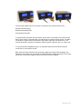
1
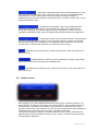
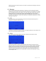
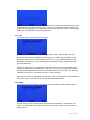
uniscan instruments BiStat 3200 Dual Potentiostat – Galvanostat OPERATING MANUAL Blank Page – Reverse side of front Cover BiStat 3200 Dual Potentostat - Galvanostat OPERATING MANUAL Issue 1.1 BiStat 3200 OPERATING MANUAL CONTENTS Section Page 1 SAFETY PRECAUTIONS 6 2 INTRODUCTION 9 3 HARDWARE DESCRIPTION 11 4 FRONT PANEL OPERATION 15 4.1 Display navigation 4.2 Using the keys 4.3 Main menu 5 CONNECTING 5.1 Connecting to a computer 5.2 Connecting to your electrochemical cell 6 SOFTWARE 6.1 6.2 6.3 6.4 6.5 6.6 7 UiEChem - Standard Electrochemical Techniques UiECorr - Standard Corrosion Techniques Custom Techniques Stand alone programming Installation Software Manual ACCESSORIES 7.1 Screened Multi Working Electrode Cable 8 CONNECTOR DETAILS 8.1 Cell connector detail. 8.2 dc power connector detail. 9 POWER SUPPLY 9.1 Power supply adapters 9.2 Fitting Adapters 15 16 17 21 21 21 23 23 23 23 24 24 24 25 25 27 27 28 29 29 29 10 SPECIFICATIONS 31 11 TECHNICAL SUPPORT 33 1 SAFETY PRECAUTIONS The BiStat 3200 Potentiostat - Galvanostat equipment described in this manual complies with the Low Voltage Directive (LVD) 72/23/EEC. To avoid injury to an operator or service technician the safety precautions given below, and throughout the manual, must be strictly adhered to whenever the equipment is operated, serviced or repaired. For specific operational details refer to the relevant section within this manual. The BiStat 3200 is designed solely for Potentiostat - Galvanostat measurement and should be used for no other purpose. The manufacturers and distributors accept no responsibility for accidents or damage resulting from any failure to comply with these precautions. INSTALLATION CATEGORY In compliance with the Low Voltage Directive (LVD) 72/23/EEC this equipment is designated as Installation Category: Cat II. GROUNDING To minimise the hazard of electrical shock it is essential that the equipment is connected to a protective ground whenever the power supply and/or separate measurement devices are connected, even if the equipment is switched OFF. FUSES Before switching on the BiStat 3200 check that any fuses accessible from the exterior of the equipment are of the correct rating. The rating of the a.c. line fuse must be in accordance with the voltage of the a.c. supply. Should any fuse continually blow, DO NOT insert a fuse of a higher rating. Switch the equipment OFF, clearly label it “Unserviceable” and inform a service technician. EXPLOSIVE ATMOSPHERES NEVER OPERATE the BiStat 3200, or any units connected to the equipment in a potentially explosive atmosphere. The BiStat 3200 is NOT „Intrinsically Safe‟ and could possibly cause an explosion. NOTES For guidance and protection of the user „Notes‟ appear throughout the manual. These highlight important information for the user‟s attention to prevent damage to the user or the equipment. DISPOSAL The BiStat 3200 instrument is marked with the crossed out wheelie bin symbol. At the end of its life the instrument should not be disposed of with conventional refuse. Please contact your supplier who will advise you on the correct method of disposal for your instrument. SAFETY PRECAUTIONS (…FROM PREVIOUS PAGE) SAFETY SYMBOLS For guidance and protection of the user, the following safety symbols appear on the equipment (where relevant): Symbol ! Meaning Caution (refer to accompanying documents). Caution, risk of electric shock. Earth (ground) TERMINAL. AVOID UNSAFE EQUIPMENT The equipment may be unsafe if any of the following statements apply: Equipment shows visible damage. Equipment has failed to perform the intended operation. Equipment has been subjected to prolonged storage under unfavourable conditions. Equipment has been subjected to severe physical stress. If in any doubt as to the serviceability of the equipment, do not use it. Get it properly checked out by a qualified service technician. LIVE CONDUCTORS When the equipment is connected to its measurement inputs or supply, the opening of covers, or removal of parts could expose live conductors. The equipment must be disconnected from all power and signal sources before it is opened for any adjustment, replacement. Maintenance or repair. Adjustments, maintenance or repair must be done by qualified personnel who should refer to the servicing manual. EQUIPMENT MODIFICATION To avoid introducing safety hazards, never install non-standard parts in the equipment, or make any unauthorised modification. To maintain safety, always return the equipment to your supplier for service and repair. ELECTROLYTES Correct handling and disposal of the electrolyte, in accordance with manufacturer‟s instructions is essential for safe operation of the system. Page 8 of 33 Chapter 2 Introduction 2 INTRODUCTION The potentiostat – galvanostat has become an accepted and widely used instrument for the study of electrochemistry and corrosion mechanisms. The BiStat 3200 provides the facilities found in a traditional lab based instrument, in a dual design. The BiStat 3200 operates as two independent isolated instruments or as a BiPotentiostat or Bi-Galvanostat. The instrument may be operated from its front panel using the dual keypads and LCD displays or connected to a Windows™ based personnel computer. When connected to a personnel computer the instrument is supported by the UiEChem and UiECorr software applications for Electrochemistry and Corrosion research respectively. The instrument may also be controlled from third party programming environments such as Visual Basic, Labview etc. using the optional activeX control interface. Page 9 of 33 Chapter 3 Hardware Description 3 HARDWARE DESCRIPTION Figure.1 BiStat 3200 Instrument Hardware Features. Page 11 of 33 1. Power Connector. This connection is used to connect the supplied power adapter to the BiStat 3200. The power adapter powers the instrument continuously from mains power. Only the supplied power supply should be connected to this connector. Details of the dc power connector pins can be found in the “Connector details” section of this manual. 2. USB. This connection is used to connect the BiStat 3200 to a host computer. The BiStat 3200 is normally connected directly to a standard USB port of a personal computer. The BiStat 3200 can be connected via a USB hub provided the maximum USB cable & hub specifications are not exceeded. Please note that the BiStat 3200 employs an internal USB hub, which must be taken into account when considering the maximum number of nodes and cable lengths from the host computer. 3. Power Switch This toggle switch is used to switch the instrument on & off. When switched on the LCD displays show the instrument parameters, after a few seconds. 4. Left key 1 & 2. This key or button is used to enter information into the BiStat 3200 when the instrument is being used stand-alone. The Left key is generally used to navigate through menu items or available selections. The function of this key is dynamic and follows the adjacent icon on the display. The 1 & 2 nomenclature refers to the two potentiostats respectively. 5. Centre key 1 & 2. This key or button is used to enter information into the BiStat 3200 when the instrument is being used stand-alone. The Centre key is generally used to select menu items or OK options. The function of this key is dynamic and follows the adjacent icon on the display. The 1 & 2 nomenclature refers to the two potentiostats respectively. 6. Right key 1 & 2. This key or button is used to enter information into the BiStat 3200 when the instrument is being used stand-alone. The Right key is generally used to navigate through menu items or available selections. The function of this key is dynamic and follows the adjacent icon on the display. The 1 & 2 nomenclature refers to the two potentiostats respectively. 7. LCD Display 1 & 2. The display shows all the relevant information to the operator. The display also provides menu icons and labels for identifying the three user keys. The 1 & 2 nomenclature refers to the two potentiostats respectively. 8. I (current) overload LED 1 & 2. The I overload LED indicates when the measured current amplitude is too high for the selected current range. No meaningful data is measured when this LED is illuminated. The 1 & 2 nomenclature refers to the two potentiostats respectively. 9. E (potential) overload LED 1 & 2. The E overload LED indicates when the output amplifier (CE) potential amplitude is too high for the instrument. No meaning full data is measured when this LED is illuminated. The 1 & 2 nomenclature refers to the two potentiostats respectively. Page 12 of 33 10. Cell connector 1 & 2. The cell connector provides the electrical connections between the BiStat 3200 and the electrochemical cell. The BiStat 3200 is shipped with a standard three-electrode cell cable, which connects to this connector. The standard screened cell cable has three connections, WE Working Electrode, RE- Reference Electrode and CE Counter Electrode. There are several alternative cell cables available for the BiStat 3200, which suit different applications. Please consult your distributor for details. The cable supplied is a screened cable for use with single electrode cells. Details of the Cell connector pins can be found in the “Connector details” section of this manual. The 1 & 2 nomenclature refers to the two potentiostats respectively. Page 13 of 33 Chapter 4 Front panel operation 4 FRONT PANEL OPERATION The BiStat 3200 operates in several modes; the simplest is from the front panel controls. In this mode of operation the BiStat 3200 is able to apply static potentials (Potentiostat) or currents (Galvanostat) and measure a static potentials and currents. The options are set by navigating through an interactive menu system and the results are displayed on the display. The dual channel facilities of the instrument enable it to have independent set & measurement parameters for each of the two channels. It is possible for the BiStat 3200 to have a User Program loaded, which runs in place of the standard front panel operation. In this case the following description of the operation of the instrument does not apply. 4.1 DISPLAY NAVIGATION Instrument Display after power up The image above shows the LCD display when the instrument is first switched on. The display shows the real time status of the instrument. The information may be broken down into the following sections: – Indicates that the first of the five available WE (Working Electrode) connections is selected. This may be changed in the “Cell” menu. Please note that the standard cable with a single WE connection is connected to “1”. – Indicates that the cell is switched off. The cell may be switched “On” in the “Cell” menu. When the cell is switched off the CE (Counter Electrode) connection is isolated. The potential difference between RE (Reference Electrode) and WE (Working Electrode) is still measured in the “Cell E =” parameter. When the cell is off no potential or current may be applied to the cell. – Indicates that the instrument is in Potentiostatic mode. Alternatively the instrument may be in Galvanostatic (G-Static) or ZRA Mode. The mode may be set in the “Mode” menu. Page 15 of 33 – Indicates the applied potential which would be applied to the cell if the cell were “On” rather than “Off” as it is in the switch on state. The applied potential may be set in the “Set E” menu option. Please note that if the instrument were in Galvanostat mode, then this indication would display “Set I = 0.000A” and the “Set E” menu would be changed to “Set I”. – Indicates the cell potential. That is the potential difference between the RE & WE connections. In this example none of the cell connections are connected to anything. Since the RE input is very high impedance, it “floats” to a value beyond the measurable range, hence the display shows OVER instead of a voltage value. – Indicates the current in the cell WE connection. In this example the cell is off and the WE connection is not connected to anything, thus the value “floats” picking up electromagnetic interference. The displayed value is scaled with the selected current range. In this case the instrument is on the 10mA current range. - Indicates that the left menu key or button will scroll the centre menu option one place to the left. - Indicates that the centre key or button will select the “Set E” menu option. There are several menu options which are detailed below. - Indicates that the right menu key or button will scroll the centre menu option one place to the right. 4.2 USING THE KEYS Each channel (1 & 2) of the BiStat 3200 has three user keys to control its operation, Left, Centre & Right. The function of these keys is context sensitive. The immediate function of the three keys is indicated on the display by a key word or icon adjacent to each key. In general the centre key is the “Selection” or “OK” key and the left and right keys navigate the available options, or scroll through numerical or alphabetic characters. In the photo example the centre key is used to select the “Set E” option, whilst the left & right keys scroll round the different centre key menu options. The arrow icons indicate the left and right key operations. Page 16 of 33 Please note that each channel may be “put to sleep” by pressing and holding the centre key for a few seconds. 4.3 MAIN MENU When the BiStat 3200 has been switched on it displays a screen showing the real time potential and current values of the electrochemical cell at the top of the display. The bottom line of the display shows the menu options. The menu options are scrolled round using the left and right keys. The selected menu option is displayed adjacent to the centre key. Pressing the centre key invokes the selected option. Following switch on the “Set E” is the first menu option displayed. The main menu options are considered in detail below, in order, following the “right” key:4.3.1 Set E If the BiStat 3200 is set to Potentiostatic mode then the Set E (Set Potential) option is available. The potential is defined in volts. The left key increments the selected character. The right key selects the next character. The centre “OK” key accepts the defined potential. 4.3.2 I Range The I Range (Current range) selection defines the maximum and minimum current measuring capability of the BiStat 3200. The left and right keys increment or decrement the current range. The centre “OK” key selects the range. The current range should be chosen such that the required measured (or applied) current is comfortably in the range. If the current range is set too high, then the measured current will be lost in the IE converter noise floor. If the current range is set too low the IE converter will overload in the event that the current exceeds the maximum. A current overload is indicated by the I overload LED on the front of the instrument. The top current range is “Auto” Page 17 of 33 if this is selected then the instrument will automatically increment and decrement the current range based on the measured current value. This auto current range setting is applied only to the front panel operation of the instrument and does not relate to any auto current ranging which may be implemented in controlling software. 4.3.3 Cell This menu option controls the cell connection. The left and right keys scroll through the three options “Cell”, “Cell Number” and “OK”. When the “Cell” option is highlighted, pressing the centre “select” key repeatedly scrolls though the options for the “Cell”, these are “Off” and “On”. This enables the CE (Counter Electrode) connection to your cell and allows the instrument to apply potential to the WE (Working Electrode) When the “Cell Number” is highlighted, pressing the centre “select” key repeatedly scrolls thought the options for the “Cell Number”, these are 1,2,3,4 & 5. The Cell number refers to the WE (Working Electrode) connection on the instruments “Cell” connector. The standard cable WE connection is connected to the first “1” WE connection. When the “OK” option is highlighted, the values for “Cell” & “Cell Number” are accepted and the screen closes, and returns to the normal instrument status window. 4.3.4 Mode The mode option allows selection of Potentiostat, Galvanostat or ZRA operation modes. The left and right keys scroll though the three options “Potentiostat”, “Galvanostat” and “ZRA”. The centre “OK” key confirms the selection and returns to the normal instrument status window. Page 18 of 33 In Potentiostatic mode a constant potential is defined and a variable current is measured. The Potentiostat maintains the working electrode (WE) at constant potential with reference to the reference electrode (RE). The potentiostat achieves this by controlling the potential of the counter electrode (CE). In Galvanostat mode a constant current is defined and a variable potential is measured (with reference to RE). The Galvanostat maintains a constant current through the working electrode by controlling the potential of the counter electrode (CE). In ZRA mode the current between two electrodes connected to the WE & CE connections is measured. The RE potential may also be measured, but does not affect any applied potential. In ZRA mode it is normal for the applied potential to be zero, such that both electrodes are effectively connected together. In any of the operation modes care should be taken in the correct selection of current range, to achieve optimum results. 4.3.5 Contrast This menu option sets the contrast of the LCD display. It should be set to give the most pleasing image on the display. The left and right keys increment and decrement the contrast value from zero to 100. The display contrast can be observed whilst changing the value. The centre “OK” key accepts the contrast value and returns the instrument back to its normal status display. 4.3.6 Backlight This menu option controls the blue LED backlight operation of the display. The left and right keys increment and decrement the Backlight value from “Off” to “Always ON”. If a time values such as 10 seconds is selected then the display backlight will turn off when no key is pressed for 10 seconds. The backlight will turn back on when a key is pressed. The centre “OK” key accepts the contrast value and returns the instrument back to its normal status display Page 19 of 33 Chapter 5 Connecting 5 CONNECTING In this section we will show how to connect the BiStat 3200 to the host computer and to your electrochemical cell. 5.1 CONNECTING TO A COMPUTER The BiStat 3200 is connected to a host computer using the USB cable supplied. The software supplied with the instrument should be installed before the instrument is connected to the computer, so that the instrument driver is preloaded on the computer. When the driver is preloaded the computer will automatically install the instrument without user interaction. If the driver is not installed, the user will need to manage the driver installation which could result in the instrument not being installed correctly. The BiStat 3200 is normally connected directly to a standard USB port of a personal computer. The BiStat 3200 can be connected via a USB hub provided the maximum USB cable & hub specifications are not exceeded. Please note that the BiStat 3200 employs an internal USB hub, which must be taken into account when considering the maximum number of nodes and cable lengths from the host computer. 5.2 CONNECTING TO YOUR ELECTROCHEMICAL CELL The BiStat 3200 is supplied with two screened three-electrode cell cables, one for each of the two channels. This cable has a 15 pin “D” connector on one end and three cables with 4mm plugs and optional crocodile clips. The 15 pin D connectors should be connected to the “Cell 1” and “Cell 2” connectors on the front panel of the instrument. Page 21 of 33 The three flying leads from each cell are connected to your electrochemical cell: Working electrode (WE). Reference Electrode (RE). Counter Electrode (CE). In a typical three-electrode electrochemical cell the WE is connected to the system under study, which maybe a milli-electrode, microelectrode or electrochemical sensor. The RE is connected to a glass reference electrode, Silver/Silver Chloride, Sat Calomel etc. The Counter electrode is typically connected to platinum gauze, platinum wire or a carbon rod. In a two-electrode arrangement there is no separate reference electrode and the RE connection is connected to the CE. Both channels of the instrument are electrically isolated from each other (floating). The instrument can therefore be connected as a BiPotentiostat or BiGlavanostat by connecting the two CE connections together and the two RE connections together. Page 22 of 33 Chapter 6 Software 6 SOFTWARE The BiStat 3200 is supported by the UiEChem and UiECorr software applications for Windows™. This software runs on a personnel computer. The UiEChem software provides standard electrochemical techniques, whilst the UiECorr software provides standard corrosion techniques. 6.1 UIECHEM - STANDARD ELECTROCHEMICAL TECHNIQUES The UiEChem software application provides many standard electrochemical techniques including: Chronoamperometry. Linear Voltammetry. Cyclic Voltammetry. Squarewave Voltammetry. Normal pulse Voltammetry. Differential pulse Voltammetry. Chronopotentiometry. 6.2 UIECORR - STANDARD CORROSION TECHNIQUES The UiECorr software application provides many standard corrosion techniques including: ECorr vs. Time. Galvanostatic Polarization. Linear Polarization Resistance. Potentiodynamic Polarization. Potentiostatic Polarization. Tafel. Zero Resistance Ammetry. 6.3 CUSTOM TECHNIQUES The Windows™ software applications provide a facility to implement custom techniques by programming macro experiments. This facility gives direct control of the advanced BiStat 3200 waveform generator and data acquisition features and allows the custom experiment to be displayed on a user defined window template. Please contact your distributor for help with macro experiments. Page 23 of 33 6.4 STAND ALONE PROGRAMMING The Windows™ software applications provide a facility to implement standalone programming of the BiStat 3200. In this mode the BiStat 3200 stores a user defined program which controls the instrument actions and display. The BiStat 3200 will execute this user program in place of the normal Potentiostat – Galvanostat panel control. Please contact your distributor for help with macro experiments. 6.5 INSTALLATION The Windows™ software is normally supplied on CD-ROM. To install the software locate the “Setup.exe” on the CD and run it. Loading the CD on a Windows system should cause the Set-up to execute automatically. Please note that the software should be installed before the hardware is connected to your computer so that the instrument driver software is pre installed. 6.6 SOFTWARE MANUAL The Windows™ software manual is included with the software in the form of on line help. See the “Help” – “Contents” menu in the software application. Page 24 of 33 Chapter 7 Accessories 7 ACCESSORIES There are several accessories available for the BiStat 3200. Several more accessories are planned for the BiStat 3200; please contact your distributor for the latest information. 7.1 SCREENED MULTI WORKING ELECTRODE CABLE A five WE connection screened multi electrode cable is available for your BiStat 3200. This allows up to five WE connections to be addressed sequentially. Page 25 of 33 Chapter 8 Connector Details 8 CONNECTOR DETAILS 8.1 CELL CONNECTOR DETAIL. The detail of the 15way female D connector used for the BiStat 3200 cell connections are given here. There are several connections on the connector, which are capable of causing damage to the BiStat 3200 if connected incorrectly. Please consult your distributor for any advanced connection arrangements before attempting modifications. 8.1.1 Cell Connector Pin description 8.1.2 Pin description Pin 1. WE1 First Working Electrode. Pin 2. WE2 Second Working Electrode. Pin 3 WE3 Third Working Electrode. Pin 4 WE4 Fourth Working Electrode. Pin 5 WE5 Fifth Working Electrode. Pin 6 VAux1 (Auxiliary voltage input +/- 2V. ref Analog Ground, special ground considerations). Pin 7 RE Reference electrode. Pin 8 CE Counter Electrode. Pin 9 Analog ground. (Reserved do not connect, do not connect to Digital ground). Pin 10 +5V (Reserved do not connect, very limited output current capability). Pin 11 Cell Txd (I2C bus connection for peripherals. Reserved do not connect). Pin 12 Cell Rxd (I2C bus connection for peripherals. Reserved do not connect). Pin 13 Digital Ground (earth, use to screen input cables. Do not connect to Analog ground). Pin 14 +12V supply for peripherals, very limited current capability (Reserved do not connect). Page 27 of 33 Pin 15 -12V supply for peripherals, very limited current capability (Reserved do not connect). 8.2 DC POWER CONNECTOR DETAIL. Pin Description DGnd – Digital ground. +VExt – External power (positive). Page 28 of 33 Chapter 9 Power Supply 9 POWER SUPPLY The BiStat 3200 is shipped with a universal power supply unit. The power supply is compatible with the most common mains electricity systems throughout the world. The power supply is capable of operating from a wide input voltage range (100V to 240V, 47 to 63Hz). The power supply features interchangeable adapters for different countries (UK, USA, Europe and Australia). The power supply connects to the BiStat 3200 via the power socket on the instrument rear panel. 9.1 POWER SUPPLY ADAPTERS The power supply adapters supplied with the BiStat 3200 are shown in the photograph below. 9.2 FITTING ADAPTERS The adapters are fitted to the power supply by a good sliding fit. The photograph below illustrates how to fit the interchangeable adapters. Page 29 of 33 Power supply shown with the UK adapter fitted. . Page 30 of 33 Chapter 10 Specifications 10 SPECIFICATIONS Dimensions: width 213mm, height 110mm, depth 240mm. Weight: 2.1Kg. PC Interface: USB-2 (Standard A - B cable supplied). Display: 2 x Graphic LCD 160x100 pixels. Blue LED Backlight. Processor: Dual 16 bit H8S @18MHz per channel. Data acquisition: 16Bits, >100KHz per channel. Rise time: 1V/sec. Into 1k Maximum applied current: +/-10mA. Maximum measurable current: +/- 20mA. Current Ranges: 1nA to 10mA in 8 decade ranges. Full scale +/- 2x each range. Current measurement resolution 16 bits. Current measurement accuracy < 0.5%. I/E Input Bias: < 10pA. Applied Potential Range: +/- 2Volts (factory option to increase). Applied Potential accuracy: 0.2%. Applied Potential Resolution: 16 Bits (61µV). Measured Potential Range: +/- 2 Volts (factory option to increase). Compliance voltage: +/- 8Volts. RE input: >1011 Ohms || 5pF. Page 31 of 33 Chapter 11 Technical support 11 TECHNICAL SUPPORT For technical support on your BiStat 3200, please contact your distributor initially. In the event where your distributor cannot provide a solution please contact: - Uniscan Instruments Ltd Sigma House Burlow Road Buxton Derbyshire UK SK17 9JB Tel: 01298 70981 Fax: 01298 70886 Email: [email protected] Web: www.uniscan.com Please register your BiStat 3200 with Uniscan Instruments by sending an email to [email protected] . Please send contact details, instrument serial number and your distributor. We will add you to our BiStat 3200 database and keep you informed of all updates including software, firmware and accessories for your BiStat 3200. Uniscan operate a software download system on www.uniscan.com Please see any of the product page for a link. Page 33 of 33