1
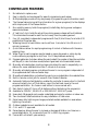
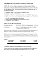
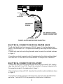
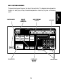
RME
USER MANUAL
FOR SE AND SE-T SERIES
CONTROLLERS
Document No. 500038 rev C
THIS PAGE INTENTIONALLY LEFT BLANK.
TABLE OF CONTENTS
Introduction ...................................................................................................1
Controller Features .........................................................................................2
MOUNTING AND INSTALLATION ..................................................................5
Mounting The Controller .........................................................................5
Controller Connections – Utility Power ....................................................5
Controller Connections – Valves And Field Wiring...................................7
Sensor Wiring ...........................................................................................7
Tapping Wires to Locate Valves in the Field ..............................................8
Electrical Specifications .............................................................................8
Electrical Connection For Master Valve.....................................................9
Electrical Connection For Pump ...............................................................9
Remote Control Capability .......................................................................9
Grounding of Controller.........................................................................10
Power Outages ........................................................................................10
KEY OPERATIONS .......................................................................................11
Function Keys .........................................................................................12
Execute Keys ...........................................................................................13
Data Keys................................................................................................13
# 1 Key Toggle ON/OFF...................................................................13
WORDS AND TERMS USED IN THE DISPLAY ............................................15
AUTOMATIC MODE......................................................................................17
RAIN MODE............................................................................................18
Programmable Rain.................................................................................18
QUICK AND BASIC PROGRAMMING.........................................................19
Set Time..................................................................................................19
Program ..................................................................................................19
Program Selection ...................................................................................19
Program Clear.........................................................................................20
Watering Day Selections..........................................................................20
Water Days .............................................................................................20
Skip Days................................................................................................21
Stations and Watering Times...................................................................21
Stations ...................................................................................................22
Quick Stations ........................................................................................23
Percentage Water Budgeting....................................................................23
Start Times..............................................................................................25
Review Programming ..............................................................................26
MANUALLY ACTIVATED FUNCTIONS WITH EXAMPLES..............................27
Manual Program .....................................................................................27
Manual Station .......................................................................................27
Manual Master Valve/Pump ....................................................................28
Manual System Check/Syringe Cycle ......................................................28
Fault Detection .......................................................................................29
Clearing Faults ........................................................................................29
ADVANCED SETUP PROGRAMMING..........................................................31
Master Valve/Pump .................................................................................31
Stack Or No Stack ..................................................................................32
Delay..................................................................................................... 32
Security Code..........................................................................................33
Sensor..................................................................................................... 34
Alarm..................................................................................................... 35
TROUBLESHOOTING ...................................................................................37
Warranty .................................................................................................38
Service.....................................................................................................38
Congratulations… you have chosen one of the most advanced irrigation
controllers available. Rain Master has taken great pride and patience in
developing and building the most trouble-free controllers in the irrigation
industry. Your new RME SENTAR controller will give you years of troublefree service, while enhancing the appearance of your landscape through
efficient control of water and energy.
To take full advantage of the many features available in your SENTAR
controller, please take a few minutes and read through your User Manual.
For those who do not have the time, a Quick Reference sheet is provided.
This sheet will allow you to perform many of the basic functions required
in programming and operating your controller.
1
CONTROLLER FEATURES
1.
2.
3.
4.
5.
6.
7.
8.
9.
10.
11.
12.
13.
14.
15.
16.
17.
18.
19.
20.
21.
22.
23.
24.
25.
No batteries to replace, ever.
Easy to identify and use keypad for ease of programming and review.
Multiple displays provide a truly simple way of programming and information recall.
The Review feature brings all the information for a given program(s) to the displays
with simple push of the Review Button.
Non-volatile memory holds the program(s) indefinitely during power outages or
seasonal shutdown.
A "real time" clock holds the actual time during power outages without batteries.
This eliminates the need to reset the clock every time the power goes out.
Four (4) completely independent programs with five (5) start times, for a total of 20
possible start times per day.
Watering time(s) for each station can be set from 1 minute to 9 hrs 59 mins in 1
minute increments.
Quick Stations allow for rapid programming of a block of stations with the same
watering time.
Water Days for each program may be based on seven day week or a skip-by-day
routine allowing a program to skip from 1 to 30 days between watering.
Programmable rain shut down allows the user to select the number of days the controller
will stay off (in rain shut down mode) before it goes back into the automatic mode.
Manually activated system check/syringe cycle allows the user to sequentially run
stations for a user selectable time from 1 minute to 9 minutes.
Manually activated program cycle allows the user to run a program independent of
its programmed start time and water days.
Manually activated station cycle allows the user to run a single station for a selected time.
Built-in remote control jack for use with Rain Master Remotes.
Automatic field wire fault detection enables the controller to sense a short in the field
wire and instantly turn off that station, report the fault and move to the next
programmed station. No fuses or reset button to be concerned with.
Rain Switch (auto-off) turns off all stations without disturbing the program(s).
Available for 120VAC, 50/60 HZ or 220/240 VAC 50/60 HZ power.
Heavy duty 18-gauge jet coat, powder coated steel enclosure for outdoor or indoor use.
Two convenient sized enclosures for easy installation of field wires.
Extra heavy duty lightning and surge protected models available for areas where
lightning is a concern.
Outdoor pedestal mount available for all models.
C-UL and FCC approved.
Percentage key allows the user to increase or decrease all station run times on a
percentage basis in 1% increments from 0% to 300% by program.
Comes with a limited 5 year warranty.
2
USER PROGARAMMABLE FEATURES
The following features can be easily selected or reconfigured by a single
push of a button (SETUP key)
• Programmable Master Valve/Pump allows the user to program
a Master Valve or Pump to go on by program.
• Programmable stacking or no stacking of programs allows the
user to have programs run one after the other (Stack Mode) or
at the same time (No Stack Mode).
• Programmable timer delay between station allows the user to
program a time delay from 1 second to 256 seconds (4 minutes
16 seconds) to allow slow-closing valves to completely shut off.
• Programmable security code allows the user to enter a 1 - 4 digit
number as a security code which will prevent entry by unauthorized
personnel.
• Programmable sensor allows the user to have a sensor device
enabled or disabled for each program.
• Programmable alarm allows the user to either enable or disable
an audible alarm in the event of a field wire fault detection.
3
THIS PAGE INTENTIONALLY LEFT BLANK.
4
CONTROLLER PLACEMENT
WARNING: Do not drill holes in the controller's case. It has all the holes necessary
for mounting it on a wall or pedestal. Drilling holes in the unit will cause metal
chips to mix with the electronics and this will cause the unit to malfunction. If, for
some reason, it is absolutely necessary to drill additional holes in the unit, carefully
remove all the electronics prior to doing so.
Controllers are suitable for indoor/outdoor environment. It is lockable, dust-free and rain
resistant. Outdoors the controller should be placed in a shaded and dry environment not
subject to direct sprinkler spray or continuous heavy moisture. Additionally, a pedestal
(PED 1) is available for outdoor controllers; contact your Rain Master distributor.
MOUNTING THE CONTROLLER
1. On an upright, flat and secure surface, place the mounting bracket at eye level and
fasten securely.
2. Mate the bracket on the back of the controller to the mounted bracket and hang the
controller.
3. Secure the bottom of the controller by placing a screw through the hole located in its
back wall at bottom center.
CONTROLLER CONNECTIONS – UTILITY POWER
1. Refer to Figure 1 - Power and Field Wiring.
2. Mount controller.
3. Place Rain Switch in Off position.
4. Remove lower panel.
5. Using #10-gauge or heavier copper wire, connect ground screw to ground rod or
grounded water pipe using a ground rod clamp. The wire should be as short as possible
with no sharp bends or kinks. If multiple clocks are being installed in the same location,
use a ground rod for each and contact the factory for the RMIS pamphlet on proper
grounding techniques.
6. Thread condulet onto transformer.
7. Connect supply line grounded conduit to condulet.
8. Connect 120v, 50/60Hz supply line to transformer wires within the condulet
Install gasket and cover onto condulet with 2 screws.
9. Follow all appropriate electrical wiring codes.
10. Replace the lower panel and place the Rain Switch in Auto position after field valve
wiring is complete.
5
MOUNTING &
INSTALLATION
MOUNTING AND INSTALLATION
YELLOW
YELLOW
WHITE
TO VALVE
COMMON
BLACK
TO MASTER
VALVE/PUMP
GROUND
TRANSFORMER
#10 (or heavier)
GROUND WIRE
CONDULET
GREEN
BLACK
8' END
ROD
WHITE
TO AC POWER
SOURCE
NOTE: IF THE TRANSFORMER
HAS A GROUND WIRE (GREEN),
THEN CONNECT AS SHOWN.
FIGURE 1. POWER AND FIELD WIRING
6
CONTROLLER CONNECTIONS – VALVES AND FIELD WIRING
The controller utilizes quick disconnects and color coded wires. The wires are 24" long
and each end must be stripped and attached to the corresponding field wire. Unused wires
should be taped off to prevent shorting. SENTAR models SE-B, SE-SB, SE-T and SEST, come equipped with terminals to which field wires are directly connected and also
include an expanded size field wiring cavity.
The station numbers are labeled just above the quick disconnects behind the lower panel
of the controller. Simply match the station's wire to the appropriate field wire. Note that
the controller's COMMON wire is WHITE and the MASTER VALVE/PUMP is BLACK.
Should it be necessary to detach the Quick Disconnect blocks from the printed circuit
board, grab the plastic assembly and pull down gently but firmly.
Note: When reattaching the Quick Disconnect, be careful to make sure that the lip at
the top of the plastic connector is facing you as you push the connector onto the pins.
Additionally, be sure to match the Quick Disconnect blocks with the
corresponding
color as labeled on the bottom of the printed circuit board.
2 WIRE SENSOR
3 WIRE SENSOR
24 VAC
COMMON
VALVE
COMMON
FIGURE 2. SENSOR WIRING
SENSOR WIRING
Most sensors, either Rain or Moisture type, are generally 2 or 3 wire.
The 2 wire sensors are connected to terminal 1 and 2 on the sensor terminal block (See
Figure 2)
Most 3 wire sensors will work if connected as follows: (See Figure 2)
Common wire to terminal #2
Valve common connects to terminal #1
24 VAC wire connects to terminal #3
Please check sensor wiring instructions for further details.
7
TAPPING WIRES TO LOCATE VALVES IN THE FIELD
DON'T – Do not turn a station on and tap a wire to the controller's station
terminal/wire to see what valve in the field is connected to it. This is damaging to
both mechanical and solid state controllers and will cause the controller to go into a field
wire fault detection mode. The simple method shown below is safe and will work for
both types of controllers.
1.
2.
3.
4.
5.
Use Manual Station to turn on Station 1, perhaps for 1 hour.
Flip the Rain Switch to the Off position.
Touch the wire from the unknown field valve to the controller's Station 1 terminal/wire.
Flip the Rain Switch to the Auto position and the valve on that wire will be activated.
When you know what valve it is, flip the Rain Switch off before removing the field
wire from the controller's station terminal/wire.
6. Choose the next field wire and start the process over at Step 2.
7. When all done, turn off Station 1.
ELECTRICAL SPECIFICATIONS
Input power required :
105-130 VAC, .50/60 Hz, .5 amp maximum, .1 Amp idle
Output power:
24 VAC, 1.5 Amps maximum total output, or 36 VA
1 Amp per station or Master Valve
Solenoids are rated in either Amps or VA. The term VA stands for Volt-Amps, which is
obtained by multiplying the Amps required by the operating voltage, 24 VAC.
Most modern solenoids require approximately .25 Amps, which is equivalent to 6 VA.
This means that up to six solenoids can be energized at the same time. If you are using a
Master Valve, you may use the NO STACK option in SETUP and run all four programs
simutaneously.
Example:
Four programs
Master Valve
(.25 A times 4)
(.25 A times 1)
Total Current
1.00 Amps
.25 Amps
1.25 Amps
This does not exceed the maximum allowable 1.5 Amp controller limit.
If higher current solenoids are used or if more than one solenoid is connected to one
station output, caution should be used when operating in NO STACK mode.
8
YELLOW
BLACK
YELLOW
TO
TRANSFORMER
WHITE
1
RAIN MASTER PART
NO. RLY1 OR
EQUIVALENT.
3
24 VAC
COIL
4
2
NOTE: MOUNT RLY1 IN LOCKED
NEMA 3R ELECTRICAL ENCLOSURE.
OBSERVE ALL ELECTRICAL CODES.
TO PUMP OR
PUMP START RELAY
FIGURE 3. MASTER VALVE OR PUMP CONNECTION
ELECTRICAL CONNECTIONS FOR A MASTER VALVE
The Master Valve/Pump line is a source of 24 VAC power. It is active whenever any
station in the controller is on. It may also be activated by itself using the Manual Station
function.
If there is only one clock controlling the master valve, then wire the controller as shown
in Figure 1.
If more than one clock is going to control the master valve, the clocks must be isolated
from each other. Contact RMIS for documentation on multiple clock installations.
ELECTRICAL CONNECTION FOR A PUMP
If there is only one clock controlling the pump and if the pump has a 24 VAC starting
relay, then wire the MV and COM lines of the controller to the pump's relay similar to
the connections made for the master valve in Figure 1.
If the pump does not have a 24 VAC relay, then the controller must be isolated as is shown
in Figure 3.
If more than one clock is going to control the pump, the clocks must be isolated from
each other. Contract RMIS for the pamphlet on multiple clock installations.
9
REMOTE CONTROL CAPABILITY
All Rain Master controllers feature patented built-in remote control capability which
allows the user to operate the controller via a Rain Master hand held transmitter. (Consult
the Remote Manual for operating instructions). Never connect anything but a Rain Master
remote control receiver to the controllers front panel remote control connector or damage
will result.
Connecting to any other remote control device to any portion of the Rain Master controller
will void all warranties and may cause damage.
GROUNDING FOR SENTAR MODEL SE-T
The SENTAR model SE-T was developed to protect the controller against lightning and
line surges.
In areas where lightning and line surges are common, it is strongly recommended to use
the SENTAR model SE-T, provided the controller is properly grounded.
Grounding Instructions
1. Mount the controller as close as possible to the grounding rod, so that the #10 grounding
wire from the controller to the ground rod is as short as possible. Ensure the grounding
wire is free of nicks and bends.
2. Use a grounding rod clamp to secure grounding wire to grounding rod. Be sure all
surfaces are clean of oxides and dirt, and that all connections are solid and secure.
3. In areas of very dry soil or sand, it may be necessary to "Dope" the grounding rod.
Contact your Rain Master distributor or Rain Master for Grounding Pamphlet
RMIS Grounding.
4. Should the 8' grounding rod not penetrate completely into the soil it is acceptable to
put it into the ground on a slight angle. It is important that the rod be a full 8' into
the ground, with only enough of the rod showing to clamp the wire on. Should other
grounding installation requirements be necessary, contact your distributor or Rain Master.
Note: It is important to check the resistance periodically to ensure it is not greater than
10 ohms. Contact your Rain Master Distributor for details.
POWER OUTAGES
Your RME SENTAR controller has been designed with non-volatile memory
which means that all program and setup information will be maintained indefinitely
in the event the 120 VAC line power is lost.
In addition to the non-volatile memory, specialized circuitry maintains the time
during outages without the use of batteries. When power is restored, the controller
intelligently restarts any programs at the appropriate station number.
Note: If power remains off continuously for approximately 1 month or longer, the
time will be lost and the time display will flash.
10
KEY OPERATIONS
There are three types of keys on the face of the controller. The diagram below shows the
location of each group of keys. A detailed explanation of each key is given on following
pages.
REMOTE
CONTROL
CONNECTOR
DAYS/STATIONS
DISPLAY
DATA KEYS
KEY
OPERATIONS
FUNCTION KEYS
DAYS
S M T W T F S
STATIONS MV 1 2 3 4 5 6 7 8 9 10 11 12 13 14 15 16 17 18
REMOTE
CONTROL
19 20 21 22 23 24 25 26 27 28 29 30 31 32 33 34 35 36
SET TIME PROGRAM
START
TIMES
WATER
DAYS
QUICK WATER %
STATIONS BUDGET
888888888
STATIONS
REVIEW
PROGRAM
SUN
MON
WED
THU
1
4
RAIN SWITCH
SAT
7
AUTOMATIC WATERING
SETUP
RAIN SWITCH
N O WAT E R I N G
MANUAL
SKIP DAYS
CONTROLLER
MESSAGE
DISPLAY
11
QUIT
CLEAR
AM
PM
2
TUE
3
FRI
5
6
8
9
0
ENTER
EXECUTE KEYS
FUNCTION KEYS
These keys (dark tan color) perform a specific function.
SETUP
Allows the user to perform the following set-ups:
- Program a Master Valve/Pump to any
or all programs
- Program stacking or non-stacking of
programs
- Program time delay between station(s)
from 0 - 255 seconds (4 mins. 16 secs.)
- Program a security code
- Program a sensor to any or all programs
- Program audible alarm warning
SET TIME
Allows the user to set the current time and day in the controller.
PROGRAM
Allows the user to select the program that is required (from 1 - 4).
WATER
DAYS
Is used to select the water days that the program is to operate on.
STATIONS
Is used to select the stations and run times in each program.
START
TIMES
Is used to select the start time(s) for each program. (5 per program).
QUICK
STATIONS
Is used when a block of stations with the same run time is being
programmed.
WATER %
BUDGET
Is used to allow the user to change the run times (from 0% to
300%) for each station on a percentage basis by program
REVIEW
Is used to review all the information on each program in the
controller.
MANUAL
SKIP DAYS
Is used to allow the user to turn on a program, station, or check
all stations. Additional uses include locking and unlocking the
controller once a security access code has been entered via SETUP,
and advancing to the next station when executing a program.
Is used when the user wishes to use the Skip By Day method.
12
EXECUTE KEYS
These keys (light tan color) will execute the function that has been selected to be
programmed.
ENTER
All DATA KEY input (see below) must be followed by the
ENTER key to be accepted by the controller.
CLEAR
Allows the user to clear a selected function out of a program.
This key will also put the controller in the programmable rain mode.
QUIT
Is used on completion of a function after it has been executed
and will return the controller to the automatic mode.
This key may be pressed to exit any function.
DATA KEYS
These keys ( dark blue color) are used to select days of the week when entering time and
day, and are used to select numbers such as run times, delay times etc.
The number 1 key is also a toggle ON/OFF key when used in the Setup mode.
SUN
MON
WED
THU
1
4
SAT
7
AM
PM
2
TUE
3
FRI
5
6
8
9
0
13
THIS PAGE INTENTIONALLY LEFT BLANK.
14
WORDS AND TERMS USED IN THE DISPLAY
HELLO
=
PROGRAM
Hello will be displayed when the controller is powered
up, for the very first time.
When Hello is displayed there are NO user programs
in the controller. If left in the HELLO mode the
controller will begin to water every station for 10
minutes, starting 6 hours after the HELLO has been
displayed.
Hitting any key exits HELLO mode, and removes
the default watering program.
MV/P
=
Master Valve or Pump
=
Run programs one after another
=
Run programs at the same time
=
Time delay between stations (in seconds)
=
Access or Security Code
=
Sensor input
=
An audible beep will be given off (or not) if a fault
is detected.
PROGRAM
STACK
PROGRAM
N O STACK
PROGRAM
D ELAY000
PROGRAM
C O DE0000
PROGRAM
SNSR
PROGRAM
A LARM ON/OFF
PROGRAM
15
WORDS &
TERMS
UNDER SETUP
OTHER TERMS
LOCKED
=
A security code has been entered and enabled. Requires
re-entry of the access code to unlock.
=
Low, used in quick stations function
=
High, used in quick stations functions
=
Inhibited, used with the rain switch
=
Length, used in station function
=
Left, used in skip days function
=
No, used anytime to indicate invalid info.
=
Off, indicates the controller is off and will not water
=
Okay, indicates an acceptance of an option
=
Sorry, indicates invalid information that cannot be
accepted
=
Program or station used in manual function
=
Program, used in program function
=
Percentage, used in percentage function
=
Skip days, used in the skip days function
=
Set time, used in the set time function
PROGRAM
LOPROGRAM
HIPROGRAM
I
PROGRAM
LN
PROGRAM
LFT
PROGRAM
NO
PROGRAM
OFF
PROGRAM
OK
PROGRAM
SORRY
PROGRAM
P OR S
PROGRAM
PROG
PROGRAM
P TPROGRAM
SDPROGRAM
SET TIME
PROGRAM
16
STATION
=
Station, used in the stations function
=
Stations, used in the review feature
=
Water days, used in the water days function
=
The controller has been placed in the programmable
rain mode and will not water for “N” days. “N”
indicates the remaining days (1-7) before next water.
=
The rain sensor associated with this program is in a
wet condition, used in the review feature.
=
The rain sensor associated with this program is reading
a dry condition.
=
A program is running in the automatic mode
but no stations are watering because the rain
sensor is enabled and a wet condition exists.
=
An overcurrent or short circuit has occured on one or
more stations, field wires, or valve solenoids. Press
Review to display the faulty stations.
PROGRAM
S STATIONS
PROGRAM
WDAY
PROGRAM
RAIN-N
PROGRAM
SNSR-WET
PROGRAM
SNSR-DRY
PROGRAM
PROGRAM
F A U LT … P R E S S …
REVIEW
PROGRAM
AUTOMATIC MODE
The controller is in the Automatic Mode whenever the time is displayed, and the day of
the week indicator light is lit.
Pressing
QUIT
will always return the controller to the automatic mode.
When a program is watering in the Automatic Mode, the station and program number
will be displayed as a convenience.
A
in place of the program number indicates a program is running but all stations are
off because the rain sensor is enabled and a wet condition exists.
17
To advance to the next station in a program when a program is already watering,
Press:
MANUAL
To stop and cancel a program that is watering,
Press:
CLEAR
QUIT
The controller goes back to the Automatic Mode.
RAIN MODE
The controller has a Rain Switch. The switch MUST BE in the "Auto Watering" position
anytime watering is desired. In the "Auto Watering" position, watering WILL occur if
the controller is programmed to do so.
The switch should be placed in the "No Watering" position when no watering is desired,
such as when it is raining, etc. In the "No Watering" position, no watering will occur and
the letter "I" will appear in the display to indicate that all programs are Inhibited from
watering. The user's program will not be disturbed.
PROGRAMMABLE RAIN
This method is used in place of the Rain Switch when you know how many days you want
the controller to stay off. It allows you to select the number of days, from 1-7, that the
controller will stay in the Rain Mode after which it will go back to the Automatic Mode
by itself.
EXAMPLE: You wish the controller to stay off for 6 days.
Press: CLEAR
FRI
6
ENTER
The controller will display
RAIN-6
PROGRAM
Each night at midnight the controller will deduct one day until it finally goes back to the
Automatic Mode.
Note: no watering will occur when it goes back to the Automatic Mode if you have also
placed the Rain Switch in the “No Watering” position.
18
QUICK AND BASIC PROGRAMMING
Before the controller will operate, some basic information must be programmed.
1. Set the Time of day and Day of the week for the controller.
2. Establish a valid watering program:
a. Choose the program number you wish to work with (1-4).
b. Set the water days
c. Set the stations and the watering time for each station.
d. Set the start time(s) the program will begin to water on the chosen days.
SET TIME
This is used to set the current time of day and the current day of the week.
EXAMPLE 1: The time is 2:00 PM, Sat.
Press:
SET TIME
MON
2
0
0
AM
PM
ENTER
SAT
7
ENTER
The controller goes back to the Automatic Mode.
EXAMPLE 2: The time is 10:35 AM, Tue.
SET TIME
SUN
1
0
TUE
3
THU
5
ENTER
TUE
3
ENTER
The controller goes back to the Automatic Mode.
PROGRAM
This is used to select the program(s) you wish to work with. Once selected, you need
not change the Program # until you wish to program or review information in a different
program. There are 4 programs available for your use. They are referred to as 1, 2, 3,
and 4. If desired, it is also possible to select and clear ALL information in a program
using this function.
PROGRAM SELECTION
To select the program you wish to work with, either 1, 2, 3, or 4. While programming
other functions, the selected program number is displayed as a convenience.
EXAMPLE: You wish to work with Program 2.
Press:
PROGRAM
MON
2
ENTER
The controller goes back to the Automatic Mode.
19
QUICK & BASIC
PROGRAMMING
Press:
PROGRAM CLEAR
If desired, it is possible to both select and clear all information in a program.
EXAMPLE: You wish to select and clear all information in Program 1.
Press:
PROGRAM
SUN
1
CLEAR
The controller goes back to the Automatic Mode
WATERING DAY SELECTIONS
Watering days for Programs 1, 2, 3 and 4, may be set on a 7 day week OR a skip days
mode. Although you cannot do both within the same program, each program may be
set to either mode.
EXAMPLE: Program 1 may be on a 7 day weekly basis but Program 2 might be on a
skip days basis.
WATER DAYS
To select watering days based on a 7 day week. Watering will occur on the days selected
each and every week. Selected days are shown in the top display. The Program # is shown
in the display as a convenience.
EXAMPLE: You wish to water on Sunday, Wednesday and Friday.
Press:
WATER
DAYS
SUN
1
ENTER
WED
4
ENTER
The controller goes back to the Automatic Mode.
To clear a watering day, such as Sunday,
Press:
WATER
DAYS
Press:
QUIT
SUN
1
CLEAR
when done,
The controller goes back to the Automatic Mode
To review Water Days information,
Press:
WATER
DAYS
Press:
QUIT
(An LED light will light up for every
day that watering is to occur.)
when done,
The controller goes back to the Automatic Mode.
20
FRI
6
ENTER
QUIT
SKIP DAYS
This is used to establish a number of days between watering, from 1 to 30, and how many
days are left till the first watering will begin. If information has been entered in the past,
the Skip Day number will be shown in the display. The Program # is shown in the display
as a convenience.
Note: 0 days left means the watering day is today.
Note: By using the skip days mode you can have a program water every 2nd, 3rd, 4th,
... or 30th day as may be desired.
EXAMPLE: You wish to skip 2 days and water every third day, and to start it 4 days from now.
Press:
SKIP DAYS
MON
2
ENTER
WED
4
ENTER
The controller goes back to the automatic mode.
To clear all Skip Days information,
Press:
SKIP DAYS
CLEAR
QUIT
the controller goes back to the Automatic Mode.
To review Skip Days information
Press:
SKIP DAYS
and the skip day number is shown,
Press:
ENTER
Press:
QUIT
(the number of days left before
the next watering is shown.)
when done,
The controller goes back to the Automatic Mode.
STATIONS AND WATERING TIMES
Any stations may be placed in any program. Stations may be placed in more than one
program at a time if desired. Within each program, each station can have a different run
time. The watering time for each station may be set from 1 min to 9 hrs and 59 mins.,
in increments as small as 1 min. Additionally, there are two ways of placing stations and
watering times in a program.
The first method is a station and its watering time entered together. The second method
allows you to rapidly program a block of stations all with the same watering time.
21
STATIONS
This is used to select the stations and set the length of watering for each station. After
entering the desired Station #, the watering length for the station is then entered. Percentage
is briefly shown at the beginning to remind you of its setting. Selected stations are shown
in the top display. The Program # is shown in the display as a convenience.
EXAMPLE: You wish to set Station 1 for 10 mins., Station 2 for 10 mins, Station 6 for
1 hr. and 15 mins. and Station 7 for 8 mins.
Press:
STATIONS
SUN
1
MON
ENTER
2
ENTER
FRI
ENTER
6
SAT
7
ENTER
SUN
0
ENTER
1
0
ENTER
SUN
SUN
1
SUN
1
8
1
THU
5
ENTER
ENTER
when done,
Press:
QUIT
The controller goes back to the Automatic Mode.
To clear a station and its watering time, such as Station 7,
Press:
STATIONS
Press:
QUIT
SAT
7
CLEAR
when done
The controller goes back to the Automatic Mode.
To review selected Stations information
Press:
STATIONS
Press:
QUIT
(An LED light will light up for every
station that has a valid run time).
when done,
The controller goes back to the Automatic Mode.
To review the watering time of a station, such as Station 6,
Press:
STATIONS
Press:
ENTER
FRI
6
ENTER
(the watering length is displayed)
to leave the watering time as is and continue
reviewing
22
when done,
Press:
QUIT
The controller goes back to the Automatic Mode.
QUICK STATIONS
This is used to rapidly program a block of stations which all have the same watering length.
First the lowest station number is entered, then the highest and then the watering length.
This length is applied to all the stations from the lowest through the highest. Selected
stations are shown in the top display. The Program # is shown in the display as a
convenience.
EXAMPLE: You wish to set all stations from 12 through 34 for 56 mins.
QUICK
Press: STATIONS
SUN
1
MON
2
ENTER
TUE
3
WED
4
ENTER
THU
5
FRI
6
ENTER
The controller goes back to the Automatic Mode.
PERCENTAGE
The Percentage function provides for simple water budgeting by providing an easy method
of increasing/decreasing the watering lengths of ALL stations in a program with one simple
entry. It is particularly useful during abnormally dry/hot/cold or wet periods.
The Percentage is set to 100 in all four programs by default, therefore, unless changed,
each station in a program will run for 100% of its programmed time. Percentage may
be set from 0 to 300%, in increments as small as 1%, for Programs 1, 2, 3 and 4
independently.
For instance, setting the Percentage in a program to 161 will make the watering length
of each station 1.61 times its programmed watering length. Setting the Percentage to 70
will make the watering length 0.70 times its programmed watering length.
Note: Even if Percentage is set to other than 100, the watering lengths of all stations in
a program will not be changed when you view them. At all times, the length shown is
the originally programmed length corresponding to 100%. However, the watering length
will be modified when the station waters.
EXAMPLE: You wish to set a Percentage of 110 which will increase the watering times
of all stations in a program by 10%.
Press:
WATER %
BUDGET
SUN
1
SUN
1
0
ENTER
The controller goes back to the Automatic Mode.
23
To clear Percentage
Press:
WATER %
BUDGET
CLEAR
QUIT
The Percentage is reset to 100 and the controller goes back to the Automatic Mode.
To review Percentage
Press:
WATER %
BUDGET
Press:
QUIT
when done,
The controller goes back to the Automatic Mode.
START TIMES AND AUTOMATIC PROGRAM
OVERLAP PROTECTION
There are five start times available for each of Programs 1, 2, 3 and 4. They are referred
to as Start Time 1 – Start Time 5.
Additionally, the controller allows the user to select (via Setup) whether programs will be
allowed to run one at a time (Stack) or run concurrently (No Stack) in the event that start
times overlap with one another. Using Stack operation the controller ensures that only
one program (e.g. one station) is allowed to be turned on at one time regardless of
conflicting start times. The controller program(s) will wait for completion of the currently
executing program before it will start the next program.
EXAMPLE 1: If Program 1 is one hour long, due to the stations and watering times placed
in it, and you set three of its start times to 7:00 AM, the program will water three times
- from 7:00 to 8:00, 8:00 to 9:00 and 9:00 to 10:00 thereby providing two repeat cycles.
EXAMPLE 2: If Program 1 was again one hour long and was set to start at 7:00 AM
Mon., and Program 3 was set to start at 7:30 AM on Mon. and Tue., then on Mon.
Program 3 would begin at 8:00 AM, when Program 1 ended, but on Tue. it would begin
at 7:30 AM.
The Stack operation ensures that you will always get the number of watering cycles you
desire and at the same time your system will never be under-pressurized because two
programs are running simultaneously.
Note: The controller is shipped with Stack active, however, it may be programmed so
that multiple programs can be run simultaneously. See Setup.
24
START TIMES
This is used to set the start time for a program. The Program # is shown in the display
as a convenience.
EXAMPLE: You wish the program to start watering at 7:10 AM and 4:30 PM
Press:
START
TIMES
SAT
SUN
WED
TUE
7
4
1
3
AM
0
PM
when done,
Press:
QUIT
The controller goes back to the Automatic Mode.
To review Start Times
Press:
START
TIMES
(Start Time 1 is displayed).
To review Start Time 2
Press:
ENTER
Press:
QUIT
When done
The clock goes back to the Automatic Mode.
To clear a start time, such as Start Time 2
Press:
START
TIMES
(Start Time 1 is displayed).
To get to Start Time 2
Press:
ENTER
(Start Time 2 is displayed.)
To clear it
Press:
CLEAR
(The controller goes
to Start Time 2.)
ENTER
0
QUIT
The clock goes back to the Automatic Mode.
25
ENTER
(The controller goes
to Start Time 3.)
REVIEWING PROGRAMS
A unique feature of the SENTAR controller is its REVIEW feature. At the push of a
button, all program information will be displayed. Successive pushes of the REVIEW
key cause the information to advance. Another way of reviewing information is to press
and hold the Review key. As the key is held the information will automatically advance
at a readable rate. Removing your finger from the button causes the scrolling information
to stop.
Information in Program 1 will be displayed first, followed by Program 2, 3 and 4.
The information presented is as follows:
1. If the Rain Sensor has been Enabled via Setup for this program then:
SNSR-WET or SNSR-DRY will be displayed.
2. Start Times 1, 2, 3, 4 and 5 (displayed as Start Times).
3. Water Days (displayed as W DAY)
4. Skip Days (displayed as SD) and the number of days left until the next watering
(displayed as LFT)
5. Percentage (displayed as PT)
6. Stations and their watering times (displayed as STATIONS)
7. The total watering time for the program (displayed with H [hrs] and M [minutes])
Note: The watering length shown for each station is the programmed length and will not
be changed by the value you may have set for the percentage adjust functions.
when done,
Press:
QUIT
The controller goes back to the Automatic Mode
EXAMPLE: You wish to review program 3 only
Press:
PROGRAM
Press:
REVIEW
Press:
QUIT
TUE
3
ENTER
when done,
The controller goes back to the Automatic mode.
26
MANUALLY ACTIVATED FUNCTIONS WITH EXAMPLES
The Manual Mode offers four different features shown below:
MANUAL PROGRAM
This is used to run a program - assuming stations are in the program.
EXAMPLE: You wish to run Program 1.
Press:
MANUAL
PROGRAM
SUN
1
ENTER
(The display shows a 1 to indicate
Program 1 is running. The active
stations are also displayed.)
The controller goes back to the Automatic Mode.
To advance to the next station when the program is already watering:
Press:
MANUAL
To stop the watering program that is currently running:
Press: CLEAR
QUIT
The controller goes back to the Automatic Mode.
MANUAL STATION
This is used to run a selected station for a selected time.
Press:
MANUAL
STATIONS
FRI
6
ENTER
MON
2
THU
5
ENTER
(The display shows station and watering time. As time elapses, watering time will count
down. When time ends, the station shuts off. The controller goes back to the Automatic
Mode.)
To stop the watering station
Press:
QUIT
The controller goes back to the Automatic Mode.
27
MANUAL
FUNCTIONS
EXAMPLE: You wish to water station 6 for 25 min.
MANUAL MASTER VALVE/PUMP
This is used to run only the Master Valve or Pump for a selected time. The MV/P is
designated as Station 0.
EXAMPLE: You wish to run your pump or open the master valve for 4 min.
Press:
MANUAL
STATIONS
0
ENTER
WED
4
ENTER
To stop:
Press:
QUIT
MANUAL SYSTEM CHECK/SYRINGE CYCLE
As a convenience for "walk throughs" and service work, the controller has a system check
feature built in. This will run each station, from the first to the last, for a selectable time
of 1 to 9 mins.
EXAMPLE: For a 3 min. System Check
Press:
MANUAL
TUE
3
DO NOT PRESS ENTER
CHECK will appear in the display indicating Check Mode. When the last station has
watered, the controller goes back to the Automatic Mode.
To advance one station at a time:
Press:
MANUAL
To stop this cycle,
Press:
CLEAR
QUIT
The controller goes back to the Automatic Mode.
Caution: This mode sequentially runs every station in the controller. For example
you have a 24 station unit but only use 23 stations, it will still apply power for Station
24 and while doing so will apply power to the Master Valve/Pump terminal.
This could be a problem for a system using a pump because during the period that Station
24 is activated, the pump will be pumping against a closed system. If the system uses a
master valve, it will be activated during the period that Station 24 is active and this could
cause heating of the master valve's solenoid (if the valve depends on water flow to cool
it). Therefore, if all stations are not used, cancel the System Check/Syringe cycle after the
last used station has watered.
28
FAULT DETECTION
The SENTAR controller has been equipped with automatic detection of station wiring
short circuits which may occur due to improper field wiring or faulty valve solenoids.
In the event that a station draws excessive current, the following action will occur:
1. The offending station will be immediately turned off.
2. The next scheduled station of the program will be started.
3. The display will alternate with the following words:
FAULT . . . . . . . PRESS . . . . . . . REVIEW
4. The controller shall chirp once every six seconds signifying the fault condition.
Note: "chirping or alarm" may be disabled via the Setup key.
5. The controller will continue to execute programs, however, any faulted station(s)
will not be turned on again.
Note: If multiple stations are on simultaneously, and the controller detects an overcurrent
fault, all running stations will be diagnosed as faulty.
CLEARING FAULTS
When the controller has detected station fault(s) the user should press the Review key to
determine where the fault(s) have occurred.
When the Review key is pressed the following shall occur:
1. The display shall now show FAULT (alternating display stops) while station lights
illuminate to show which station(s) short circuits have occurred. The audible
chirp will also be suspended.
2. At this point the fault(s) can be cleared by pressing Clear. Once cleared, all faulted
stations will be energized on the next watering cycle and the audible chirp shall not
resume. The controller shall return to the automatic mode.
29
THIS PAGE INTENTIONALLY LEFT BLANK.
30
ADVANCED SETUP PROGRAMMING
In addition to the many operating features available in your SENTAR controller, there are
a number of programmable features available. (See User Programmable Features on page 3.)
Setup Options and Controller Defaults
Function
Option
Default
Master Valve Used
Uses, Does Not Use
1,2,3,4 (all programs enabled)
Stack (Overlap Protection)
On, Off
On
Delay (Station Delay Time)
0-255 seconds
000 (feature disabled)
Code (Security Code)
None
0000 (feature disabled)
Sensor Used
Uses, Does Not Use
(all programs disabled)
Alarm
On, Off
On
By simply pushing the Setup key, you can program the following functions. Successive
pushing of the Setup key will allow you to advance to the next setup feature.
MASTER VALVE/PUMP (MV/P)
Using this feature allows you to program a master valve or pump to be activated when
program 1, 2, 3, or 4 is activated.
EXAMPLE: You want a pump to go on when Programs 1 and 3 are running.
Press:
you will see
SETUP
MV/P1234
PROGRAM
Press:
MON
2
WED
4
removes Programs 2 and 4 from having the Master Valve or
Pump activated when these two programs come on.
you will see
MV/P1 3
Press:
ENTER
Subsequent pressing of 2 and 4 will add the pump
activation feature back into Programs 2 and 4.
31
ADVANCED
SETUP
PROGRAM
STACK or NO STACK
This feature allows you to run your programs one after another (Stack) or at the same
time (No Stack). Where volume of water and pressure will allow, you have the option
of running several stations from different programs at the same time.
Note: The maximum current draw cannot exceed 1 amp per station, and
1.5 amps for the controller.
EXAMPLE: You have a 30 station controller, and watering must be completed by 7:00AM
and cannot begin until 2:00 AM (5 hours total).
You can put:
Station 1 through 7 in Program #1
Station 8 through 14 in Program #2
Station 15 through 21 in Program #3
Station 22 through 30 in Program #4
Now set up your run times for each station, and the start time of 2:00AM. You must be
sure not to have any program go over the 5 hours total run time (check in review mode).
You must also ensure your system can supply the volume of water required to supply 4
stations at one time.
To activate No Stack feature:
Press:
Press:
SETUP
2 times
you will see
STACK
PROGRAM
SUN
(remember this is a toggle key when used in the
Setup mode) until you see N O S T A C K
1
PROGRAM
when done,
Press:
ENTER
QUIT
DELAY
This feature allows you to program a delay time between stations. A programmable delay
can be useful to allow stations to reach a steady state condition before energizing the next
station.
EXAMPLE: You want to have a 68 second delay time between stations being turned on
Press:
SETUP
3 times
you will see
DELAY000
PROGRAM
Press:
FRI
6
8
ENTER
you will see
DELAY068
PROGRAM
Press:
QUIT
QUIT
Note:
Screen will read seconds only up to 255 seconds.
32
SECURITY CODE
Note: This feature should only be used where security is limited.
The SENTAR controller has the capability to enter a password code which must be
entered before any function(s) can be executed. This code can be up to 4 numbers long.
Use a number that can be easily remembered, and have it written down should you forget.
Entering A New Security Code
EXAMPLE: You wish to enter the year you were born as a code 1960
Press:
SETUP
Press:
SUN
Press:
QUIT
1
4 times
you will see
FRI
ENTER
0
6
9
CODE0000
PROGRAM
Enabling Security Code
Once you have completed operating or making changes to your controller you can enable
the security code:
Press:
MANUAL
ENTER
ENTER
The controller will go back to the Automatic Mode.
Should you forget to enable the security code, the code will automatically become enabled
at midnight and no one will be allowed to operate the controller without first entering
the security code.
During the same day as you have entered the code, you can go back and change or erase
it by following the example below.
Disabling Security Code (LOCKED Controller)
Once the Security Code feature has been enabled, it will be necessary to enter the security
code every time you wish to operate or change your controller.
To disable the security code used in the example above:
Press:
MANUAL
ENTER
SUN
1
9
FRI
6
0
ENTER
Eliminating Security Code
To eliminate the Security Code completely, first disable code as described above, then:
Press:
SETUP
4 times
you will see
CODE1960
PROGRAM
Press:
0
0
0
ENTER
0
QUIT
33
SENSOR
Note: When this symbol appears in the beginning of the display screen, it
indicates that the Sensor is reading "Wet", and one or more programs that are enabled
for sensor operation have started. No stations, however, shall water due to the wet
condition.
The SENTAR Controller has the ability to affect irrigation based on an external rain
sensor or remote switch, such as a Moisture Sensor. This feature can be programmed by
individual program, so that one or more programs will cease watering as long as the rain
sensor is active.
The external sensor or switch must be of the type which is Closed when there is no rain
detected, and opens when rain is detected or it is desired to suspend irrigation. Most
commercial rain sensors are of this type. See the wiring instructions on page 7.
EXAMPLE: You have program 4 set up to operate your outdoor lighting, however you
also have a rain sensor connected to your SENTAR.
Press:
SETUP
5 times
you will see
SNSR
PROGRAM
Press:
SUN
Press:
QUIT
1
MON
2
TUE
you will see S N S R 1 2 3
ENTER
3
PROGRAM
Once programmed in the above manner, the designated program(s) will not turn on any
stations unless the rain sensor terminals labeled 1 & 2 are shorted together, either by an
external switch or the appropriate rain sensor.
The status of the rain sensor can be determined by pressing the Review key repeatedly or
holding it down until the display shows the word SNSR- followed by Wet or Dry. If Dry,
the controlled program(s) will operate normally. If Wet, no irrigation will take place on
those program(s). Additionally, when a program is scheduled to operate, an asterisk will
appear in the leftmost location in the display IF the external sensor has detected rain, or
the external switch is Open.
Note: The external sensor is independent of the Rain Switch on the front of the controller.
Leave the switch in the Automatic Watering position.
To reinstate program 4 into the Sensor Mode:
Press:
SETUP
5 times
WED
4
ENTER
you will see
SNSR1234
PROGRAM
when done,
Press:
QUIT
34
ALARM
The SENTAR controller is equipped with an audible alarm feature which notifies the
operator if a field wire fault has been detected.
To program this alarm:
Press:
SETUP
6 times
you will see
ALARMOFF
PROGRAM
Press:
SUN
1
(Toggle Key)
you will see
ALARMON
PROGRAM
Press:
ENTER
QUIT
35
THIS PAGE INTENTIONALLY LEFT BLANK.
36
TROUBLESHOOTING
Symptom
Display is blank
Action
1. Ensure controller has power and all wires are
properly connected. (page 6)
2. Check secondary voltage of transformer for
24 VAC
No stations turn on
automatically
1. Is the controller in Automatic Mode?
If No - Press
QUIT
2. Ensure the Rain Switch is in the “Auto Watering”
position.
*
3. Does appear in left most position of display?
Yes - Rain Sensor is enabled and is reading a wet
condition (see SETUP)
4. Ensure that the Master Valve wiring and
SETUP is correct (page 9, 31).
5. Activate Manual System Check (page 28)
If station turns on, review programs: (page 26)
• Water Days
• Station Runtimes
• Percentage Valid
• Start Times
Display alternates with
FAULT…PRESS…REVIEW
A problem with station field wiring has occurred
(page 29).
A station remains on
Place Rain Switch in “No Watering” position.
If station remains on then:
• Check for dirt in valve’s solenoid which will
cause the solenoid to stick
• Check for obstructions in valve, or torn
diaphragm
If station goes off then:
• Check station’s programmed watering time
• Check program percentage
Flashing Time
in Display
The time has been lost (see SET TIME page 19)
TROUBLE
SHOOTING
37
RAIN MASTER LIMITED WARRANTY
Rain Master Irrigation Systems Inc. warrants to the first customer purchaser that this Rain Master brand product
(the "product"), when shipped in its original container, will be free from defective workmanship, and materials
and agrees that it will, at its option, either repair the defect or replace the defective product or part thereof at
no charge to the purchaser for parts or labor for the time period set forth below.
This warrant does not apply to any appearance items of the product nor to any product the exterior of which
has been damaged, or defaced, which has been subjected to misuse, abnormal service or handling, or which has
been altered or modified in design or construction. (See additional exclusion below).
In order to enforce the rights under this limited warranty, the purchaser should ship or carry the product to a
Rain Master authorized service depot, or send product prepaid to Rain Master at the address below (ensuring
product is packaged correctly for shipment).
For nearest location, call Rain Master Service Center 1-805-527-4498.
This limited warrant described above is in addition to whatever implied warranties may be granted to purchasers
by law.
(All implied warranties including the warranty of merchantability, and fit for use are limited to the period(s)
from date of purchase set forth below).
Neither the sales personnel of the seller nor any other person is authorized to make any warranties other than
those described above, or to extend the duration of any warranties beyond the time period described herein.
The warranties described above shall be the sole and exclusive warranties granted by Rain Master Irrigation
Systems Inc. and shall be the sole and exclusive remedy available to the purchaser. Correction of defects, in the
manner and period of time described herein, shall constitute complete fulfillment of all liabilities and responsibilities
of Rain Master to the purchaser with respect to the product, and shall constitute full satisfaction of all claims,
whether based on contract, negligence, strict liability or otherwise.
In no event shall Rain Master be liable or in any way responsible, for any damages or defects in the product
which were caused by repairs or attempted repairs performed by anyone other than a Rain Master service dealer
or center. Nor shall Rain Master be liable or in any way responsible for an incidental or consequential economic
or property damage. Some states do not allow the exclusion of incidental or consequential damages, so the
above exclusion may not apply to you.
This limited warranty does not apply to improper installation or grounding, acts of God, such as lightning
and/or power surges, floods, earthquakes, hurricane, tornados, vandalism etc.
RME SENTAR models SE, SE-T and SE-B carry a 5 year limited warrant from date of purchase
SERVICE
Should it be necessary to require servicing of your controller, contact your local Rain Master distributor or
contact Rain Master at 1-805-527-4498 for a listing of distributors in your area.
When sending a controller or a component of the controller back to be serviced, ensure it is properly protected
with a soft packaging material, and that the box will withstand normal shipping abuses. Enclose a complete
description of the type of problem that is occurring, and be sure to put your name, address and phone number
where you can be reached.
WARNING: This equipment has been tested and found to comply with the limits for Class A digital device pursuant to Part 15 of the FCC Rules.
These limits are designed to provide reasonable protection against harmful interference when the equipment is operated in a commercial environment.
This equipment generates, uses, and can radiate radio frequency energy and , if not installed and used in accordance with the instructions manual,
may cause interference to radio communications. Operation of this equipment in a residential area is likely to cause interference in which case the
user will be required to correct the interference at his own expense.
The user is cautioned that changes and modifications made to the equipment without approval of the manufacturer could void the user’s authority
to operate this equipment
1825-103 Surveyor Ave.
Simi Valley, CA 93063
38
Tel (805) 527-4498
Fax (805) 527-2813