1
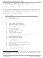
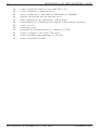
DESCRIPTION OF THE CONTROL CARDS
9-78
9.2.32
1
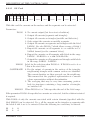
LS
6
10
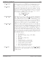
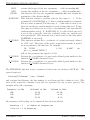
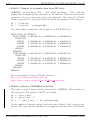
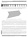
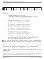
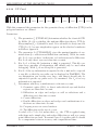
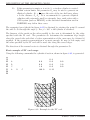
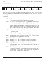
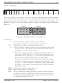
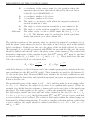
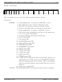
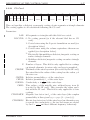
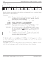
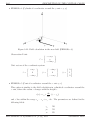
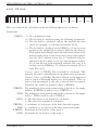
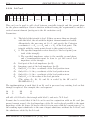
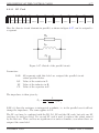
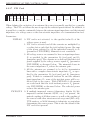
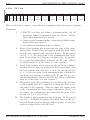
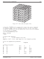
LS Card
15
20
25
30
40
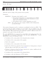
LAB
INT INT INT INT INT
STR STR STR STR STR
50
60
RS
LS
CS
REAL
REAL
REAL
70
REAL
80
REAL
90
REAL
100
REAL
110
REAL
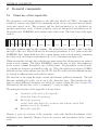
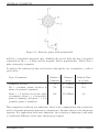
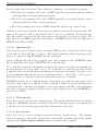
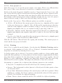
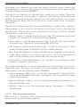
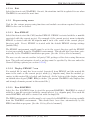
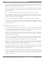
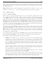
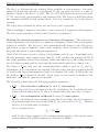
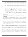
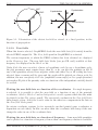
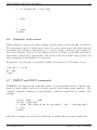
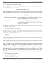
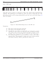
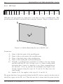
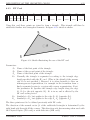
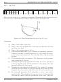
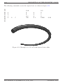
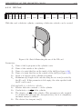
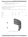
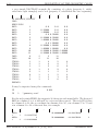
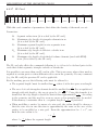
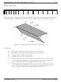
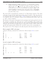
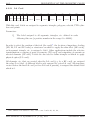
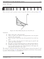
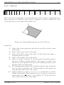
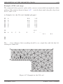
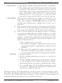
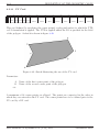
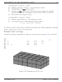
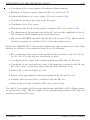
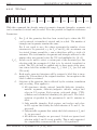
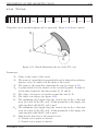
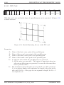
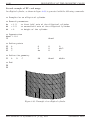
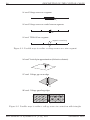
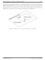
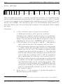
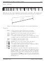
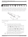
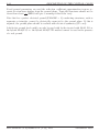
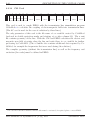
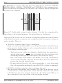
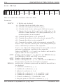
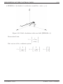
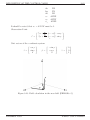
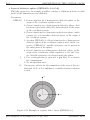
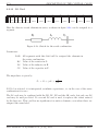
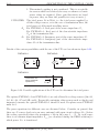
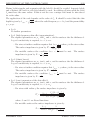
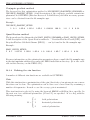
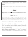
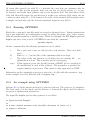
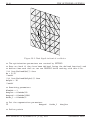
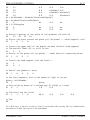
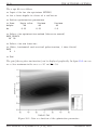
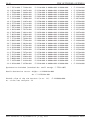
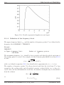
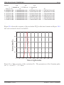
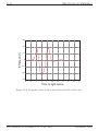
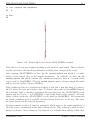
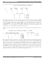
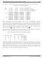
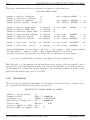
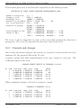
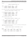
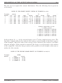
Here the discrete circuit elements in series, as shown in figure 9-28, can be assigned to a
segment.
Figure 9-28: Sketch for the serial combination
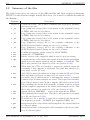
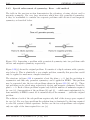
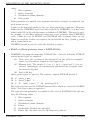
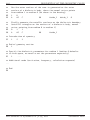
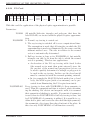
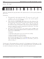
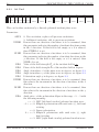
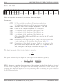
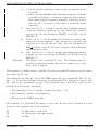
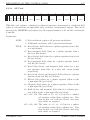
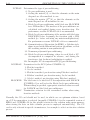
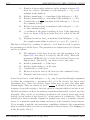
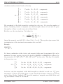
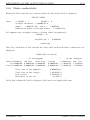
Parameters:
LAB
RS
LS
CS
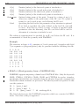
All segments with this label will be assigned the elements in
the series combination.
Value of the resistor in Ω.
Value of the inductor in H.
Value of the capacitor in F.
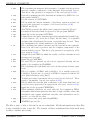
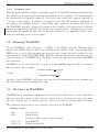
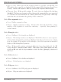
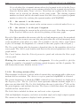
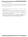
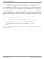
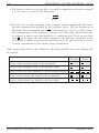
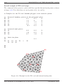
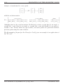
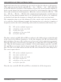
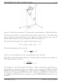
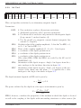
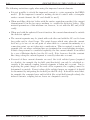
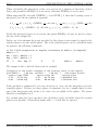
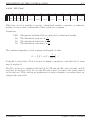
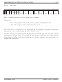
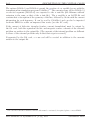
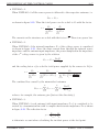
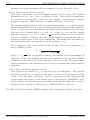
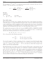
The impedance is given by
Zs = Rs + jωLs +
1
.
jωCs
If CS=0 is selected, it is interpreted as infinite capacitance, i.e. in the case of the series
combination it is zero.
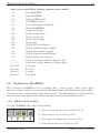
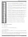
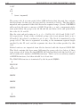
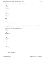
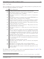
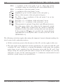
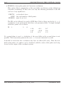
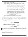
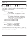
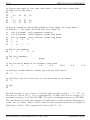
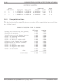
The LS card may be combined with the LD, LP, LZ and the SK cards, but only one LS
card may be used per label. If a second LS card is used, it replaces the values entered
by the first one. This card has no significance for surface elements, even when these are
assigned the same label.
EM Software & Systems-S.A. (Pty) Ltd
December 2002