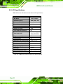
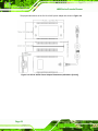
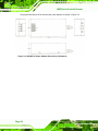
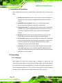
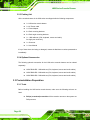
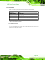
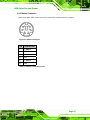
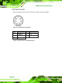
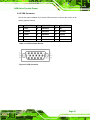
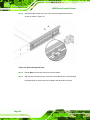
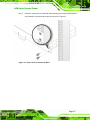
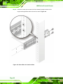
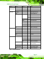
1
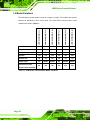
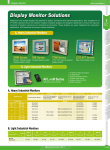
LKM Series Console Drawer Page 1 LKM Series Console Drawer REVISION HISTORY Title LKM Series Console Drawer User Manual Revision Number Description Date of Issue 1.0 Initial release November 2006 ABOUT THIS MANUAL This document covers the description and installation instructions for the LKM Series console drawers. COPYRIGHT NOTICE This document is copyrighted 2006, by IEI Technology Corp. All rights are reserved. IEI Technology Corp. reserves the rights to alter the products described in this manual at any time without prior notice. This document contains proprietary information protected by copyright. All rights are reserved. No part of this manual may be reproduced by any mechanical, electronic, or other means in any form without prior written permission of the manufacturer. Information provided in this manual is intended to be accurate and reliable. However, IEI Technology Corp. assumes no responsibility for use of this manual, nor for any infringements upon the rights of third parties, which may result from such use. Page 2 LKM Series Console Drawer SAFETY PRECAUTIONS Prior to installing, moving, and modifying the console, make sure the power is turned off and the power cord is disconnected. Do not apply voltage levels that exceed the specified voltage range. Doing so will cause fire or an electrical shock. Electric shocks can occur if the console chassis is opened. Do not drop or insert any objects into the ventilation openings of the console. If considerable amounts of dust, water, or fluids entered the console, turn off the power supply immediately, unplug the power cord, and contact the console vendor. Explosions may occur with installations in environments where flammable gases are present. FURTHER PRECAUTIONS Do not drop the console against a hard surface. Do not strike or exert excessive force onto the LCD panel. Touching the LCD panel using a sharp object will damage it. Avoid environments exposed to direct sunlight, dust, or chemical vapors. The ambient temperature of the installation site should be observed and controlled to avoid overheating the console. Condensation might form inside the console chassis if exposed to sudden changes in temperature. Carefully route the power cord so that people cannot step on it. Do not place anything over the power cord. If the console should be left unused for an extended period of time, disconnect it from its power source to avoid damage by transient over-voltage. If any of the following situations arise, have the console checked by qualified service personnel: o o The power cord or plug is damaged. Liquid has penetrated into the console. Page 3 LKM Series Console Drawer o o The console has been exposed to moisture. The console does not work properly, or cannot be made to work according to the user manual. o o The console has been dropped and damaged. The console shows obvious signs of damage. WARNING! Any changes or modifications made to the console that are not expressly approved by the relevant standards could void the authority to operate the console. ADDITIONAL INFORMATION AND ASSISTANCE MAINTENANCE AND CLEANING Prior to cleaning any part or component of the console, please read the details below. Except for the LCD panel, never spray or squirt liquids directly onto any other components. To clean the LCD panel, gently wipe it with a piece of soft dry cloth or a slightly moistened cloth. The interior of the console does not require cleaning. Keep fluids away from the console interior. Be cautious of all small removable components when vacuuming the console. Turn the system off before cleaning the console. Never drop any objects or liquids through the openings of the console. Be cautious of any possible allergic reactions to solvents or chemicals used when cleaning the console. Avoid eating, drinking and smoking within vicinity of the console. Page 4 LKM Series Console Drawer CLEANING TOOLS Some components in the console may only be cleaned using a product specifically designed for the purpose. In such case, the product will be explicitly mentioned in the cleaning tips. Below is a list of items to use when cleaning the console. Cloth – Although paper towels or tissues can be used, a soft, clean piece of cloth is recommended when cleaning the console. Water or rubbing alcohol – A cloth moistened with water or rubbing alcohol can be used to clean the console. Using solvents – The use of solvents is not recommended when cleaning the console as they may damage the plastic parts. Vacuum cleaner – Using a vacuum specifically designed for computers is one of the best methods of cleaning the console. Dust and dirt can restrict the airflow in the console and cause its circuitry to corrode. Cotton swabs - Cotton swaps moistened with rubbing alcohol or water are excellent tools for wiping hard to reach areas. Foam swabs - Whenever possible, it is best to use lint free swabs such as foam swabs for cleaning. ESD PRECAUTIONS Observe all conventional anti-ESD methods while handling the components contained within the console should the need arise. The use of a grounded wrist strap and an anti-static work pad is recommended. Avoid dust and debris or other static-accumulating materials in the work area. Page 5 LKM Series Console Drawer CONVENTIONS USED IN THIS MANUAL WARNING! Warnings appear where overlooked details may cause damage to the equipment or result in personal injury. Warnings should be taken seriously. Warnings are easy to recognize. The word “warning” is written as “WARNING,” both capitalized and bold and is followed by text in italics. The italicized text is the warning message. CAUTION! Cautionary messages should also be heeded to helps reduce the chance of losing data or damaging the system. Cautions are easy to recognize. The word “caution” is written as “CAUTION,” both capitalized and bold and is followed by text in italics. The italicized text is the cautionary message. NOTE: These messages inform the reader of essential but non-critical information. These messages should be read carefully as any directions or instructions contained therein can help avoid making mistakes. Notes are easy to recognize. The word “note” is written as “NOTE,” both capitalized and bold and is followed by text in italics. The italicized text is the cautionary message. Lists Bulleted Lists: Bulleted lists are statements of non-sequential facts that can be read in any order. Each statement is preceded by a round black dot “•” or bullets in other shapes. Numbered Lists: Numbered lists describe sequential steps that should be followed in order. Page 6 LKM Series Console Drawer Table of Contents 1 INTRODUCTION................................................................................................... 13 1.1 LKM SERIES CONSOLE DRAWER OVERVIEW ........................................................... 14 1.2 LKM SERIES CONSOLE DRAWER FEATURES ............................................................ 15 1.3 LKM SERIES CONSOLE DRAWER BENEFITS ............................................................. 15 1.4 MODEL VARIATIONS ................................................................................................. 16 1.5 MODEL OPTIONS ...................................................................................................... 17 1.6 MECHANICAL OVERVIEW ......................................................................................... 17 1.6.1 LKM-926 Series Overview............................................................................... 17 1.6.2 LKM-926 Keyboard Tray ................................................................................. 18 1.6.3 LKM-926 Side View ......................................................................................... 20 1.6.4 LKM-926 Access Door..................................................................................... 21 1.6.5 LKM-926 Rear View......................................................................................... 21 1.6.6 LKM-935 Series Overview............................................................................... 22 1.6.7 KVMA 8-Port Switch........................................................................................ 23 1.7 CERTIFICATIONS ....................................................................................................... 23 1.8 MAINTENANCE AND TROUBLESHOOTING ................................................................. 23 2 DETAILED SPECIFICATIONS ........................................................................... 25 2.1 SERIES SPECIFICATIONS ........................................................................................... 26 2.2 PHYSICAL DIMENSIONS ............................................................................................ 27 2.2.1 General Physical Dimensions.......................................................................... 27 2.2.2 LKM-926 Physical Dimensions ....................................................................... 28 2.2.3 LKM-935 Physical Dimensions ....................................................................... 29 2.3 LCD SPECIFICATIONS .............................................................................................. 30 2.4 POWER ADAPTERS ................................................................................................... 31 2.4.1 5V/12V AC/DC Power Adapter........................................................................ 31 2.4.2 24V/48V DC Input Power Adapters................................................................. 33 3 INSTALLATION .................................................................................................... 35 3.1 INSTALLATION PRECAUTIONS ................................................................................... 36 3.2 UNPACKING.............................................................................................................. 36 Page 7 LKM Series Console Drawer 3.2.1 Packaging ........................................................................................................ 36 3.2.2 Unpacking Procedure ...................................................................................... 37 3.2.3 Packing List ..................................................................................................... 38 3.2.4 Optional Accessories........................................................................................ 38 3.3 PRE-INSTALLATION PREPARATION ............................................................................ 38 3.3.1 Tools ................................................................................................................. 38 3.4 CONNECTORS ........................................................................................................... 39 3.4.1 Audio Connector .............................................................................................. 39 3.4.2 Keyboard Connector ........................................................................................ 40 3.4.3 Mouse Connector ............................................................................................. 41 3.4.4 Power Connector ............................................................................................. 42 3.4.5 VGA Connector ................................................................................................ 43 3.5 MOUNTING THE LKM SERIES CONSOLE DRAWER ................................................... 44 3.5.1 Rack Mounting ................................................................................................. 44 3.6 CABLING .................................................................................................................. 49 4 ON-SCREEN-DISPLAY (OSD) AND LCD MODULE (LCM) CONTROLS .. 51 4.1 OSD CONTROLS ...................................................................................................... 52 4.1.1 OSD Buttons..................................................................................................... 52 4.1.2 OSD Menu Structure ........................................................................................ 52 4.1.3 Brightness and Contrast Menu ........................................................................ 54 4.1.4 Color Menu ...................................................................................................... 55 4.1.4.1 Color Temperature Sub-Menu .................................................................. 56 4.1.4.2 User Sub-Menu ......................................................................................... 57 4.1.5 Image Menu ..................................................................................................... 58 4.1.6 Tools Menu ....................................................................................................... 59 4.1.6.1 OSD Sub-Menu......................................................................................... 60 4.2 LCM CONTROLS ...................................................................................................... 61 4.2.1 LCM Buttons .................................................................................................... 61 4.2.2 LCM Functions ................................................................................................ 62 4.2.2.1 Manually Switching Stations .................................................................... 62 4.2.2.2 Cycling Through Stations ......................................................................... 62 4.2.2.3 Station Name Editing ................................................................................ 62 A CERTIFICATIONS ................................................................................................ 65 Page 8 LKM Series Console Drawer A.1 ROHS COMPLIANT.................................................................................................. 66 INDEX.............................................................................................................................. 67 Page 9 LKM Series Console Drawer List of Figures Figure 1-1: LKM-926 General Overview ....................................................................18 Figure 1-2: LKM-926 Keyboard Tray..........................................................................19 Figure 1-3: LKM-926 Side View ..................................................................................20 Figure 1-4: LKM-926 Access Door.............................................................................21 Figure 1-5: LKM-926 Rear View..................................................................................21 Figure 1-6: LKM-935 Series Overview .......................................................................22 Figure 1-7: KVMA 8-Port Switch ................................................................................23 Figure 2-1: LKM-926 Physical Dimensions (millimeters) ........................................28 Figure 2-2: LKM-935 Physical Dimensions (millimeters) ........................................29 Figure 2-3: 5V/12V AC/DC Power Adapter ................................................................31 Figure 2-4: 5V/12V AC/DC Power Adapter Dimensions (millimeters [inches]) .....32 Figure 2-5: 24V/48V DC Power Adapter Dimensions (millimeters) ........................34 Figure 3-1: Keyboard Connector ...............................................................................40 Figure 3-2: Mouse Connector ....................................................................................41 Figure 3-3: 5V/12V Power Connector ........................................................................42 Figure 3-4: VGA Connector ........................................................................................43 Figure 3-5: Attach the Rack Mounting Bracket ........................................................45 Figure 3-6: Attach the Angle Bracket ........................................................................46 Figure 3-7: Secure Front of Console to Rack...........................................................47 Figure 3-8: Secure Rear of Console to Rack ............................................................48 Figure 3-9: Rear Panel Connections .........................................................................49 Figure 4-1: OSD Control Buttons...............................................................................52 Figure 4-2: Brightness and Contrast Menu ..............................................................54 Figure 4-3: Color Menu ...............................................................................................55 Figure 4-4: Color Temperature Sub-Menu ................................................................56 Figure 4-5: User Sub-Menu ........................................................................................57 Figure 4-6: Image Menu ..............................................................................................58 Page 10 LKM Series Console Drawer Figure 4-7: Tools Menu ...............................................................................................59 Figure 4-8: OSD Sub-Menu.........................................................................................60 Figure 4-9: LCM Control Buttons...............................................................................61 Page 11 LKM Series Console Drawer List of Tables Table 1-1: LKM Series Console Drawer Model Variations ......................................16 Table 2-1: LKM Series Specifications .......................................................................26 Table 2-2: General Physical Dimensions ..................................................................27 Table 2-3: LKM Series console drawer LCD Specifications ...................................30 Table 2-4: 5V/12V AC/DC Power Adapter Specifications ........................................31 Table 2-5: 24V/48V DC Power Adapter Specifications ............................................33 Table 3-1: Rear Panel Connectors.............................................................................39 Table 3-2: Keyboard Connector Pinouts ..................................................................40 Table 3-3: Mouse Connector Pinouts........................................................................41 Table 3-4: 5V/12V Power Connector Pinouts ...........................................................42 Table 3-5: VGA Connector Pinouts ...........................................................................43 Table 4-1: OSD Menu Structure .................................................................................53 Page 12 LKM Series Console Drawer Chapter 1 1 Introduction Page 13 LKM Series Console Drawer 1.1 LKM Series Console Drawer Overview The LKM Series console drawer is designed for IT professionals with up to eight ports for leveraging the power of existing server networks with minimal intrusion. Highly efficient, the LKM Series console drawer allows centralized access and control of up to eight computers from an integrated 1U console with a built-in 15” LCD display, one or eight port KVMA switch, keyboard and touch pad. The LKM Series console drawer is designed to deliver considerable return on investment. Saving time, money and valuable server room real estate, it can be rack mounted at any user-height. With a host of advanced features designed to protect your investment, the series includes: intelligent OSD (On Screen Display) menus, hot key switching, auto-sensing of computers and multi-language support. Whether it’s in educational, government, or corporate sectors, the LKM Series console drawer provides network and IT managers a stable management tool for multiple computer access and control. Page 14 LKM Series Console Drawer 1.2 LKM Series Console Drawer Features Some of the features of the LKM Series console drawer include: Ability to connect up to 8 computers Keyboard, mouse, audio and VGA connection ports for each computer 15" high brightness TFT LCD display Standard (PS/2) keyboard and touch pad Keyboard languages supported: German, English, French, Italian, Japanese, Russian, Spanish and Traditional Chinese Two internal speakers for stereo audio output 1U high slim body design saves rack space LCD module (LCM) - channel change control, auto scan control, programmable station naming Hot Pluggable - add or remove computers without having to power down the switch Supported OSes: Windows 98SE, 2000, XP, ME, Linux and Unix 1.3 LKM Series Console Drawer Benefits Some of the benefits of the LKM Series console drawer include: Control and access multiple computers from a central user console instead of moving from one to another. Save hundreds of dollars in equipment, space, and power costs as there is no need for additional peripherals for each computer. Installation is as simple as connecting cables between the KVMA switch and computers. Ideal for an Internet data center, server room, testing lab, and network-operating center where multiple computers are required. Page 15 LKM Series Console Drawer 1.4 Model Variations The LKM Series console drawer comes in a variety of models. The models have special features as identified by their model name. The LKM Series console drawer model LKM-926(8)G(C)-(L) LKM-926(8)G(C)T-(L) LKM-926(8)G(C)C-(L) LKM-935(8)G(C)-(L) LKM-935(8)G(C)T-(L) LKM-935(8)G(C)C-(L) variations are listed in Table 1-1. LCD Size 15” 15” 15” 15” 15” 15” Keyboard Yes Yes Yes Yes Yes Yes Mouse Yes Yes Yes Yes Yes Yes Speaker Yes Yes Yes Yes Yes Yes Drawer Size 1U 1U 1U 1U 1U 1U Power Input AC 48VDC 24VDC AC 48VDC 24VDC No No No Yes Yes Yes Separate LCD and Keyboard Accessibility Table 1-1: LKM Series Console Drawer Model Variations Page 16 LKM Series Console Drawer 1.5 Model Options Table 1-1 lists the standard features for the LKM Series console drawer model variations. However, there are a variety of additional options available for the LKM Series console drawer as identified by specific product codes. The product code options for the LKM Series console drawer are: (8) – specifies an eight port KVMA switch; these models also include an LCD module (LCM) on the keyboard tray. (C) – specifies color o o B: black W: white (L) – specifies keyboard language o o o o o o o o DE: German EN: English FR: French IT: Italian JP: Japanese RU: Russian SP: Spanish TW: Traditional Chinese For example, LKM-9268GB-EN would indicate an LKM-926 model with an eight-port KVMA switch, black color with an English keyboard. 1.6 Mechanical Overview This section describes a general physical overview of the LKM series console drawers. 1.6.1 LKM-926 Series Overview The LKM-926 series console drawer consists of a rail-mounted TFT LCD and keyboard tray within a heavy-duty steel drawer. With the use of a mounting kit, the console drawer can easily be mounted to a standard 19” rack. Figure 1-1 shows an overview of the LKM-926 series console drawer. Page 17 LKM Series Console Drawer Figure 1-1: LKM-926 General Overview 1.6.2 LKM-926 Keyboard Tray The keyboard tray consists of the following items: 87-key keyboard Left and right speakers LCD ON/OFF button Speaker ON/OFF button OSD control buttons Keyboard lock LEDs Touchpad with left and right-click buttons LCM display and control buttons (KVMA 8-port models only) Page 18 LKM Series Console Drawer Figure 1-2 shows the LKM-926 series console drawer keyboard tray. Figure 1-2: LKM-926 Keyboard Tray Page 19 LKM Series Console Drawer 1.6.3 LKM-926 Side View The sides of the console drawer have holes for rack mounting. Refer to Section 3.5 for complete mounting details. Figure 1-3 shows the side view of the LKM-926 series console drawer. Figure 1-3: LKM-926 Side View Page 20 LKM Series Console Drawer 1.6.4 LKM-926 Access Door The front of the console drawer consists of an access door with two spring-loaded, freewheeling retention screws for securing the access door when the LCD and keyboard are in the stowed position. Also located on the front of the console drawer are two metal clips with slotted holes for rack mounting. Refer to Section 3.5 for complete mounting details. Figure 1-4 shows the access door of the LKM-926 series console drawer. Figure 1-4: LKM-926 Access Door 1.6.5 LKM-926 Rear View The rear panel of the drawer consists of industry standard VGA, keyboard, mouse and audio connectors, as well as a power connector and cooling vents. Figure 1-5 shows the rear view of the LKM-926 series console drawer. Figure 1-5: LKM-926 Rear View Page 21 LKM Series Console Drawer 1.6.6 LKM-935 Series Overview The LKM-935 series console drawer is similar to the LKM-926 series with the following notable exceptions: The access door and LCD screen each have an additional handle for easy access. The LCD screen and keyboard tray can move independently of one another so that the LCD screen can be viewed while the keyboard tray is in the stowed position. Note that the keyboard tray cannot be accessed independently of the LCD screen. The sides of the drawer each have four holes for rack mounting (for a total of eight holes, not including those found on the front of the drawer). Refer to Section 3.5 for complete mounting details. Figure 1-6 shows the side view of the LKM-935 series console drawer. Figure 1-6: LKM-935 Series Overview Page 22 LKM Series Console Drawer 1.6.7 KVMA 8-Port Switch The KVMA 8-port switch can be used to connect up to eight systems to the LKM series console drawer. Each system can be connected to the console via its own standard audio, VGA, keyboard and mouse connectors. Each system can be easily accessed through the LCM on the keyboard tray (see Figure 1-2). Figure 1-7 shows the KVMA 8-port switch. Figure 1-7: KVMA 8-Port Switch 1.7 Certifications All LKM series console drawer models comply with the following international standard: RoHS For a more detailed description of this standard, please refer to Appendix A. 1.8 Maintenance and Troubleshooting All LKM series console drawer models require no maintenance and should provide trouble-free service. If any component of an LKM series console drawer fails to operate, malfunctions, or otherwise appears to be broken, do not attempt to fix it. Return the malfunctioning LKM series console drawer in its entirety to the original reseller, vendor or to IEI for repair or replacement. Page 23 LKM Series Console Drawer THIS PAGE IS INTENTIONALLY LEFT BLANK Page 24 LKM Series Console Drawer Chapter 2 2 Detailed Specifications Page 25 LKM Series Console Drawer 2.1 Series Specifications Table 2-1 shows the LKM Series console drawer specifications. LCD Type 15" TFT Input Interface XGA Max. Resolution 1024x768 Backlight MTBF 50,000 Hrs Contrast 400:1 LCD Color 262K Brightness (cd/m2) 350 Power Adapter 42W AC/DC Adapter Chassis Heavy-duty steel View Angle (H / V) 60(left), 60(right), 40(up), 60(down) OSD function Yes Mounting 19” Rack Mount Rack Height 1U Keyboard 87 Keys – Slim Size Touch Pad Yes – with 2 buttons LCM 8 Port KVMA Models Only Independent KB/LCD Trays LKM-926 series = No, LKM-935 series = Yes Dimensions (WxHxD) (mm) LKM-926 series = 482 x 323.25 x 903.29 LKM-935 series = 482 x 366.5 x 942.08 Weight (Gross/Net) 17Kg / 11.08Kg Color Black (Pantone Black C), White (Pantone 413C) Vibration 5 ~ 17 Hz, 0.1” double amplitude displacement 17 ~ 640 Hz, 1.5G acceleration peak to peak Shock 10G acceleration peak to peak (11ms) Humidity 5 ~ 95%, non-condensing Operation Temperature 0~50°C Table 2-1: LKM Series Specifications Page 26 LKM Series Console Drawer 2.2 Physical Dimensions The following sections describe the physical dimensions for each model of the LKM Series console drawer. 2.2.1 General Physical Dimensions General physical dimensions for the LKM Series console drawers are shown in Table 2-2. Model Width Height Depth (mm) (mm) (mm) LKM-926 482 323.25 903.29 LKM-935 482 366.5 942.08 Table 2-2: General Physical Dimensions Page 27 LKM Series Console Drawer 2.2.2 LKM-926 Physical Dimensions The physical dimensions of the LKM-926 are shown in Figure 2-1. Figure 2-1: LKM-926 Physical Dimensions (millimeters) Page 28 LKM Series Console Drawer 2.2.3 LKM-935 Physical Dimensions The physical dimensions of the LKM-935 are shown in Figure 2-2. Figure 2-2: LKM-935 Physical Dimensions (millimeters) Page 29 LKM Series Console Drawer 2.3 LCD Specifications Table 2-3 lists the LKM Series console drawer LCD specifications. Size 15" Mfr./Model AUO/G150XG01 Resolution (pixel) XGA (1024 x 768) Active Area (mm) 304.1 x 228.1 Pixel Pitch (mm) 0.297 Mode TN Number of Colors 262K Color Saturation (NTSC%) 60 View Angle (H/V) 60(left), 60(right), 40(up), 60(down) Brightness (cd/m²) 350 Contrast Ratio 400 : 1 Response Time (ms) (at 25°C) 16ms (Tr+Tf) Power Consumption (W) 11.5 Interface 1ch LVDS Supply Voltage (V) 3.3 Backlight 2 CCFL Outline Dimensions (mm) 326.5 x 253.5 x 12.0 Lamp Life (hrs) 50,000 Table 2-3: LKM Series console drawer LCD Specifications Page 30 LKM Series Console Drawer 2.4 Power Adapters 2.4.1 5V/12V AC/DC Power Adapter Table 2-4 lists the 5V/12V AC/DC power adapter specifications. MFR./Model Sinpro/SPU45E-201 Power 45 Watt AC/DC Adapter General Description Universal Input 90 to 264 VAC EMI Meets FCC Part-15/CISPR 22 Class B MTBF 100Khrs Input Voltage Range 90-264VAC Input Frequency 47-63 Hz Inrush Current 30A max. (Cold Start) Hold-up Time 10mS typical Leakage Current 0.75mA max. Short Circuit Protection Continuous Over-voltage Protection Yes Continuous Output Power 42W max. Hi-pot Isolation: Input / Output 42/42VDC Table 2-4: 5V/12V AC/DC Power Adapter Specifications The 5V/12V AC/DC power adapter is shown in Figure 2-3. Figure 2-3: 5V/12V AC/DC Power Adapter Page 31 LKM Series Console Drawer The physical dimensions of the 5V/12V AC/DC power adapter are shown in Figure 2-4. Figure 2-4: 5V/12V AC/DC Power Adapter Dimensions (millimeters [inches]) Page 32 LKM Series Console Drawer 2.4.2 24V/48V DC Input Power Adapters Table 2-5 lists the 24V/48V DC power adapter specifications. MFR./Model EMI Standards 24V DC Input 48V DC Input Skynet / ACE-023C Skynet / ACE-023T FCC Docket 20780 curve“B” EN 55022“B” IEC-61000-4-2: 4KV contact; 8KV air discharge criterion B EMS Standards IEC-61000-4-3: 3V/M with 80% AM criterion A IEC-61000-4-4: 2KV criterion B Input Voltage Range 18VDC - 32VDC Input Current 2.5A max. at 24VDC Inrush Current 15A max. at 24VDC (25º Cold Start) Output Load Range 36VDC - 72VDC +5V output, 4A rated load +12V output, 0.75A rated load Output Power >30W at 24VDC Ripple and Noise >1.2% of output voltage peak to peak Line Regulation >±1% at rated load Load Regulation 5V >±5% at 60% rated load, 24VDC input 12V >±4% at 60% rated load, 24VDC input Short Circuit Protection Continuous Over-voltage Protection Yes Humidity 20 ~ 95%, non-condensing Operation Temperature 0 ~ 50°C Storage Temperature -40 ~ 85°C Table 2-5: 24V/48V DC Power Adapter Specifications Page 33 LKM Series Console Drawer The physical dimensions of the 24V/48V DC power adapter are shown in Figure 2-5. Figure 2-5: 24V/48V DC Power Adapter Dimensions (millimeters) Page 34 LKM Series Console Drawer Chapter 4 3 3 Installation Page 35 LKM Series Console Drawer 3.1 Installation Precautions When installing the LKM series console drawer, please follow the precautions listed below: Read the user manual: The user manual provides a complete description of the LKM series console drawer, installation instructions and configuration options. DANGER! Disconnect Power: Power to the console drawer must be disconnected when installing the LKM series console drawer. Qualified Personnel: The LKM series console drawer must be installed and operated only by trained and qualified personnel. Maintenance may only be carried out by qualified personnel who are familiar with the associated dangers. Mounting: Since the LKM series console drawer may weigh up to 11Kg, please ensure at least two people assist with mounting the drawer. Air Circulation: Make sure there is sufficient air circulation when installing the LKM series console drawer. The LKM series console drawer’s cooling vents must not be obstructed by any objects. Blocking the vents can cause overheating of the LKM series console drawer. Grounding: The LKM series console drawer should be properly grounded. The voltage feeds must not be overloaded. Adjust the cabling and provide external overcharge protection per the electrical values indicated on the label attached to the power adapter. 3.2 Unpacking 3.2.1 Packaging When shipped, the LKM series console drawer is wrapped in a plastic bag. Two polystyrene ends are placed on either side of the console drawer. The console drawer is then placed into a first (internal) cardboard box. This box is then sealed and placed into a second (external) cardboard box. The second box is also sealed. Two bags containing accessory items are placed with the console drawer in the internal (first) box. Page 36 LKM Series Console Drawer 3.2.2 Unpacking Procedure To unpack the LKM series console drawer, follow the steps below: WARNING: The LCD screen has a protective plastic cover stuck to the screen. Remove the plastic cover only after the LKM series console drawer has been properly installed. This ensures the screen is protected during the installation process. Step 1: Use a box cutter, a knife or a sharp pair of scissors to cut the tape that seals the top side of the external (second) box. Step 2: Open the external (second) box. Step 3: Use a box cutter, a knife or a sharp pair of scissors to cut the tape that seals the top side of the internal (first) box. Step 4: Lift the console drawer out of the boxes. Step 5: Remove both polystyrene ends, one from each side. Step 6: Pull the plastic cover off the console drawer. Step 7: Make sure all the components listed in the packing list are present. Step 0: Page 37 LKM Series Console Drawer 3.2.3 Packing List All the console drawers in the LKM series are shipped with the following components: 1 x LKM series console drawer 1 x AC Power cable 1 x Power Adapter 2 x Rack mounting brackets 2 x Rack angle mounting brackets 1 x 1.8M cable set (VGA, keyboard, mouse and audio) for single port model only 1 x Screw set 1 x User Manual If any of these items is missing or damaged, contact the distributor or sales representative immediately. 3.2.4 Optional Accessories The following optional accessories for the LKM series console drawers can be ordered separately: LKM-CB18A-RS: 1.8M cable set (VGA, keyboard, mouse and audio cables) LKM-CB30A-RS: 3.0M cable set (VGA, keyboard, mouse and audio cables) LKM-CB50A-RS: 5.0M cable set (VGA, keyboard, mouse and audio cables) 3.3 Pre-installation Preparation 3.3.1 Tools Before installing the LKM series console drawer, make sure the following tools are on hand: Philips (crosshead) screwdriver: All the retention screws on the system are Philips screws. Page 38 LKM Series Console Drawer 3.4 Connectors Table 3-1 lists the rear panel connectors for the LKM series console drawers. Connector Type Audio connector 1 x audio jack Keyboard connector PS/2 connector Mouse connector PS/2 connector Power connector Mini DIN Plug With Lock (Thick Pin, 4 PIN) connector VGA connector HD-D-sub 15 female connector Table 3-1: Rear Panel Connectors 3.4.1 Audio Connector To receive audio signals from a system, use the rear panel audio jack to connect to a system’s line out audio jack connector. Page 39 LKM Series Console Drawer 3.4.2 Keyboard Connector Use the rear panel PS/2 keyboard connector to connect the console keyboard to a system. Figure 3-1: Keyboard Connector PIN DESCRIPTION 1 L_KDAT 2 NC 3 GND 4 5V 5 L_KCLK 6 NC Table 3-2: Keyboard Connector Pinouts Page 40 LKM Series Console Drawer 3.4.3 Mouse Connector Use the rear panel PS/2 mouse connector to connect the console mouse to a system. Figure 3-2: Mouse Connector PIN DESCRIPTION 1 L_MDAT 2 NC 3 GND 4 5V 5 L_MCLK 6 NC Table 3-3: Mouse Connector Pinouts Page 41 LKM Series Console Drawer 3.4.4 Power Connector Use the rear panel power connector to connect the console to the power adapter. Figure 3-3: 5V/12V Power Connector PIN DESCRIPTION PIN DESCRIPTION 2 COMMON 1 +5V 4 COMMON 3 +12V Shell GND Table 3-4: 5V/12V Power Connector Pinouts Page 42 LKM Series Console Drawer 3.4.5 VGA Connector Use the rear panel standard 15-pin female VGA connector to connect the monitor to the system graphics interface. PIN DESCRIPTION PIN DESCRIPTION PIN DESCRIPTION 1 RED 6 GROUND 11 NC 2 GREEN 7 GROUND 12 DDCDAT 3 BLUE 8 GROUND 13 HSYNC 4 NC 9 NC 14 VSYNC 5 GROUND 10 GROUND 15 DDCCLK Table 3-5: VGA Connector Pinouts Figure 3-4: VGA Connector Page 43 LKM Series Console Drawer 3.5 Mounting the LKM Series Console Drawer Each LKM series console drawer is shipped with an installation kit for mounting the drawer into a rack. Refer to the following section for instructions on rack mounting the LKM series console drawer. 3.5.1 Rack Mounting The LKM series console drawer can be mounted to the rack posts of a standard 19” rack cabinet. Make sure that all cabling is correctly attached and carefully routed when installing the LKM series console drawer. Follow the steps below to mount the LKM series console drawer into a rack. NOTE: At least two people are required to mount the LKM series console drawer. The rack or cabinet into which the LKM series console drawer is installed should provide adequate and sufficient ventilation, grounding, power source, and stability features. Step 1: Find the rack mounting kit in the box that the LKM series console drawer was shipped in. NOTE: In order to attach a rack-mounting bracket to an LKM-926 series console drawer, the rearmost cap screw must be removed from the side panel. Refer to Figure 1-3 for more information. Page 44 LKM Series Console Drawer Step 2: Attach one of the rack mounting brackets to the side of the console drawer with either two or four screws as required (see Figure 3-5). Figure 3-5: Attach the Rack Mounting Bracket Step 3: Repeat Step 2 for the other side of the console drawer. Page 45 LKM Series Console Drawer Step 4: Attach an angle bracket to the one of the rack mounting brackets with two screws as shown in Figure 3-6. Figure 3-6: Attach the Angle Bracket Step 5: Repeat Step 4 for the other side of the console drawer. Step 6: With the help of another person, insert the console drawer into a rack and align the slotted holes on the front face of the drawer with the holes in the rack. Page 46 LKM Series Console Drawer Step 7: Insert four screws (two on each side of the drawer’s front face) through the holes in the drawer’s front face and into the rack as seen in Figure 3-7. Figure 3-7: Secure Front of Console to Rack Page 47 LKM Series Console Drawer Step 8: Insert four screws (two on each side of the drawer) through the holes in the angle mounting bracket and into the rack as seen in Figure 3-8. Figure 3-8: Secure Rear of Console to Rack Page 48 Step 0: LKM Series Console Drawer 3.6 Cabling Each LKM series console drawer is shipped with a set of cables for connecting a system to the console. Figure 3-9 shows a detail of the cable connections on the LKM series console drawer rear panel. Up to eight systems can be connected to the console drawer with the use of a KVMA switch model. All cable connections to the KVMA switch are similar to those seen in Figure 3-9. Figure 3-9: Rear Panel Connections Page 49 LKM Series Console Drawer THIS PAGE IS INTENTIONALLY LEFT BLANK Page 50 LKM Series Console Drawer Chapter 4 4 On-Screen-Display (OSD) and LCD Module (LCM) Controls Page 51 LKM Series Console Drawer 4.1 OSD Controls 4.1.1 OSD Buttons There are several on-screen-display (OSD) control buttons on the keyboard tray of the LKM series console drawers (Figure 4-1). Use the Menu/Enter button to initiate the OSD controls menu or to enter adjusted values for OSD options. Use the Left and Right buttons to navigate through the OSD menu structure. Figure 4-1: OSD Control Buttons NOTE: Pressing the “Left” key while the OSD control menu is inactive brings up the brightness adjustment menu. Pressing the “Auto” key while the OSD control menu is inactive will automatically adjust the display for optimum view on the LCD screen. 4.1.2 OSD Menu Structure Table 4-1 shows the OSD menu structure for all models of the LKM series console drawers. Page 52 LKM Series Console Drawer Level 0 Level 1 Brightness and Brightness 0 to 100 Contrast Menu Contrast 0 to 100 Exit Return to Main Menu AutoColor Auto-adjusts the color sRGB Standard RGB mode Color Menu ColorTemp Image Menu Tools Menu Level 2 User Level 3 Value R 0 to 255 G 0 to 255 B 0 to 255 4200k Preset NTSC value 5000k Preset NTSC value 6500k Preset NTSC value 7500k Preset NTSC value 9300k Preset NTSC value Exit Return to Color Menu Exit Return to Main Menu AutoAdjust Auto-adjusts display values Width 0 to 100 Clock Phase 0 to 32 HPos 0 to 255 VPos 0 to 255 Exit Return to Main Menu OSD Factory Reset OSDTimeOut 0 to 60 OSDHPos 0 to 255 OSDVPos 0 to 255 Exit Return to Tools Menu Reset all display values to factory settings Sharpness 0 to 6 Overlapped Mode 640/720 Mode change Exit Return to Main Menu Table 4-1: OSD Menu Structure Page 53 LKM Series Console Drawer 4.1.3 Brightness and Contrast Menu The Brightness and Contrast menu is shown in Figure 4-2. Figure 4-2: Brightness and Contrast Menu Brightness: This item sets the brightness of screen, adjusting the offset value of ADC. Setting this value too high or too low will affect the quality of image. Contrast: This item sets the gain value of ADC. Adjusting this value too high or too low will worsen the quality of image. Exit: This item exits the Brightness and Contrast menu. Page 54 LKM Series Console Drawer 4.1.4 Color Menu The Color menu is shown in Figure 4-3. Figure 4-3: Color Menu The Color menu fine-tunes the palette of color hues for the LCD. AutoColor: This item automatically adjusts the color. sRGB: This item sets the color to standard RGB mode. ColorTemp: This enters the Color Temperature sub-menu (see Section 4.1.4.1). Exit: This item exits the Color menu. Page 55 LKM Series Console Drawer 4.1.4.1 Color Temperature Sub-Menu The Color Temperature sub-menu is shown in Figure 4-4. Figure 4-4: Color Temperature Sub-Menu User: This enters the User sub-menu (see Section 4.1.4.2). 4200: This item sets the display color temperature to NTSC standard 4200K. 5000: This item sets the display color temperature to NTSC standard 5000K. 6500: This item sets the display color temperature to NTSC standard 6500K. 7500: This item sets the display color temperature to NTSC standard 7500K. 9300: This item sets the display color temperature to NTSC standard 9300K. Page 56 LKM Series Console Drawer 4.1.4.2 User Sub-Menu The User sub-menu is shown in Figure 4-5. Figure 4-5: User Sub-Menu User: This item adjusts the balance among Red, Green, and Blue color hues if images look garish or unrealistic. Page 57 LKM Series Console Drawer 4.1.5 Image Menu The Image menu is shown in Figure 4-6. Figure 4-6: Image Menu The Image menu adjusts the screen position options. AutoAdjust: This item automatically adjusts the screen position. Width: This item adjusts the screen size in the horizontal direction. Clock Phase: This item adjusts the input signal and dot clock position (Analog only). HPos: This item adjusts the horizontal position of the display screen. VPos: This item adjusts the vertical position of the display screen. Exit: This item exits the Image menu. Page 58 LKM Series Console Drawer 4.1.6 Tools Menu The Tools menu is shown in Figure 4-7. Figure 4-7: Tools Menu The Tools menu has the following options: OSD: This enters the OSD sub-menu (see Section 4.1.6.1). Factory Reset: This item resets all display values to their factory settings. Sharpness: This item adjusts the sharpness level to preset values. This option may help reducing the softening edges around displayed objects. Overlapped Mode: This item toggles the DOS mode pixel resolution between 640 and 720. Exit: This item exits the Tools menu. Page 59 LKM Series Console Drawer 4.1.6.1 OSD Sub-Menu The OSD sub-menu is shown in Figure 4-8. Figure 4-8: OSD Sub-Menu OSDTimeOut: This item adjusts how many seconds the OSD screen stays visible before it disappears when OSD is left unattended. OSDHPos: This item adjusts the horizontal position of the OSD display screen. OSDVPos: This item adjusts the vertical position of the OSD display screen. Exit: This item exits the OSD sub-menu. Page 60 LKM Series Console Drawer 4.2 LCM Controls The LCM is used to control the display and switching status of systems connected to the console. 4.2.1 LCM Buttons There are three LCD module (LCM) control buttons and one LED (Figure 4-9) on the keyboard tray of the LKM series console drawers that have eight port connectors. Figure 4-9: LCM Control Buttons LED: This item indicates that the LCD is either in Auto Scan mode or Edit mode. AUTO / EDIT: This item initiates an auto-scan sequence for systems connected to the console and can be used to edit station names. UP: This item scrolls up through available stations and options. DOWN: This item scrolls down through available stations and options. Page 61 LKM Series Console Drawer 4.2.2 LCM Functions The following sections describe the LCM functions. 4.2.2.1 Manually Switching Stations When the LKM series console drawer is initially connected to a power source, "Power On" is displayed on the LCM; afterwards, "Station 001" is displayed indicating that the system connected to station 1 ports is currently active. Use the "UP" and "Down" button to activate control over other stations. The station range is from "station 000" to "station 007". 4.2.2.2 Cycling Through Stations Press the "AUTO/EDIT" button to activate the automatic switching function. Press the "AUTO/EDIT" button and the console will continuously cycle through all available stations at an interval of 10 seconds. Press the "AUTO/EDIT" button again to stop the cycling sequence. 4.2.2.3 Station Name Editing The station name editing functions allow users to input the name of each computer station on the LCM. The maximum number of input characters is 16. The following procedure is used as an example of how to add the name "ICP ALPHA SERVER" to "Station 001". Available characters for naming are: A to Z, 0 to 9, space and the following symbols: ! " # $ %&/()*+,-./=<>?@[]_ Step 1: Switch to "Station 001" on the LCM (see Section 4.2.2.1). Step 2: Press the "AUTO/EDIT" button for more than 3 seconds, or until a blinking cursor is seen on the LCM, to enter edit mode. Step 3: Press the "UP” or “DOWN" button until reaching the character "I". Step 4: Press the "AUTO/EDIT" button to select the "I" character. Step 5: Press the "UP” or “DOWN" button until reaching the character "C". Page 62 LKM Series Console Drawer Step 6: Press the "AUTO/EDIT" button to select the "C" character. Step 7: Repeat steps 5 and 6 until "ICP ALPHA SERVER" is written on the LCM. Step 8: Press the "AUTO/EDIT" button for more than 3 seconds, or until the blinking cursor disappears from the LCM, to exit edit mode. Step 0: Page 63 LKM Series Console Drawer THIS PAGE IS INTENTIONALLY LEFT BLANK Page 64 LKM Series Console Drawer Appendix A A Certifications Page 65 LKM Series Console Drawer A.1 RoHS Compliant All models in the LKM Series console drawer comply with the Restriction of Hazardous Materials (RoHS) Directive. This means that all components used to build the industrial workstations and the workstation itself are RoHS compliant. The RoHS Directive bans the placing on the EU market of new electrical and electronic equipment containing more than agreed levels of lead, cadmium, mercury, hexavalent chromium, polybrominated biphenyl (PBB) and polybrominated diphenyl ether (PBDE) flame retardants. Page 66 LKM Series Console Drawer 5 Index Page 67 LKM Series Console Drawer B I Backlight MTBF .........................................26 Input Interface ............................................26 Benefits ......................................................15 Installation Brightness..................................................26 Tools ......................................................38 Unpacking..............................................36 C K Cabling.......................................................49 Certifications ........................................23, 65 Keyboard....................................................26 Chassis ......................................................26 KVMA 8-Port Switch ..................................23 Color ..........................................................26 L Contrast .....................................................26 LCD Color ..................................................26 D Dimensions ................................................27 LKM-926 ................................................28 LKM-935 ................................................29 LCD Specifications.....................................30 LCD Type ...................................................26 LCM Controls LCM Buttons..........................................61 LCM Controls .............................................61 E LCM Functions...........................................62 ESD Precautions .........................................5 Cycling Through Stations.......................62 External Connectors Manually Switching Stations..................62 Audio .....................................................39 Station Name Editing .............................62 Keyboard ...............................................40 Mouse....................................................41 M Power ....................................................42 Maintenance ..............................................23 VGA .......................................................43 Max. Resolution .........................................26 Mechanical Overview.................................17 F Features.....................................................15 LKM-926 Series.....................................17 LKM-935 Series.....................................22 Model Options............................................17 H Humidity.....................................................26 Page 68 Model Variations ........................................16 Mounting ....................................................44 LKM Series Console Drawer O R Operation Temperature..............................26 Rack Height ...............................................26 Optional Accessories .................................38 RoHS .................................................. 23, 66 OSD Controls.............................................52 Brightness and Contrast Menu..............54 S Buttons ..................................................52 Safety Precautions.......................................3 Color Menu............................................55 Shock .........................................................26 Color Temperature Menu.......................56 Specifications .............................................25 Image Menu ..........................................58 OSD Menu.............................................60 T Tools Menu ............................................59 Touch Pad ..................................................26 User Menu.............................................57 Troubleshooting .........................................23 OSD Menu Structure .................................52 V P Packing List ...............................................38 Vibration.....................................................26 View Angle .................................................26 Power Adapter ...........................................26 24V/48V DC Input .................................33 5V/12V AC/DC.......................................31 Page 69