1
GDML USER’S GUIDE
Version 2.5
Page 1 of 50
Contents
GDML USER’S GUIDE........................................................................................................... 1 Contents .................................................................................................................................. 2 1. Introduction ....................................................................................................................... 4 2. Getting started ................................................................................................................... 5 2.1 Installation of GDML in Geant4................................................................................. 5 2.2 Running simple examples ........................................................................................... 5 3. GDMLSchema .................................................................................................................. 6 3.1 General structure ......................................................................................................... 6 3.1.1 Splitting GDML file using ENTITY ................................................................. 8 3.1.2 Multiple GDML files ........................................................................................ 8 3.2 Definitions .................................................................................................................. 9 3.2.1 Constants ........................................................................................................... 9 3.2.2 Quantities .......................................................................................................... 9 3.2.3 Variables............................................................................................................ 9 3.2.4 Positions ............................................................................................................ 9 3.2.5 Rotations.......................................................................................................... 10 3.2.6 Scales ............................................................................................................... 10 3.2.7 Matrices ........................................................................................................... 10 3.3 Materials ................................................................................................................... 12 3.3.1 Isotopes............................................................................................................ 12 3.3.2 Elements .......................................................................................................... 12 3.3.3 Materials .......................................................................................................... 13 3.4 Solids ........................................................................................................................ 14 3.4.1 Box .................................................................................................................. 14 3.4.2 Cone Segment ................................................................................................. 14 3.4.3 Ellipsoid .......................................................................................................... 14 3.4.4 Elliptical Tube ................................................................................................. 15 3.4.5 Elliptical Cone ................................................................................................. 15 3.4.6 Orb ................................................................................................................... 15 3.4.7 Paraboloid........................................................................................................ 16 3.4.8 Parallelepiped .................................................................................................. 16 3.4.9 Polycone .......................................................................................................... 17 3.4.10 Generic Polycone ............................................................................................ 17 3.4.11 Polyhedron ...................................................................................................... 18 3.4.12 Generic Polyhedron ......................................................................................... 19 3.4.13 Sphere .............................................................................................................. 19 3.4.14 Torus Segment................................................................................................. 20 3.4.15 Trapezoid – x & y varying along z .................................................................. 20 3.4.16 General Trapezoid ........................................................................................... 20 Page 2 of 50
3.4.17 Tube with Hyperbolic Profile .......................................................................... 21 3.4.18 Cut Tube .......................................................................................................... 21 3.4.19 Tube Segment .................................................................................................. 22 3.4.20 Twisted Box .................................................................................................... 22 3.4.21 Twisted Trapezoid ........................................................................................... 23 3.4.22 Twisted General Trapezoid ............................................................................. 23 3.4.23 Twisted Tube Segment .................................................................................... 24 3.4.24 Extruded Solid ................................................................................................. 24 3.4.25 Arbitrary Trapezoid (Arb8) ............................................................................. 25 3.4.26 Tessellated solid .............................................................................................. 26 3.4.27 Tetrahedron ..................................................................................................... 27 3.4.28 Using loops for solids ...................................................................................... 28 3.4.29 Boolean Solids................................................................................................. 28 3.5 Structure .................................................................................................................... 29 3.5.1 Loops ............................................................................................................... 30 3.5.2 Replicated Volumes ........................................................................................ 32 3.5.3 Parameterised Volumes ................................................................................... 33 3.5.3.1. Dimensions of Parameterised Box ............................................................. 34 3.5.3.2. Dimensions of Parameterised Tube ............................................................ 34 3.5.3.3. Dimensions of Parameterised Cone ............................................................ 35 3.5.3.4. Dimensions of Parameterised Orb .............................................................. 35 3.5.3.5. Dimensions of Parameterised Sphere ......................................................... 35 3.5.3.6. Dimensions of Parameterised Torus ........................................................... 36 3.5.3.7. Dimensions of Parameterised Hype ........................................................... 36 3.5.3.8. Dimensions of Parameterised Parallelepiped ............................................. 36 3.5.3.9. Dimensions of Parameterised Trapezoid .................................................... 37 3.5.3.10. Dimensions of Parameterised General Trapezoid ...................................... 37 3.5.3.11. Dimensions of Parametrised Polycone ....................................................... 38 3.5.3.12. Dimensions of Parametrised Polyhedron ................................................... 38 3.5.3.13. Dimensions of Parametrised Ellipsoid ....................................................... 38 3.5.4 GDML Modules .............................................................................................. 39 3.5.5 Volume Auxiliary Information........................................................................ 40
3.5.6
Auxiliary User Information ............................................................................. 41
3.6 Setup ......................................................................................................................... 42 4. Importing and exporting GDML files ............................................................................. 44 4.1 GDML Reading ........................................................................................................ 44 4.1.1 Importing GDML files into Geant4 Geometry ............................................... 44 4.2 GDML Writing ......................................................................................................... 45 4.2.1 Exporting Geant4 Geometry ........................................................................... 45 4.2.2 Exporting ST-Viewer CAD Geometry ............................................................ 46 5. User extensions to GDML using Geant4 ........................................................................ 47 5.1 A ‘redefine’ element ................................................................................................. 48 5.2 New Elements ........................................................................................................... 48 Page 3 of 50
1. Introduction
The Geometry Description Markup Language (GDML) is a specialized XML-based language
designed as an application-independent persistent format for describing the geometries of
detectors associated with physics measurements. It serves to implement “geometry trees”
which correspond to the hierarchy of volumes a detector geometry can be composed of, and
to allow to identify the position of individual solids, as well as to describe the materials they
are made of. Being pure XML, GDML can be universally used, and in particular it can be
considered as the format for interchanging geometries among different applications.
GDML consists of two elements, an XML definition part containing the set of rules and the
list of the legal elements to be used in constructing any GDML document, and the GDML
generating and processing code implemented in the client tools. The structure of the GDML
document is defined through a set of XML Schema Definition (XSD) files, which we call the
GDMLSchema. Any GDML geometry file must be valid with respect to the GDMLSchema.
The GDML file itself, can be either written by hand (in case GDML is used as the primary
geometry source) or generated automatically (in case GDML is used as an exchange or
persistency format) out of the application specific “in-memory” geometry tree using one of
the GDML “writers” called by the user application. The GDML reader is responsible for
parsing the GDML file and creating the in-memory representation of the geometry tree
specific for the user application.
This manual will focus on the Geant4 binding to GDML, which, starting from release 9.2 of
the simulation toolkit, it is now integrated in Geant4. The Root binding for GDML is
integrated within the Root framework; the user should refer to the general Root manual for
any information on importing and/or exporting GDML files to/from the Root geometry model.
The description of the GDMLSchema in Section 3, however, is application-independent and
therefore is relevant for both Geant4 and Root users.
GDML Schema is distributed with GDML Geant4 binding.
Page 4 of 50
2. Getting started
2.1 Installation of GDML in Geant4
Building the GDML module in Geant4 is optional; by default, the GDML plug-in is not built
along with the rest of the Geant4 libraries. In order to build the Geant4 module for GDML,
one needs to have:
• The XercesC parser pre-installed (presently GDML uses XercesC 3.1.2 version);
• The following environment variables set at the time the Geant4 libraries get built:
- XERCESROOT, specifying the path where the XercesC parser library and
headers are installed in the system;
G4LIB_BUILD_GDML set to "1".
Once the above setup is defined in the user's environment, the GDML module in Geant4
will be built using the standard build procedure applicable for Geant4.
2.2 Running simple examples
The Geant4 binding for GDML comes with three examples, which demonstrate the reading
and writing out of different geometry configurations from/to GDML files. The examples also
show how user can extend GDML and how to export ST-Viewer CAD Geometry. The
directories containing these examples can be found in the Geant4 distribution in the
$G4INSTALL/examples/extended/persistency/gdml directory. NOTE: in case of using
dynamic libraries, one needs to set the LD_LIBRARY_PATH variable to point to all the
necessary libraries (CLHEP, Geant4, and XercesC) before running the examples. Please
refer to the examples README files for more information.
Page 5 of 50
3. GDMLSchema
3.1 General structure
The GDML schema is a set of XSD files which define the structure of the GDML document
and its legal elements. The general structure of the GDML file can be seen below (with
some parts replaced by ‘...’ for brevity).
<?xml version="1.0" encoding="UTF-8"?>
<gdml xsi:noNamespaceSchemaLocation="schema/gdml.xsd">
<define>
…
<position name="TrackerinWorldpos" unit="mm" x="0" y="0" z="100"/>
</define>
<materials>
…
<element name="Nitrogen" formula="N" Z="7.">
<atom value="14.01"/>
</element>
<material formula=" " name="Air" >
<D value="1.290" unit="mg/cm3"/>
<fraction n="0.7" ref="Nitrogen" />
<fraction n="0.3" ref="Oxygen" />
</material>
</materials>
<solids>
…
<box lunit="mm" name="Tracker" x="50" y="50" z="50"/>
</solids>
<structure>
…
<volume name="World" >
<materialref ref="Air" />
<solidref ref="world" />
<physvol>
<volumeref ref="Tracker" />
<positionref ref="TrackerinWorldpos"/>
<rotationref ref="TrackerinWorldrot"/>
</physvol>
</volume>
</structure>
<setup name="Default" version="1.0" >
<world ref="World" />
</setup>
</gdml>
One can distinguish there five parts, each holding specific type of data.
The <define> ... </define> block contains numerical values of different constants,
positions, rotations and scales that will be used later on in the geometry construction.
The <materials> ...</materials> block contains definitions of all the materials used in the
given geometry. The supported forms are simple materials, which are made from one
element as well as mixtures. Mixtures can be composed on the basis of fraction of mass or
atom count.
The <solids> ... </solids> block is the collection of all solid definitions which are used in
the given geometry description. The presently supported solids are described in Section 3.4.
Page 6 of 50
Composite solids made using Boolean operation (union, subtraction, intersection) are also
supported.
The <structure> ... </structure> block contains the actual implementation of the
geometry tree together with the assignment of solids and materials. The hierarchy of
volumes is defined by specifying the daughter volumes (physvol) positioned inside a
volume. Constructions like assembly volumes, reflections, replicas and divisions are
possible. A more detailed discussion of the ‘structure’ block can be found in Section 3.5.
Finally, the <setup> ... </setup> block serves to specify the top volume of the geometry
tree. It is possible to define several "setups" within one file, allowing testing different
subparts (or different configurations included in the same file) of the geometry tree without
changing the GDML file.
Page 7 of 50
3.1.1 Splitting GDML file using ENTITY
Any GDML file can be split into several files, which are combined together during the
parsing by using the ENTITY statement. The files included in such a way are not standalone
GDML files, they simply contain parts of the GDML description and in general are
meaningful only when put all together.
In order to use such a mechanism, one has to first declare the given ENTITY (just after the
<xml ... > tag)
<!DOCTYPE gdml [
<!ENTITY materials SYSTEM “materials.xml”>
]>
where materials.xml is the name of the file to be included and materials is the ENTITY
name that we have assigned to it. The entity can be then used anywhere inside the GDML
description.
<gdml ....>
....
&materials;
....
<gdml>
The &materials line is then replaced during parsing by the contents of materials.xml file.
3.1.2 Multiple GDML files
It is also possible to define the geometry in the form of several standalone GDML files, each
one representing a module of the setup we want to describe. Each GDML file would contain
only the materials, the solids and the volumes the module is made of. For example, if one
wants to describe a detector, instead of creating a single detector.gdml file with thousands
of volumes and materials, one could create smaller modules called tracker.gdml,
calorimeter.gdml, beampipe.gdml, etc, and a small main detector.gdml file combining
those modules. This approach makes it easier to read and write the geometries and to apply
changes. Explanations and details on how GDML modules are defined and put together are
given in the Section 3.5.
Page 8 of 50
3.2 Definitions
3.2.1 Constants
Constants are defined in the beginning of the GDML file (in the define section). Once
defined, they can be used anywhere inside the file. A constant can be defined as in the
following example:
<constant name=“length” value=“6.25”/>
3.2.2 Quantities
Quantities are constants with units, they are defined in the beginning of the GDML file (in the
define section). Once defined, they can be referenced where quantity is expected with the
same type. Example:
<quantity name=“W_Density” type=“density” value=“1” unit=“g/cm3” />
3.2.3 Variables
Variables are defined in the beginning of the GDML file (in the define section). Once
defined, they can be used anywhere inside the file. Their value will be evaluated each time
they are used and it can change if they are used as loop variables (see section 3.5.1). A
variable can be defined as in the following example:
<variable name=“x” value=“6”/>
This simple code defines a variable with an initial value of 6. Of course previously defined
variables may be used in variable definitions, as in the following example:
<variable name=“x” value=“6”/>
<variable name=“y” value=“x/2”/>
In this case variable y is set with an initial value of 3. You can now use your variable
wherever you like, for example in a box definition:
<box name=“my_box” x=“x” y=“y” z=“x+y”/>
3.2.4 Positions
Positions are usually defined in the beginning of the GDML file (in the define section). Once
defined, they can be referenced in place where positions are expected. A position can be
defined as in the following examples:
<position name=“box_position” x=“25.0” y=“50.0” z=“75.0” unit=“cm”/>
Page 9 of 50
<constant name=“size” value=“25.0”/>
<position name=“position” x=“2.0*size” y=“size” z=“75.0” unit=“m”/>
3.2.5 Rotations
Rotations are usually defined in the beginning of the GDML file (in the define section). Once
defined, they can be referenced in place where rotations are expected. Positive rotations
are expected to be right-handed. A rotation can be defined as in the following example:
<rotation name=“RotateZ” z==“30” unit=“deg”/>
3.2.6 Scales
Scales are usually defined in the beginning of the GDML file (in the define section). Once
defined, they can be referenced in place where scales are expected. Scale can be used to
implement reflection and has no units. A scale can be defined as in the following example:
<scale name=“my_reflection” x=“-1” y=“-1” z=“1”/>
3.2.7 Matrices
A matrix definition allows you to store values in matrix format. The definition of a matrix is
very simple: <matrix name=“name” coldim=“number of columns” values=“spaceseparated values” />. A simple example follows:
<matrix name=“m” coldim=“3” values=“0.4 9 126 8.5 7 21 34.6 7 9” />
Or you could also write it like this (visually clearer):
<matrix name=“m” coldim=“3” values=“ 0.4
8.5
34.6
9
7
7
126
21
9” />
The elements of a matrix can be accessed anywhere after the definition of the matrix itself,
just variables. To access them you have to use the following syntax:
matrix_name[row_number, column_number]
For example:
Page 10 of 50
m[3,1]
will be evaluated to 34.6. You can also put variables inside the square brackets, like this:
m[y,y]
So if y=3 this will be evaluated to 9. Just be sure that the values of the variables don’t
exceed the matrix dimensions, otherwise you will get an error when processing the file.
A matrix with coldim=“1” is a vector and its elements may be accessed using only one index
as in the following example:
<matrix name=“m” coldim=“1” values=“4 9 12 6 7 9” />
So,
m[4]
will be evaluated to 6. Matrices can of course be used inside loops (there is where they are
actually most useful). We will see how to do this in section 3.5.1.
Page 11 of 50
3.3 Materials
3.3.1 Isotopes
Isotopes can be defined using a very simple contsruct. <isotope name=its_name
Z=atomic_number N=num_of_nucleons>. The following shows and example:
<isotope name="U235" Z="92" N="235">
<atom type="A" value="235.01">
</isotope>
<isotope name="U238" Z="92" N="238">
<atom type="A" value="235.03">
</isotope>
3.3.2 Elements
Elements can be defined using this very self explanatory construct:
<element Z="8" formula="O" name="Oxygen" >
<atom value="16" />
</element>
Instead of an atomic number being used on a child node of the element declaration, a
fraction of an isotope can be used using <fraction ref=isotope_name n=fraction />.
This is implemented as the following shows:
<element name="enriched_uranium" >
<fraction ref="U235" n="0.9" />
<fraction ref="U238" n="0.1" />
</element>
Page 12 of 50
3.3.3 Materials
Materials can be defined in three ways. The material can be defined directly from an
element, created from previously defined elements or materials on number of atoms, and
finally created as a fractional mixture of previously defined elements or materials.
<material name="Al" Z="13.0" >
<D value="2.70" />
<atom value="26.98" />
</material>
<material name="Water" formula="H2O">
<D value="1.0" />
<composite n="2" ref="Hydrogen" />
<composite n="1" ref="Oxygen" />
</material>
<material formula="air" name="Air" >
<D value="0.0012899999999999999" />
<fraction n="0.7" ref="Nitrogen" />
<fraction n="0.3" ref="Oxygen" />
</material>
Page 13 of 50
3.4 Solids
3.4.1 Box
The GDML box is formed using the three standard dimensions: x, y and z. The box
therefore has 4 attributes, the other being name which is standard for any SolidType
element and corresponds to the name the solid can be referenced by.
The following example illustrates the construction of a box made from the above
dimensions:
<box name = "thebox" x= "30" y= "30" z= "30" lunit= "mm" />
3.4.2 Cone Segment
The GDML Cone Segment is formed using 7 dimensions.
rmin1
rmax1
rmin2
rmax2
z
startphi
deltaphi
inner radius at base of cone
outer radius at base of cone
inner radius at top of cone
outer radius at top of cone
height of cone segment
start angle of the segment
angle of the segment
The cone segment therefore has 8 attributes, the other being name which is standard for
any SolidType element and corresponds to the name the solid can be referenced by.
The following example illustrates the construction of a cone segment made from the above
dimensions:
<cone
name
=
"thecone"
rmin1="10"
rmax1="15"
rmin2="15"
startphi="1" deltaphi="4" aunit="rad" lunit= "mm" />
rmax2="25"
z="30"
3.4.3 Ellipsoid
The GDML Ellipsoid is formed using 3 dimensions.
ax
by
cz
x semi axis
y semi axis
z semi axis
There are 2 optional dimensions that can cut the ellipsoid. zcut1 will remove the specified
value from the lower z axis effectively cutting a part of the bottom of the shape off. zcut2
performs the same action but acts on the upper part of the z axis.
Page 14 of 50
The ellipsoid therefore has 4 attributes, the other being name which is standard for any
SolidType element and corresponds to the name the solid can be referenced by.
The following example illustrates the construction of a ellipsoid made from the above
dimensions:
<ellipsoid name = "theellipsoid" ax="10" by="15" cz="20" zcut2="4" lunit= "mm"/>
3.4.4 Elliptical Tube
The GDML Elliptical Tube is formed using 3 dimensions:
dx
dy
dz
x semi axis
y semi axis
z semi axis
The elliptical tube therefore has 4 attributes, the other being name which is standard for any
SolidType element and corresponds to the name the solid can be referenced by.
The following example illustrates the construction of an elliptical tube made from the above
dimensions:
<eltube name = "theeltube" dx="10" dy="15" dz="20"
lunit= "mm" />
3.4.5 Elliptical Cone
NB: supported only by Geant4
The GDML Elliptical Cone is formed using 3 dimensions and one possible upper cut in Z:
dx
dy
zmax
zcut
x semi axis
y semi axis
total z length without cut
upper cut in Z
The elliptical cone therefore has 5 attributes, the other being name which is standard for any
SolidType element and corresponds to the name the solid can be referenced by.
The following example illustrates the construction of an elliptical cone made from the above
dimensions:
<elcone name = "theelcone" dx="1" dy="1.5" zmax="2" zcut="1.5"
3.4.6 Orb
The GDML Orb is formed using only 1 dimension:
Page 15 of 50
lunit= "mm" />
r
radius
The orb is a simplified GDML Sphere with only the radius specified. The orb therefore has 2
attributes, the other being name which is standard for any SolidType element and
corresponds to the name the solid can be referenced by.
The following example illustrates the construction of an orb made from the above
dimensions:
<orb name = "theorb" r="10"
lunit= "mm"/>
3.4.7 Paraboloid
The GDML Paraboloid is formed using 3 dimensions:
rlo
rhi
dz
radius at -z
radius at +z
z length
The paraboloid therefore has 4 attributes, the other being name which is standard for any
SolidType element and corresponds to the name the solid can be referenced by.
The following example illustrates the construction of a paraboloid made from the above
dimensions:
<paraboloid name = "theparab" rlo="10" rhi="15" dz="20" aunit="rad"
lunit= "mm" />
3.4.8 Parallelepiped
The GDML Parallelepiped is formed using 6 dimensions:
x
y
z
alpha
theta
phi
length of x
length of y
length of z
angle between x and z planes
polar angle of the line joining the centres of the faces at –z & +z in z
azimuthal angle of the line joining the centres of faces at –z & +z in z
The Parallelepiped therefore has 7 attributes, the other being name which is standard for
any SolidType element and corresponds to the name the solid can be referenced by.
The following example illustrates the construction of a parallelepiped made from the above
dimensions:
Page 16 of 50
<para name = "thepara" x="10" y="10" z="10" alpha="1" theta="1" phi="1" aunit="rad"
lunit= "mm"/>
3.4.9 Polycone
The GDML Polycone can be described in two ways :
as Polycone using zplanes with rmin and rmax and
as Generic Polycone using vertices with (r,z) coordinates.
The GDML Polycone is described using the following information:
startphi
deltaphi
zplane
start angle of the segment – if not given 0.0 is defaulted
angle of the segment
see below
The zplane element is required to be used at least once. You can use it as many times as
you like. The zplane is formed using the 3 attributes shown above:
rmin
rmax
z
inner radius of cone at this point – if not given 0.0 is defaulted.
outer radius of cone at this point
z coordinate of the plane
The Polycone therefore has a minimum of 7 attributes, the other being name which is
standard for any SolidType element and corresponds to the name the solid can be
referenced by.
The following example illustrates the construction of a polycone made from the above
dimensions:
<polycone name = "thepolycone" startphi="1" deltaphi="4" aunit="rad"
<zplane rmin="1" rmax="9" z="10" />
<zplane rmin="3" rmax="5" z="12" />
</polycone>
3.4.10
lunit= "mm">
Generic Polycone
The GDML Generic Polycone is described using the following information:
startphi
deltaphi
rzpoint
start angle of the segment – if not given 0.0 is defaulted
angle of the segment
see below
The rzpoint element is required to be used at least three times. You can use it as many
times as you like. The rzpoint is formed using the 2 attributes shown above:
r
z
r- coordinate of this point
z-coordinate of this point
Page 17 of 50
The Generic Polycone therefore has a minimum of 7 attributes, the other being name which
is standard for any SolidType element and corresponds to the name the solid can be
referenced by.
The following example illustrates the construction of a generic polycone made from the
above dimensions:
<genericPolycone name = "thepolycone" startphi="1" deltaphi="4" aunit="rad"
lunit= "mm">
<rzpoint r="1" z="5" />
<rzpoint r="3" z="10" />
<rzpoint r="1" z="12" />
</genericPolycone>
3.4.11
Polyhedron
The GDML Polychedron (Polyhedra) can be described in two ways :
as Polyhedra using zplanes with rmin and rmax and
as Generic Polyhedra using vertices with (r,z) coordinates.
The GDML Polyhedron (Polyhedra) is described using the following information:
startphi
deltaphi
numsides
zplane
start angle of the segment
angle of the segment
number of sides
see below
The zplane element is required to be used at least once. You can use it as many times as
you like. The zplane is formed using the 3 attributes shown above:
rmin
rmax
z
inner radius of cone at this point – if not given 0.0 is defaulted.
outer radius of cone at this point
z coordinate of the plane
The Polyhedra therefore has a minimum of 6 attributes, the other being name which is
standard for any SolidType element and corresponds to the name the solid can be
referenced by.
The following example illustrates the construction of a polyhedra made from the above
dimensions:
<polyhedra name= "thepolyhedra" startphi="1" deltaphi="4" numsides="10" aunit="rad"
lunit= "mm">
<zplane rmin="1" rmax="9" z="10" />
<zplane rmin="3" rmax="5" z="12" />
</polyhedra>
Page 18 of 50
3.4.12
Generic Polyhedron
The GDML Generic Polyhedra is described using the following information:
startphi
deltaphi
numsides
rzpoint
start angle of the segment
angle of the segment
number of sides
see below
The rzpoint element is required to be used at least three times. You can use it as many
times as you like. The rzpoint is formed using the 2 attributes shown above:
r
z
r- coordinate of this point
z-coordinate of this point
The Generic Polyhedra therefore has a minimum of 6 attributes, the other being name which
is standard for any SolidType element and corresponds to the name the solid can be
referenced by.
The following example illustrates the construction of a polyhedra made from the above
dimensions:
<genericPolyhedra name= "thepolyhedra" startphi="1" deltaphi="4" numsides="10"
aunit="rad" lunit= "mm">
<rzpoint r="1" z="10" />
<rzpoint r="3" z="12" />
<rzpoint r="1" z="12" />
</genericPolyhedra>
3.4.13
Sphere
The GDML Sphere is formed using 6 dimensions:
rmin
rmax
startphi
deltaphi
starttheta
deltatheta
inner radius – if not given 0.0 is defaulted
outer radius
starting angle of the segment – if not given 0.0 is defaulted
delta angle of the segment
starting angle of the segment – if not given 0.0 is defaulted
delta angle of the segment
The Sphere therefore has a minimum of 7 attributes, the other being name which is
standard for any SolidType element and corresponds to the name the solid can be
referenced by.
The following example illustrates the construction of a sphere made from the above
dimensions:
Page 19 of 50
<sphere name =
lunit= "mm"/>
3.4.14
"thesphere"
rmin="1"
rmax="4"
deltaphi="1"
deltatheta="1"
aunit="rad"
Torus Segment
The GDML Torus Segment is formed using 5 dimensions:
rmin
rmax
rtor
startphi
deltaphi
inside radius of segment
outside radius of segment
swept radius of torus
starting phi position angle of segment
delta angle of segment
The Torus segment therefore has a minimum of 6 attributes, the other being name which is
standard for any SolidType element and corresponds to the name the solid can be
referenced by.
The following example illustrates the construction of a torus segment made from the above
dimensions:
<torus name = "thetorus" rmin="1" rmax="4"
lunit= "mm"/>
3.4.15
rtor="2" deltaphi="3" startphi="1" aunit="rad"
Trapezoid – x & y varying along z
The GDML Trapezoid is formed using 5 dimensions:
x1
x2
y1
y2
z
x length at -z
x length at +z
y length at -z
y length at +z
z length
The Trapezoid therefore has a minimum of 6 attributes, the other being name which is
standard for any SolidType element and corresponds to the name the solid can be
referenced by.
The following example illustrates the construction of a Trapezoid made from the above
dimensions:
<trd name = "thetrd" x1="9" x2="8"
3.4.16
y1="6" y2="5" z="10"
lunit= "mm"/>
General Trapezoid
The GDML General Trapezoid is formed using 11 dimensions:
z
length along z axis
Page 20 of 50
theta
phi
y1
x1
x2
alpha1
y2
x3
x4
alpha2
polar angle to faces joining at -/+z
azimuthal angle of line joining centre of –z face to centre of +z face
length along y at the face -z
length along x at side y = -y1 of the face at -z
length along x at side y = +y1 of the face at -z
angle with respect to the y axis from the centre of side at y = -y1 to centre of
y = +y1 of the face at -z
length along y at the face +z
length along x at side y = -y1 of the face at +z
length along x at side y = +y1 of the face at +z
angle with respect to the y axis from the centre of side at y = -y2 to centre of
y = +y2 of the face at +z
The General Trapezoid therefore has a minimum of 12 attributes, the other being name
which is standard for any SolidType element and corresponds to the name the solid can be
referenced by.
The following example illustrates the construction of a General Trapezoid made from the
above dimensions:
<trap name = "thetrap" z="10" theta="1" phi="2" y1="15" x1="10"
y2="15" x3="10" x4="10" alpha2="1" aunit="rad" lunit= "mm"/>
3.4.17
x2="10" alpha1="1"
Tube with Hyperbolic Profile
The GDML Tube with Hyperbolic Profile is formed using 5 dimensions:
rmin
rmax
inst
outst
z
inside radius of tube
outside radius of tube
inner stereo
outer stereo
z length
The Hyperbolic Tube therefore has a minimum of 6 attributes, the other being name which is
standard for any SolidType element and corresponds to the name the solid can be
referenced by.
The following example illustrates the construction of a hyperbolic tube made from the above
dimensions:
<hype name = "thehype" rmin="1" rmax="2"
3.4.18
z="20" inst="3" outst="4"
lunit= "mm"/>
Cut Tube
The GDML Cut Tube is formed using 11 dimensions:
z
rmin
rmax
startphi
length along z axis
inner radius – if not given 0.0 is defaulted
outer radius
starting phi angle of segment – if not given 0.0 is defaulted
Page 21 of 50
deltaphi
lowX
lowY
lowZ
highX
highY
highZ
delta phi of angle
normal at lower z plane
normal at lower z plane
normal at lower z plane
normal at upper z plane
normal at upper z plane
normal at upper z plane
The cut Tube therefore has a minimum of 12 attributes, the other being name which is
standard for any SolidType element and corresponds to the name the solid can be
referenced by.
The following example illustrates the construction of a cut Tube made from the above
dimensions:
<cutTube name = "thecuttube" z="20" rmin="1" rmax="5" startphi="1" deltaphi="4"
lowY="15" lowZ="15" highX="10" highY="10" highZ="10" aunit="rad" lunit= "mm"/>
3.4.19
lowX="15"
Tube Segment
The GDML Tube Segment is formed using 5 dimensions:
rmin
rmax
z
startphi
deltaphi
inside radius of segment - if not given 0.0 is defaulted
outside radius of segment
z length of tube segment
starting phi position angle of segment - if not given 0.0 is defaulted
delta angle of segment
The Tube segment therefore has a minimum of 6 attributes, the other being name which is
standard for any SolidType element and corresponds to the name the solid can be
referenced by.
The following example illustrates the construction of a tube segment made from the above
dimensions:
<tube name
aunit="rad"
3.4.20
= "thetube"
lunit= "mm"/>
rmin="1"
rmax="4"
z="20"
deltaphi="3"
startphi="1"
Twisted Box
NB: supported only by Geant4
The GDML Twisted box is formed using the three standard dimensions: x, y and z and one
added dimension: PhiTwist. The box therefore has 5 attributes, the other being name which
is standard for any SolidType element and corresponds to the name the solid can be
referenced by.
The following example illustrates the construction of a box made from the above
dimensions:
Page 22 of 50
<twistedbox name = "twistbox"
lunit= "mm"/>
3.4.21
PhiTwist= "1" x= "30" y= "30" z= "30" aunit="rad"
Twisted Trapezoid
NB: supported only by Geant4
The GDML Twisted Trapezoid is formed using 6 dimensions:
PhiTwist
x1
x2
y1
y2
z
Twist Angle
x length at -z
x length at +z
y length at -z
y length at +z
z length
The Twisted Trapezoid therefore has a minimum of 7 attributes, the other being name which
is standard for any SolidType element and corresponds to the name the solid can be
referenced by.
The following example illustrates the construction of a Twisted Trapezoid made from the
above dimensions:
<twistedtrd name = "twisttrd"
lunit= "mm"/>
3.4.22
PhiTwist="1" x1="9" x2="8"
y1="6" y2="5" z="10"
aunit="rad"
Twisted General Trapezoid
NB: supported only by Geant4
The GDML Twisted General Trapezoid is formed using 11 dimensions:
PhiTwist
z
Theta
Phi
y1
x1
x2
y2
x3
x4
Alph
twist angle
length along z axis
polar angle to faces joining at -/+z
azimuthal angle of line joining centre of –z face to centre of +z face
length along y at the face -z
length along x at side y = -y1 of the face at -z
length along x at side y = +y1 of the face at -z
length along y at the face +z
length along x at side y = -y1 of the face at +z
length along x at side y = +y1 of the face at +z
angle with respect to the y-axis from the centre of the side
The Twisted General Trapezoid therefore has a minimum of 12 attributes, the other being
name which is standard for any SolidType element and corresponds to the name the solid
can be referenced by.
The following example illustrates the construction of a General Twisted Trapezoid made
from the above dimensions:
Page 23 of 50
<twistedtrap name = "twisttrap"
PhiTwist="1" z="10" Theta="1"
Phi="2" y1="15"
x1="10" x2="10" y2="15" x3="10" x4="10" Alph="1" aunit="rad" lunit= "mm"/>
3.4.23
Twisted Tube Segment
NB: supported only by Geant4
The GDML Twisted Tube Segment is formed using 5 dimensions:
endinnerrad
endouterrad
zlen
twistedangle
phi
inside radius of segment
outside radius of segment
z length of tube segment
twist angle
phi angle of segment
The Twisted Tube segment therefore has a minimum of 6 attributes, the other being name
which is standard for any SolidType element and corresponds to the name the solid can be
referenced by.
The following example illustrates the construction of a twisted tube segment made from the
above dimensions:
<twistedtubs name = "twisttube" endinnerrad="1" endouterrad="4"
twistedangle="1" aunit="rad"
lunit= "mm"/>
3.4.24
zlen="20" phi="3"
Extruded Solid
The GDML Extruded Solid (Xtru) is formed using 2 attributes:
twoDimVertex
section
vertices of an unbound blueprint polygon
z sections
The twoDimVertex element is required to be used at least 3 times and the section element is
required to be used at least twice. You can use both as many times as you like. The
twoDimVertex is formed using the 2 attributes shown below:
x
y
x coordinate of the vertex
y coordinate of the vertex
The section is formed using the 5 attributes shown below:
zOrder
zPosition
xOffset
yOffset
scalingFactor
index of the section, must be between 0 and n-1 where n is the
number of sections
distance from the plane z=0
x offset from centre point of original plane
y offset from centre point of original plane
proportion to original blueprint
Page 24 of 50
The Xtru therefore has a minimum of 17 attributes, the other being name which is standard
for any SolidType element and corresponds to the name the solid can be referenced by.
The following example illustrates the construction of an Xtru made from the above
dimensions:
<xtru name = "theXtru" lunit= "mm" >
<twoDimVertex x="3" y="9" />
<twoDimVertex x="1" y="5" />
<twoDimVertex x="2" y="4" />
<section zOrder="1" zPosition="2" xOffset="5" yOffset="3" scalingFactor="3" />
<section zOrder="2" zPosition="5" xOffset="3" yOffset="5" scalingFactor="1" />
</xtru>
3.4.25
Arbitrary Trapezoid (Arb8)
The GDML Arb8 (arbitrary trapezoid with less than 8 vertices) is formed using 17
dimensions. It’s made up of two quadrilaterals sitting on parallel planes. V1 to V4 define the
vertices for the quadrilateral base situated at -dz, V5 to V8 define the vertices for the other
quadrilateral situated at -dx.
v1x
vertex 1 x position
v1y
vertex 1 y position
v2x
vertex 2 x position
v2y
vertex 2 y position
v3x
vertex 3 x position
v3y
vertex 3 y position
v4x
vertex 4 x position
v4y
vertex 4 y position
------------------------------------------v5x
vertex 5 x position
v5y
vertex 5 y position
v6x
vertex 6 x position
v6y
vertex 6 y position
v7x
vertex 7 x position
v7y
vertex 7 y position
v8x
vertex 8 x position
v8y
vertex 8 y position
dz
half z length
The Arb8 therefore has a minimum of 18 attributes, the other being name which is standard
for any SolidType element and corresponds to the name the solid can be referenced by.
The following example illustrates the construction of an Arb8 made from the above
dimensions:
Page 25 of 50
<arb8 name = "thearb8"
v1x="1" v1y="1" v2x="2"
v2y="2" v3x="3" v3y="3"
v4x="4"
v4y="4" v5x="10" v5y="10"
v6x="11" v6y="11"
v7x="12" v7y="12"
v8x="13" v8y="13"
dz="20" lunit= "mm"/>
3.4.26
Tessellated solid
NB: supported only by Geant4
The GDML tessellated solid can be made of any number of triangular and/or quadrangular
facets forming a closed space. Each facet is defined by specifying references to (names of)
three (for the triangular one) or four (for the quadrangular one) vertices. The vertices are
standard position elements and should be declared beforehand within the define section.
If a referenced vertex is not defined, an error message is displayed. By looking from the
outside of the tessellated solid, vertices are listed in the anti-clockwise order for each of the
facets. There are two ways of defining vertices: ABSOLUTE (default), and RELATIVE. In the
first case each vertex coordinates are considered to be absolute coordinates in the
reference system of the solid. In the second case, only the first listed vertex has absolute
coordinates, while the remaining ones are considered to be translations from the first one.
The tessellated solid has only one attribute name, which is standard for any SolidType
element and corresponds to the name the solid can be referenced by. The sub-elements of
tessellated solid element are all of FacetType, in other words they are the triangular
and/or quadrangular facets the solid is made of.
The triangular (quadrangular) facet element contains three (four) attributes vertex1,
vertex2, vertex3, (vertex4), being references to the vertices (defined beforehand) of
the facet and an optional attribute type indicated whether the coordinates of the vertices are
ABSOLUTE (default) or RELATIVE.
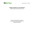
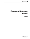
The following example illustrates the construction of a simple tessellated solid made from a
square base and six triangular walls. We first define the vertices
<define>
<position
<position
<position
<position
<position
<position
</define>
name="v1"
name="v2"
name="v3"
name="v4"
name="v5"
name="v6"
x="10" y="10" z="0" unit="m"/>
x="-10" y="10" z="0" unit="m"/>
x="-10" y="-10" z="0" unit="m"/>
x="10" y="-10" z="0" unit="m"/>
x="7" y="3" z="20" unit="m"/>
x="-3" y="7" z="5" unit="m"/>
and then we build the tessellated solid out of them
<tessellated name="pyramid">
<triangular vertex1="v1" vertex2="v2" vertex3="v6" type="ABSOLUTE"/>
<triangular vertex1="v2" vertex2="v3" vertex3="v6" type="ABSOLUTE"/>
<triangular vertex1="v3" vertex2="v4" vertex3="v5" type="ABSOLUTE"/>
<triangular vertex1="v4" vertex2="v1" vertex3="v5" type="ABSOLUTE"/>
<triangular vertex1="v1" vertex2="v6" vertex3="v5" type="ABSOLUTE"/>
<triangular vertex1="v6" vertex2="v3" vertex3="v5" type="ABSOLUTE"/>
<quadrangular vertex1="v4" vertex2="v3" vertex3="v2" vertex4="v1"
</tessellated>
Page 26 of 50
type="ABSOLUTE"/>
Figure: graphical representation of the tessellated solid as described in the example.
3.4.27
Tetrahedron
NB: supported only by Geant4
The tetrahedron solid in GDML is defined by specifying the coordinates of the four vertices.
In order for the solid not to be degenerated, the four points must not lie on the same surface.
The tet solid element contains the standard name attribute and four attributes being
references to the vertices namely vertex1, vertex2, vertex3 and vertex4. These
vertices are standard position elements which must be defined beforehand within the
define part.
The following example illustrates the construction of the tetrahedron.
<define>
<position
<position
<position
<position
</define>
name="v1"
name="v2"
name="v3"
name="v4"
x="10" y="10" z="0"/>
x="-10" y="10" z="0"/>
x="-10" y="-10" z="0"/>
x="0" y="0" z="10"/>
<tet name="halfpyramid" vertex1="v1" vertex2="v2" vertex3="v3" vertex4="v4"/>
Page 27 of 50
3.4.28
Using loops for solids
Suppose you want to define a set of solids with the same shape but with dimensions varying
according to a particular function. In this case loops are very useful, because the avoid
repetition of solids definitions. For a more detailed discussion on loops please refer to
Section 3.5.1. The following example shows you how to use a loop to define a set (10) of
boxes with different dimensions. Without a loop you would write the following code:
<box
<box
<box
<box
<box
<box
<box
<box
<box
<box
name=“box0”
name=“box1”
name=“box2”
name=“box3”
name=“box4”
name=“box5”
name=“box6”
name=“box7”
name=“box8”
name=“box9”
x=“1”
x=“4”
x=“7”
x=“10”
x=“13”
x=“16”
x=“19”
x=“22”
x=“25”
x=“28”
y=“5”
y=“4.5”
y=“4”
y=“3.5”
y=“3”
y=“2.5”
y=“2”
y=“1.5”
y=“1”
y=“0.5”
z=“20” />
z=“18” />
z=“16” />
z=“14” />
z=“12” />
z=“10” />
z=“8” />
z=“6” />
z=“4” />
z=“2” />
Using a loop you would only need four lines
<variable name=“x” value=“0”/>
declared in the “define” section and
<loop for=“x” to=“9” step=“1”>
<box name=“box” x=“1+(x*3)” y=“5-(x/2)” z=“20-(2*x)” />
</loop>
3.4.29
Boolean Solids
The GDML Boolean Solids can be described using following Boolean operations: union,
subtraction and intersection. As for Geant4 Boolean operations, the second solid is placed
with given position and rotation in the system coordinates of the first solid. The following
example illustrates the construction of Boolean solid using union operation:
<box name=“box_first” x=“1”
<box name=“box_second” x=“4”
y=“5”
z=“20” />
y=“4.5” z=“18” />
<union name= =“union” >
<first ref=“box_first” />
<second ref=“box_second”/>
<positionref ref=“union_position” />
<rotationref ref=“union_rotation” />
</union>
Another way to describe Union Solid is by using the MultiUnion construct, which offers
possibility to make union of many solids. The following example illustrates the construction
of a MultiUnion structure:
Page 28 of 50
<box name=“box_first” x=“1”
<box name=“box_second” x=“4”
y=“5”
z=“20” />
y=“4.5” z=“18” />
<multiUnion name= =“multiUnion” >
<multiUnionNode name-“node-1”>
<solid ref=“box_first” />
</multiUnionNode>
<multiUnionNode name=”node-2”>
<solid ref=“box_second” />
<positionref ref=“union_position” />
<rotationref ref=“union_rotation” />
</multiUnionNode>
</multiUnion>
3.5 Structure
The structure section is where volumes in the geometry are defined. Volumes are
referenced to solids and materials defined earlier to form the shape and composition of that
volume. This volume is then a logical volume. Volumes can be placed within this logical
volume; these volumes are called physical volumes. They can be positioned and rotated
how you wish within the logical volume. An example of the GDML for this is below:
<volume name="World">
<materialref ref="Air"/>
<solidref ref="WorldBox"/>
<physvol>
<volumeref ref="vol0"/>
<positionref ref="center"/>
<rotationref ref="identity"/>
</physvol>
</volume>
Page 29 of 50
3.5.1 Loops
Loops can be used to avoid tedious repetitions of definitions. To use a loop you need to
define a variable first (section 3.2.1). Suppose you defined a variable x with 0 initial value:
<variable name=“x” value=“0”/>
then, you can use it inside a loop statement:
<loop for=“x” to=“8” step=“2”>
…
</loop>
The code within the loop tags will we executed 5 times in this case, because the variable x
starting from the initial value of 0 (as in its definition) will be increased by 2 (according to the
step value) for each loop until it reaches the value of 8 (as stated in the to attribute).
Loops are very useful to access elements of matrices (see section 3.2.2); for example:
<variable name=“i” value=“1”/>
<matrix name=“m” coldim=“3” values=“ 0.4
8.5
34.6
<loop for=“i” to=“3” step=“1”>
… m[1,i] …
</loop>
9
7
7
126
21
9” />
We are able to access the three elements of the first row of the matrix, i.e. 0.4, 9 and 126.
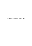
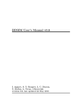
Loops can be used when defining solids, logical volumes and physical volumes; let’s see
how this is done in practice. Suppose we want to create the following structure:
Page 30 of 50
We need to write the code for 5 boxes, 5 logical volumes that refer to the boxes and 5
physical volumes that refer to the 5 logical volumes! The code would be the following:
<solids>
<box name=“box1” x=“10” y=“5” z=“5” />
<box name=“box2” x=“9” y=“4.5” z=“4” />
<box name=“box3” x=“8” y=“4” z=“3.2” />
<box name=“box4” x=“7” y=“3.5” z=“2.56” />
<box name=“box5” x=“6” y=“3” z=“2.048” />
</solids>
<structure>
<volume name=“volbox1”>
<solidref ref=“box1” />
<materialref ref=“iron” />
</volume>
<volume name=“volbox2”>
<solidref ref=“box2” />
<materialref ref=“iron” />
</volume>
<volume name=“volbox3”>
<solidref ref=“box3” />
<materialref ref=“iron” />
</volume>
<volume name=“volbox4”>
<solidref ref=“box4” />
<materialref ref=“iron” />
</volume>
<volume name=“volbox5”>
<solidref ref=“box5” />
<materialref ref=“iron” />
</volume>
<volume name=“world”>
...
<physvol>
<volumeref ref=“volbox1” />
<position x=“5” y=“0” z=“40” />
</physvol>
<physvol>
<volumeref ref=“volbox2” />
<position x=“5” y=“2” z=“38” />
</physvol>
<physvol>
<volumeref ref=“volbox3” />
<position x=“5” y=“3.5” z=“36” />
</physvol>
<physvol>
<volumeref ref=“volbox4” />
<position x=“5” y=“3.9” z=“34” />
</physvol>
<physvol>
<volumeref ref=“volbox5” />
<position x=“5” y=“4.15” z=“32” />
</physvol>
</volume>
</structure>
Page 31 of 50
Of course this is always possible; but using the loop tags (and combining them properly
with matrices), you would have the same result with fewer code lines and less complexity.
Here’s the equivalent code using the loop and matrix tags:
<define>
<matrix name=“m” coldim=“5” values=“0 2 3.5 3.9 4.15
5 4 3.2 2.56 2.048” />
<variable name=“x” value=“1” />
<variable name=“x1” value=“0” />
<variable name=“x2” value=“0” />
</define>
<solids>
<loop for=“x” to=“5” step=“1”>
<box name=“box” x=“10-(x-1)” y=“5-(x-1)/2” z=“m[2,x]” />
</loop>
</solids>
<structure>
<loop for=“x1” to=“4” step=“1”>
<volume name=“volbox”>
<solidref ref=“box” />
<materialref ref=“iron” />
</volume>
</loop>
<volume name=“world”>
...
<loop for=“x2” to=“8” step=“2”>
<physvol>
<volumeref ref=“volbox” />
<position x=“5” y=“m[1,x2/2+1]” z=“40-x2”/>
</physvol>
</loop>
</volume>
</structure>
In this example we only “looped” 5 times, but just think if we needed to loop 100 times or
more, the difference (in terms of code lines) between the two approaches would be
enormous.
Now two important rules you need to follow when using loops:
1) Always use a different (and properly initialized) variable for each loop tag (in our
example x, x1, x2 for the three loops).
2) When you use linked loop triples (loop triple = 3 loop tags, as we did in our example;
linked in the sense that we looped over a solid, then we looped over a logical volume
that referred to that solid, and finally we looped over a physical volume that referred
to that logical volume) you always have to be sure that the number of steps is the
same for every loop tag of that particular triple. In our example that number was 5:
from 1 to 5 in the first loop, from 0 to 4 in the second loop, and from 0 to 8 (but with a
step of 2) in the third loop.
3.5.2 Replicated Volumes
NB: supported only by Geant4
Replicated volumes in GDML correspond to Geant4 Replicas. Replica volumes are created
along the specific direction of one of Cartesian or Cylindrical Axis. The first replica is placed
at the given position and rotated according to given rotation and others are placed using
given distance. This repeated Volumes technique is available for volumes described by
Geant4 CSG Solids. The following example illustrates the construction of replica volumes
Page 32 of 50
along X Axis. An example ‘replicated.gdml’ can be found in the
$G4INSTALL/examples/extended/persistency/gdml/G01 girectory.
<solids >
…
<box name=“Mother_Cube” x=“800” y=“100” z=“100”/>
<box name=“Cube” x=“100” y=“100” z=“100”.>
</solids>
<structure>
…
<volume name=“lvCube”>
<solidref ref=“Cube” />
<materialref ref=“ALU” />
</volume>
<volume name=“lvReplica”>
<solidref ref=“Mother_Cube” />
<materialref ref=“AIR” />
<replicavol number=“8”>
<volumeref ref=“lvCube” />
<replicate_along_axis>
<direction x=“1” />
<width value=“100” unit=“mm” />
<offset value=“0”
unit=“mm” />
</replicate_along_axis>
</replicavol>
</volume>
</structure>
…
3.5.3 Parameterised Volumes
NB: supported only by Geant4
Parameterised volumes in GDML correspond to the parameterised physical volumes in
Geant4 with the difference that in GDML only parameterisation of dimension and placement
is supported.
Parameterisation of type of solid or its material is not supported by current implementation;
however it can be implemented as possible extension to the GDML schema.
Parameterised volumes are repeated volumes in the case in which the multiple copies of a
volume can be different in size and position.
Examples of GDML files describing parameterised volumes are parameterized.gdml and
pTube.gdml located in the example G01 distributed with Geant4.
The following example illustrates the construction of parameterised volumes:
<solids >
…
<box name=“tracker” x=“4800” y=“4800” z=“4800”/>
<box name=“chamber” x=“2000” y=“2000” z=“2000”.>
</solids>
<structure>
…
<volume name=“Chamber”>
<solidref ref=“chamber” />
<materialref ref=“XenonGas” />
Page 33 of 50
</volume>
<volume name=“Tracker”>
<solidref ref=“tracker” />
<materialref ref=“Air” />
<paramvol ncopies=“2”>
<volumeref ref=“Chamber”/>
<parameterised_position_size>
<parameters number=“1”>
<position name=“positionCopy1” x=“0” y=“0” z=“-1500”/>
<box_dimensions x=“240” y=“240” z=“100”/>
</parameters>
<parameters number=“2”>
<position name=“positionCopy2” x=“0” y=“0” z=“-700”/>
<box_dimensions x=“672” y=“672” z=“100”/>
</parameters>
</parameterised_position_size>
</paramvol>
</volume>
…
</structure>
…
For giving the dimensions of each parameterised solid in GDML a special syntax is used.
3.5.3.1.
Dimensions of Parameterised Box
The GDML dimensions of a parameterised box have the following form with 3 standard
dimensions: x, y and z. Example:
<box_dimensions x="30" y="30" z="30" lunit= "mm"/>
3.5.3.2.
Dimensions of Parameterised Tube
The GDML dimensions of a parameterised tube are given using :
InR
OutR
hz
StartPhi
DeltaPhi
inside radius of segment
outside radius of segment
z length of tube segment
starting phi position angle of segment
delta angle of segment
The following example illustrates its construction:
<tube_dimensions InR="30" OutR="60" hz="30" lunit= "mm"
StartPhi="60" DeltaPhi="30" aunit= "deg"/>
Page 34 of 50
3.5.3.3.
Dimensions of Parameterised Cone
The GDML dimensions of a parameterised cone are given using:
rmin1
rmax1
rmin2
rmax2
z
startphi
deltaphi
inside radius at base of cone
outside radius at base of cone
inside radius at top of cone
outside radius at top of cone
z length of cone
starting phi position of segment
delta angle of segment
The following example illustrates its construction:
<cone_dimensions rmin1="30" rmax1="60" rmin2="20" rmax2="60"
startphi="60" deltaphi="30" aunit= "deg"/>
3.5.3.4.
z="30" lunit= "mm"
Dimensions of Parameterised Orb
The GDML dimensions of a parameterised orb have the following form with 1 standard
dimension: r (radius). Example:
<orb_dimensions r="30" lunit= "mm"/>
3.5.3.5.
Dimensions of Parameterised Sphere
The GDML dimensions of a parameterised sphere are given using:
rmin
rmax
startphi
deltaphi
starttheta
deltatheta
inside radius
outside radius
starting phi position of segment
delta angle of segment
starting theta position of segment
delta theta angle of segment
The following example illustrates its construction:
<sphere_dimensions rmin="30" rmax="60" lunit= "mm"
starttheta="0" deltatheta="40"
startphi="60" deltaphi="30" aunit= "deg"/>
Page 35 of 50
3.5.3.6.
Dimensions of Parameterised Torus
The GDML dimensions of a parameterised torus are given using:
rmin
rmax
rtor
startphi
deltaphi
inside radius
outside radius
swept radius of torus
starting phi position of segment
delta angle of segment
The following example illustrates its construction:
<torus_dimensions rmin="30" rmax="60" rtor="160" lunit= "mm"
startphi="60" deltaphi="30" aunit= "deg"/>
3.5.3.7.
Dimensions of Parameterised Hype
The GDML dimensions of a parameterised hype are given using:
rmin
rmax
z
ihst
outst
inside radius
outside radius
length
inner stereo
outer stereo
The following example illustrates its construction:
<hype_dimensions rmin="30" rmax="60" z="160"
inst="3" outst="4" />
3.5.3.8.
lunit= "mm"
Dimensions of Parameterised Parallelepiped
The GDML dimensions of a parameterised parallelepiped are given using:
x
y
z
alpha
theta
phi
length of x
length of y
length of z
angle between x and z plane
polar angle of the line joining the centre of the faces –z&+z in z
azimuthal angle of the line joining the centre of the faces –z&+z in z
The following example illustrates its construction:
Page 36 of 50
<para_dimensions x="30" y="60" z= "60"
alpha="1" theta="1"
phi="1" lunit="mm" aunit= "rad"/>
3.5.3.9.
Dimensions of Parameterised Trapezoid
The GDML dimensions of a parameterised trapezoid are given using:
x1
x2
y1
y2
z
x length at - z
x length at +z
y length at - z
y length at +z
z length
The following example illustrates its construction:
<trd_dimensions x1="30" x2="60"
y1="20" y2="40"
z ="30" lunit= "mm"/>
3.5.3.10. Dimensions of Parameterised General Trapezoid
The GDML dimensions of a parameterised general trapezoid are given using:
x1
x2
x3
x4
alpha1
alpha2
theta
phi
y1
y2
z
length along x at side y=-y1 of the face at - z
length along x at side y=+y1 of the face at - z
length along x at side y=-y1 of the face at + z
length along x at side y=+y1 of the face at + z
angle with respect to the y axis from the centre of side at y=-y1
to centre of y=+y1 of the face at -z
angle with respect to the y axis from the centre of side at y=-y2
to centre of y=+y2 of the face at -z
polar angle of the line joining the centre of the faces –z&+z in z
azimuthal angle of the line joining the centre of the faces –z&+z in z
y length at - z
y length at +z
length along z axis
The following example illustrates its construction:
<trap_dimensions x1="30" x2="60" y1="20" y2="40" x3="30" x4="60" z ="30" lunit= "mm"
alpha1="30" alpha2="30" phi="30" theta="60" aunit="deg" />
Page 37 of 50
3.5.3.11. Dimensions of Parametrised Polycone
The GDML dimensions of a parameterised polycone are given using:
startPhi
openPhi
numRZ
zplane
start angle of the segment
angle of the segment
number of zplanes forming polycone
inner radius, outer radius and z coordinate of each plane
The following example illustrates its construction:
<polycone_dimensions startPhi="30" openPhi="60"
<zplane rmin="0" rmax="2" z="10" />
<zplane rmin="0" rmax="4" z="20" />
polycone_dimensions/>
numRZ="2" lunit= "mm" aunit="deg"
3.5.3.12. Dimensions of Parametrised Polyhedron
The GDML dimensions of a parameterised polyhedron (polyhedra) are given using:
startPhi
openPhi
numRZ
numSide
zplane
start angle of the segment
angle of the segment
number of zplanes forming polycone
number of sides
inner radius, outer radius and z coordinate of each plane
The following example illustrates its construction:
<polycone_dimensions startPhi="30" openPhi="60"
lunit= "mm" aunit="deg"
<zplane rmin="0" rmax="2" z="10" />
<zplane rmin="0" rmax="4" z="20" />
polycone_dimensions/>
numRZ="2" numSide="3"
3.5.3.13. Dimensions of Parametrised Ellipsoid
The GDML dimensions of a parameterised general tellipsoid are given using:
ax
by
cz
zcut1
zcut2
length of semi-axis in x direction
length of semi-axis in y direction
length of semi-axis in z direction
lower cut plane level at -z (solid lies above this plane)
upper cut plane level at +z (solid lies below this plane)
Page 38 of 50
The following example illustrates its construction:
<ellipsoid_dimensions ax="30" by="60"
cz="20" zcut1="-30"
zcut2="30"
lunit= "mm"/>
3.5.4 GDML Modules
GDML modules are GDML files used in the definition of (complex) geometries. They allow
an easier to understand view of big geometries as they split it into smaller (and therefore
more readable) pieces.
A GDML module is a normal GDML file and it is completely independent from all the other
modules (also from its mother module): it contains all the information (definitions, materials,
solids and volumes) it needs, to be fully defined. It defines a logical volume (which
corresponds to its world volume), which can be referenced by physical volumes of other
modules (which are called mother modules).
To include a GDML module (say child.gdml) in a mother module (say mother.gdml), in the
structure section of the mother module you should add a physical volume which points to
the child module, as in the following example:
- Instead of having one file:
// mother.gdml
<volume name="child">
<materialref ref="Alluminium"/>
<solidref ref="ChildBox"/>
</volume>
<volume name="mother">
<materialref ref="Iron"/>
<solidref ref="MotherBox"/>
<physvol>
<volumeref ref="child"/>
<positionref ref="center"/>
<rotationref ref="identity"/>
</physvol>
</volume>
- You can define child logical volume in a different GDML file, so you will have two files:
// mother.gdml
<volume name="mother">
<materialref ref="Iron"/>
<solidref ref="MotherBox"/>
<physvol>
<file name="child.gdml"/>
<positionref ref="center"/>
<rotationref ref="identity"/>
</physvol>
</volume>
// child.gdml
<volume name="child">
<materialref ref="Alluminium"/>
<solidref ref="ChildBox"/>
</volume>
Page 39 of 50
So in the general case instead of writing:
<volumeref ref="_logical_volume_"/>
You will need to write:
<file name="_logical_volume_.gdml"/>
And then define _logical_volume_ inside _logical_volume_.gdml.
In the example given above, the mother module will only contain the material Iron and the
solid MotherBox, while the child module will contain only the material Aluminium and the
solid ChildBox, thus enhancing readability and modularity.
Some advises:
- While it is not useful to have a module for every single volume of the geometry, it is good
to have one for each group of volumes that you would consider as a module in the real
world (see par. “Multiple GDML files”).
- Modules should have low coupling, i.e. they should be as independent as possible from
other modules (this improves reusability dramatically).
- Modules should have high cohesion, i.e. they should contain all (and only) the volumes
that contribute to the geometry of the corresponding real world modules (this improves
readability).
3.5.5 Volume Auxiliary Information
Volumes can have auxiliary information attached to them through GDML.
The auxiliary tags look like this:
<auxiliary auxtype=”SensDet” auxvalue=”veloSD1”/>
They have two attributes, auxtype and auxvalue, which are meant to specify what kind of
auxiliary information it is and what is its value. An additional, optional attribute auxunit is
also possible since version 3.1.2 of the schema; the new schema also allows for inserting
recursive auxiliary tags as part of a single auxiliary information block. It is important to stress
here that the GDML parser does not interpret in any way the auxiliary attributes. The
auxiliary attributes are stored in memory and available to the user once the parsing is done.
The auxiliary tags are placed within a volume like this:
<volume name="main">
<materialref ref="Iron"/>
<solidref ref="Box"/>
<physvol>
Page 40 of 50
<volumeref ref="world"/>
<positionref ref="center"/>
<rotationref ref="identity"/>
</physvol>
<auxiliary auxtype=”SensDet” auxvalue=”veloSD1”/>
<auxiliary auxtype=”Color” auxvalue=”blue”/>
</volume>
In Geant4, an additional GDML file example is auxiliary.gdml located in example G01
provided in the Geant4 distribution; the same example also provides a snippet of code in its
main() program showing how to retrieve the auxiliary information. Example G04 instead
shows how to define a sensitive detector associated to a logical volume, using the Auxiliary
Information field.
0 Auxiliary User Information
Since version 3.1.2 of the schema, it is possible to specify an -optional- auxiliary block
<userinfo> ... </userinfo>, after the <structure> ... </structure> block, where a
generic list of auxiliary tags can be included to describe specific features of a model, which
are then properly treated by the client code. Here is an example on how to represent
geometrical regions with energy cuts associated to logical volumes in Geant4:
<userinfo>
<auxiliary auxtype=”Region” auxvalue=”DefaultRegionForTheWorld”>
<auxiliary auxtype=”volume” auxvalue=”World”/>
<auxiliary auxtype=”gamcut” auxunit=”mm” auxvalue=”0.7”/>
<auxiliary auxtype=”ecut” auxunit=”mm” auxvalue=”0.7”/>
<auxiliary auxtype=”poscut” auxunit=”mm” auxvalue=”0.7”/>
<auxiliary auxtype=”pcut” auxunit=”mm” auxvalue=”0.7”/>
</auxiliary>
<auxiliary auxtype=”Region” auxvalue=”CalorA”>
<auxiliary auxtype=”volume” auxvalue=”CalorA”/>
<auxiliary auxtype=”gamcut” auxunit=”mm” auxvalue=”0.2”/>
<auxiliary auxtype=”ecut” auxunit=”mm” auxvalue=”0.2”/>
<auxiliary auxtype=”poscut” auxunit=”mm” auxvalue=”0.2”/>
<auxiliary auxtype=”pcut” auxunit=”mm” auxvalue=”0.2”/>
</auxiliary>
<auxiliary auxtype=”Region” auxvalue=”CalorB”>
:
</auxiliary>
:
</userinfo>
Page 41 of 50
3.6 Setup
The top volume of the geometry needs to be specified. This is done using the setup section.
The following GDML is the generic and most common for the setup section.
<setup name="Test1" version="1.0">
<world ref="World"/>
</setup>
The only part you should need to change is the world ref name to the volume name of the
top volume of your geometry. Only one setup is defined here, however it is possible define
multiple geometry setups choosing different volumes as world volumes from all the already
defined volumes.
Page 42 of 50
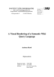
GDML file example
XML Declaration
GDML Namespace
XML Schema Instance
Namespace
GDML Schema Location
Declaration of constants,
positions, rotations, scalings,
variables and matrices
Definition of elements,
materials, isotopes etc. Only
materials can be referenced
to volumes
Simple material defined using
fractions of elements defined
higher up.
All solids to be used inside
the geometry defined here
All volumes declared in the
structure section.
World volume is declared
Physical Volumes placed
inside a Logical Volume with
a specified position, rotation
and scale
The top volume of the
geometry is specified
<?xml version="1.0" encoding="UTF-8" ?>
<gdml xmlns:gdml="http://cern.ch/2001/Schemas/GDML"
xmlns:xsi="http://www.w3.org/2001/XMLSchema-instance"
xsi:noNamespaceSchemaLocation="schema/gdml.xsd" >
<define>
<constant name="const1" value="100" />
<position name="pos1" unit="mm" x="0" y="0" z="0" />
<rotation name="rot1" unit="deg" x="const1" y="0" z="0" />
<scale name=”scl1” x=”-1” y=”+1” z=”+1”/>
</define>
<materials>
<element Z="7" formula="N" name="Nitrogen" >
<atom value="14.01" />
</element>
<element Z="8" formula="O" name="Oxygen" >
<atom value="16" />
</element>
<material formula=" " name="Air" >
<D value="0.00128" />
<fraction n="0.7" ref="Nitrogen" />
<fraction n="0.3" ref="Oxygen" />
</material>
</materials>
<solids>
<box aunit="radian" lunit="mm" name="world" x="10000" y="10000" z="10000" />
<box aunit="radian" lunit="mm" name="det” x="2000" y="2000" z="2000" />
</solids>
<structure>
<volume name="Detector" >
<materialref ref="Air" />
<solidref ref="det" />
</volume>
<volume name="World" >
<materialref ref="Air" />
<solidref ref="world" />
<physvol>
<volumeref ref="Detector" />
<positionref ref="pos1" />
<rotationref ref="rot1" />
<scaleref ref=”scl1” />
</physvol>
</volume>
</structure>
<setup name="Default" version="1.0" >
<world ref="World" />
</setup>
</gdml>
Page 43 of 50
4. Importing and exporting GDML files
4.1 GDML Reading
4.1.1 Importing GDML files into Geant4 Geometry
GDML files can be directly imported into Geant4 geometry, using the GDML plug-in facility
in your Geant4 application. Generally you will want to put the following lines into your
DetectorCostruction class:
- In the class constructor (as far as the initializations are concerned – step 2)
- In the Construct method (steps 3 and 4)
This can be done in four steps:
1) Include the necessary header files
#include “G4GDMLParser.hh”
2) Declare and initialize properly the parser
G4GDMLParser parser;
source_file.gdml will be your GDML source file, in case of multiple GDML files (modules)
you should put the main GDML file there (the main mother module).
3) Run the parser
parser.Read("source_file.gdml");
If solids or other entities with the same name are found in different modules, a warning
message is generated. Usually this happens when different GDML modules define the same
logical volume. This is not a problem, but it may suggest that the input GDML modules have
a low cohesion, therefore it maybe useful to review the way you have organized your
geometry. All names for solids, volumes and other entities are by default stripped of possible
strings concatenating their logical address in hexadecimal format; it is possible to disable
the name stripping by calling SetStripFlag(false)available from the parser, before
reading.
By default, when the parser reads a GDML file, comparison with the GDML Schema (from
GDML Schema Location) is made. It is possible to switch off this comparison by setting to
‘false’ second optional parameter in the Read:
parser.Read("source_file.gdml", false);
4) Get the World volume
G4VphysicalVolume* W = parser.GetWorldVolume(); //world volume
W->GetLogicalVolume()->SetVisAttributes(G4VisAttributes::Invisible);
Page 44 of 50
The second line is optional, but commonly used, because you generally don’t want to be
able to see the World volume.
4.2 GDML Writing
4.2.1 Exporting Geant4 Geometry
Geant4 geometry can be exported into GDML files. To do so you should do the following:
1) Include the Geant4 header file of the parser
#include “G4GDMLParser.hh”
2) Get the world volume from the geometry
G4VphysicalVolume* W = G4TransportationManager::
GetTransportationManager()->GetNavigatorForTracking()
->GetWorldVolume();
3) Instantiate the parser and write to file
G4GDMLParser parser;
parser.Write(“output.gdml”, W, true, "path_to_GDML_schema");
The last parameter is optional and refers to the GDML Schema path, it is very important to
set this right in order to allow for comparison with the Schema while reading the file back to
Geant4; the path can either be an absolute directory path relative to the system (schema
location local to that system) or an URL to the Schema. By default the schema location
points to the latest version of the GDML schema located in the GDML web site.
There exists also an optional third parameter, which is a Boolean value set by default to
TRUE. This parameter tells how you would like the names of volumes (as well as of solids,
materials and all entities) to be formatted in your output GDML file:
true (default) – The names will be concatenated with their logical address in hexadecimal
format. This is to avoid name duplication in the GDML output; in fact Geant4 allows different
volumes (as well as materials and solids) with the same name. When you will read the
GDML output file back into Geant4 the address part will be stripped off and you will have the
original names. This is almost always safe.
false – The names will NOT be concatenated with anything. So the names in the output file
will correspond exactly to the ones you have in Geant4. This is the prettiest format although
you have to be REALLY sure that you don’t have name duplication inside Geant4, otherwise
this will generate a GDML output with duplicated names, which will be unreadable by any
parser of course.
Page 45 of 50
4) Methods for dumping the geometry
There are three ways of doing this:
a) parser.Write("output.gdml", W);
Dumps all the geometry in a single GDML output file.
b) parser.AddModule(physvol);
Dumps the geometry modularizing the output. The generated module will include the
geometry tree starting from the physical-volume pointer physvol.
c) parser.AddModule(depth);
Dumps the geometry modularizing the output. The parameter in input is an integer
indicating the depth in the geometry levels from where you wish to start modularization. Any
new sub-tree at that depth level will become a module stored in a different GDML file; the
main tree binding all modules will include the geometry from the world volume down to that
specified level and will be stored in a separate GDML file.
4.2.2 Exporting ST-Viewer CAD Geometry
ST-Viewer is an interactive tool for viewing 3D CAD information. ST-Viewer includes
functions to display and relate product identification information, assembly structure
information and 3D geometry information. ST-Viewer implements the ISO STEP standard
for product model data. ST-Viewer works with a very large range of CAD, CAM, CAE and
PDM systems. A list of systems that have been tested with the ST-Viewer can be found at:
http://www.steptools.com.
ST-Viewer uses intermediate files to store CAD geometry and structure information. These
files (with .geom and .tree extensions respectively) use an internal format that can be
parsed and translated into GDML format using the functionalities provided by the Geant4
GDML plug-in.
The geometry of the solids is defined by means of triangular facets, i.e. every solid in the
.geom files is a tessellated solid made of only triangular facets. Therefore the GDML output
will be a collection of tessellated solids where each solid has its own set of facets that are in
turn defined by a set of three vertices. The vertices are named vectors of three values (x,y
and z coordinates) and are defined in the beginning of the GDML file. The facets within a
tessellated solid contain references to the names (not the values) of the three vertices they
are made of (for more information on how a tessellated solid is defined in GDML please
refer to the GDML Solids Schema : solids.xsd).
Of course multiple facets may share a common vertex, therefore in their definition there will
be a reference to the same vertex name. Again, the actual values of the vertices’ vectors are
stored in the first part (the one enclosed by the <define> and </define> tags) of the
GDML file.
In order to use the parser in your own application you need to
Page 46 of 50
1) Include the Geant4 parser header:
#include "G4GDMLParser.hh"
2) Instantiate a Geant4 parser object:
G4GDMLParser parser;
3) Call the parse method:
G4LogicalVolume* STW = parser.ParseST("filename", med_mat, geo_mat);
This method takes three parameters: the first one is a string which specifies the name
without file extension for the .geom and .tree files (assumed to have the same names and
be located in the current directory). It returns a pointer of a generated mother volume with
'med_mat' material pointer associated, including the imported tessellated geometry with
'geom_mat' material pointer associated.
Common vertices will not be repeated in the define section, i.e. facets sharing the same
vertex will refer to the same vertex name defined at the beginning of the GDML file. In this
case there will not be any two vertices with the same coordinates.
During a test, a input .geom file of 9.5 MB could be saved in a GDML output file of 10.5 MB;
the same input file would have become a 33 MB GDML output file, with repetition of
common vertices.
4) Call the dump method:
parser.Write("output.gdml", STW_phys);
The same method of the parser for writing the GDML output file can be used, by passing the
placed physical volume pointer of such geometry.
The result is a GDML file corresponding to the .geom and .tree files previously taken as
input.
5. User extensions to GDML using Geant4
The GDML syntax is defined in an XML schema. Inside the schema are all the definitions of
the tags and the rules associated to those tags. The GDML schema can be extended, as
XML is a fully extendable mark-up language. This section will discuss how to add custom
elements to GDML. This could be useful if certain information is required to be contained in
the GDML file for an application of GDML. The extension can be defined as such to contain
a new tag and values within whichever chosen part of the GDML file. It may be the case that
within the binding to GDML being used, there are methods already in place for information
not supported by the GDML schema, in which case the user extension facility will help
implementing that.
An example of a user extension is implemented in Geant4 and can be found in the directory
geant4/examples/persistency/gdml/G03. This example will be used as a point of
reference throughout this section.
Page 47 of 50
The Schema
The first step in extending GDML is to redefine the GDML schema. It needs to include the
custom elements of the extension. The extension is done in a separate schema file that
imports the original schema as opposed to adding new parts to the old one. The schema for
example G03 is found in a subdirectory of the example:
SimpleExtensionSchema/SimpleExtension.xsd
The original main GDML schema is imported from its local, relative location within your
GDML directory. The new schema file normally will need to contain two main parts:
5.1 A ‘redefine’ element
This element uses the extension schema to modify existing GDML elements by adding
additional content. This is called by this line, which gives the location of the schema to
redefine:
<xs:redefine schemaLocation="schema/gdml.xsd">
In most cases, the extension will consist in defining new objects (like color) to a volume etc.
In such case, the redefine needs to add a ReferenceType to the base it needs to be added
to:
<xs:extension base="VolumeType">
<xs:sequence>
<xs:element minOccurs="0" maxOccurs="1" name="colourref" type="ReferenceType"/>
</xs:sequence>
</xs:extension>
5.2 New Elements
The new schema will need to define the new ‘element’ that the ReferenceType will be
referencing to. In the example of adding a 'color' reference to a volume, the element color
will need to be defined.
When elements are defined, attributes of that element are defined within it, but if tags within
the element contain more than one attribute, a type needs to be defined, and then
referenced to. This is implemented in the G03 schema file.
All the new elements can't be contained inside the <gdml> tag as they are not part of the
original schema, there needs to be a new container defined that contains the new elements
AND replaces the original <gdml> tag; we call it here, <gdml_simple_extension>.
A new special tag, <extension>, is used to include all new tags to be considered as
extension to the original GDML schema; in our example, we have only one tag, <color>,
which is part of the extension. This is shown below:
<xs:element name="gdml_simple_extension">
<xs:annotation>
<xs:documentation>
Page 48 of 50
New container for new element and gdml.
</xs:documentation>
</xs:annotation>
<xs:complexType>
<xs:sequence>
<xs:element ref="extension" minOccurs="0" maxOccurs="1"/>
<xs:element ref="gdml" minOccurs="1"/>
</xs:sequence>
</xs:complexType>
</xs:element>
This then means that a GDML file now takes the following structure based on the above:
<gdml_simple_extension xmlns:gdml_simple_extension= "http://www.example.org"
xmlns:xs="http://www.w3.org/2001/XMLSchema-instance"
xs:noNamespaceSchemaLocation="./SimpleExtensionSchema/SimpleExtension.xsd">
<extension>
<color name="aColor" R="1.0" G="0.0" B="0.0" A="1.0" />
</extension>
<structure>
<volume>
<materialref ref="someMaterial"/>
<solidref ref="someSolid"/>
<colorref ref="aColor"/> <!—- new reference type -->
</volume>
</structure>
</gdml_simple_extension>
In any GDML file you wish to use your ‘extended schema’ in, you will need to change the
Namespace GDML Schema Location to your extended schema file and replace the original
schema. The new schema location must be relative to the location of the GDML file in
question. This will then import your new additions as well as the original GDML schema, as
shown above.
Customised Reader
Once the GDML schema has been extended as wished, the application making use of the
extended GDML, needs to provide the necessary instruments in order to properly handle the
extensions. This is done by implementing a specialized 'reader' class, whose instance will
replace the standard reader inside the G4GDMLParser class in Geant4. The new class must
inherit from G4GDMLStructureRead and override in this case two methods:
void ExtensionRead(const xercesc::DOMElement* const element);
void VolumeRead(const xercesc::DOMElement* const element);
The former will have to handle the top level parsing of the new tags (in our case, <color>),
while the latter will have to properly bound the new reference-type (<colorref>) to the
volume, such that the new tag can be assigned as attribute to the volume entity.
In our example, the class ColorReader implements such required functionality.
An instance of the reader must be dynamically created in the DetectorConstruction class
and provided through pointer argument to the G4GDMLParser instance to be created as
usual for importing GDML files in Geant4.
Page 49 of 50
Try it...
To run the example application you simply need to build it, using the standard procedure as
for any Geant4 application. Then from the G03 directory, you can run the example using this
command:
read_ext [filename.gdml]
The default file is color_extension.gdml, which defines a single colored box in the world
volume.
Page 50 of 50