1
User’s Guide
EasyCoder
501 XP
Bar Code Label
Printer
Information in this manual is subject to change without prior notice and does not represent a
commitment on the part of Intermec Printer AB.
© Copyright Intermec Printer AB, 2002. All rights reserved. Published in Sweden.
EasyCoder, EasyLAN, Fingerprint, and LabelShop are registered trademarks of Intermec Technologies Corp. The word Intermec, the Intermec logo, InterDriver, PrintSet, and Duratherm are
trademarks of Intermec Technologies Corp.
Centronics is a registered trademark of Genicom Corporation.
Kimdura is a registered trademark of Kimberly Clark.
Microsoft is a registered trademark of Microsoft Corporation.
Torx is a registered trademark of Camcar Division of Textron Inc.
TrueDoc is a registered trademark of Bitstream, Inc.
TrueType is a trademark of Apple Computer Inc.
Unicode is a trademark of Unicode Inc.
Windows is a trademark of Microsoft Corporation.
Preface
Contents
Preface
Table of Contents .........................................................................1
FCC Notice..................................................................................4
DOC Notice.................................................................................4
Declaration of Conformity (CE)..................................................5
1. Introduction
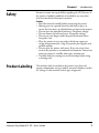
EasyCoder 501 XP .......................................................................6
Safety Requirements .....................................................................7
Product Labeling ..........................................................................7
2. Installation
Unpacking ....................................................................................8
Front View....................................................................................9
Rear View ...................................................................................10
Media Compartment .................................................................11
Print Unit....................................................................................12
Connections ...............................................................................13
• Power ...................................................................................13
• Computer ............................................................................13
Controls and Indicators..............................................................14
• Control Lamps.....................................................................14
• Display .................................................................................14
• Keyboard..............................................................................14
• Beeper ..................................................................................15
3. Starting Up
Startup Files ................................................................................16
Memory Cards............................................................................17
Switching On the Printer ...........................................................18
Display Messages at Startup .......................................................18
4. Media Load
Tear-Off (Straight-through) .......................................................19
Cut-Off.......................................................................................23
Peel-Off (Self-strip).....................................................................28
Internal Batch Takeup ................................................................33
External Supply (Fanfold)...........................................................38
5. Thermal Transfer Printing
Ribbon Load...............................................................................40
6. Setting Up the Printer
Description.................................................................................44
Default Setup..............................................................................45
Intermec EasyCoder 501 XP – User’s Guide
1
Preface
Contents, cont.
6. Setting Up the Printer, cont.
Setup Parameters: .......................................................................46
• Serial Communication:........................................................46
- Baud Rate ..........................................................................46
- Character Length...............................................................47
- Parity..................................................................................47
- Stop Bits.............................................................................47
- Flow Control .....................................................................47
- New Line ...........................................................................48
- Receive Buffer ....................................................................48
- Transmit Buffer..................................................................48
• Feedadjust: ...........................................................................49
- Startadjust ..........................................................................49
- Stopadjust ..........................................................................49
- Recommended Feed Adjustments.....................................49
• Media:..................................................................................50
- Media Size..........................................................................50
- Media Type ........................................................................52
- Paper Type..........................................................................53
- Contrast .............................................................................57
- Testfeed ..............................................................................57
• Print Defines:.......................................................................57
- Head Resistance.................................................................57
- Testprint.............................................................................57
- Print Speed.........................................................................59
7. Setup Mode
Entering the Setup Mode at Installation....................................60
Navigating in Setup Mode .........................................................61
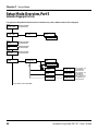
Setup Mode Overviews ..............................................................62
8. Intermec Shell Startup Program Introduction ...............................................................................67
Starting with Intermec Shell.......................................................68
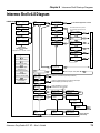
Intermec Shell v4.8 Diagram .....................................................71
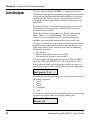
Line Analyzer..............................................................................72
9. Options
2
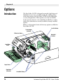
Introduction ...............................................................................74
Liner/Batch Takeup Kit..............................................................75
Paper Cutter................................................................................75
Fan Fold Guides .........................................................................76
Media Roll Retainer....................................................................76
Edge Guide.................................................................................76
3-inch Adapter............................................................................76
Intermec EasyCoder 501 XP – User’s Guide
Preface
Contents, cont.
9. Options, cont.
Label Taken Sensor.....................................................................76
Ribbon Low Sensor ....................................................................77
Interface Boards..........................................................................77
10. Troubleshooting
Troubleshooting List...................................................................78
11. Maintenance
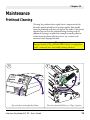
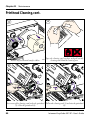
Printhead Cleaning.....................................................................79
External Cleaning .......................................................................82
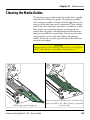
Cleaning the Label Stop Sensor Guides .....................................83
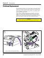
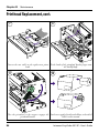
Printhead Replacement ..............................................................84
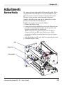
12. Adjustments
Narrow Media ............................................................................87
Printhead Pressure ......................................................................88
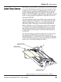
Label Stop Sensor .......................................................................89
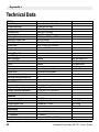
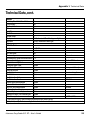
Appendix 1
Technical Data............................................................................90
Appendix 2
Media Specifications...................................................................92
• Direct Thermal Media.........................................................92
• Thermal Transfer Media ......................................................93
• Media Roll Size ....................................................................94
• Media...................................................................................95
• Thermal Transfer Ribbons.................................................100
Appendix 3
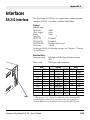
Interfaces...................................................................................101
• RS-232 Interface................................................................101
• Parallel Interface.................................................................102
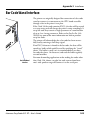
• Bar Code Wand Interface ..................................................103
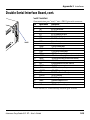
• Double Serial Interface Board (option) .............................104
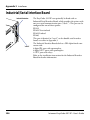
• Industrial/Serial Interface Board (option)..........................106
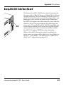
• EasyLAN 100i Interface Board (option) ...........................107
• Industrial Interface Board (option)....................................108
Intermec EasyCoder 501 XP – User’s Guide
3
Preface
FCC Notice (United States of America)
WARNING
This equipment generates, uses, and can radiate radio frequency energy and if not installed and
used in accordance with the instructions manual, may cause interference to radio communications.
It has been tested and found to comply with the limits for a Class A computing device pursuant
to Subpart J of Part 15 of FCC Rules, which are designed to provide reasonable protection against
such interference when operated in a commercial environment. Operation of this equipment in
a residential area is likely to cause interference in which case the user at his own expense will be
required to take whatever measures may be required to correct the interference.
DOC Notice (Canada)
Canadian Dept. of Communication
REGULATIONS COMPLIANCE (DOC-A)
This digital apparatus does not exceed the class A limits for radio noise emissions from a digital
apparatus as set out in the radio interference regulations of the Canadian Department of Communication.
Ministère des Communications du Canada
CONFORMITE DE REGLEMENTS (DOC-A)
Le présent appareil numérique n’émet pas de bruits radio-électriques dépassant les limites applicables
aux appareils numériques de classe A prescrites dans le règlement sur brouillage radioélectrique édicté
par le Ministère des Communications du Canada.
4
Intermec EasyCoder 501 XP – User’s Guide
Preface
Declaration of Conformity (CE)
We,
Intermec Printer AB
Idrottsvägen 10
Box 123
S-431 22 Mölndal
Sweden
declare under our sole responsibility1 that the product
EasyCoder 501 XP
to which this declaration relates is in conformity with the following standards
Electrical Safety: EN 60950
EMC Emissions: EN 50081-1:92
(EN 55022:94, EN 61000-3-2:95)
EMC Immunity: EN 50082-2:95
(EN 61000-4-2:95; EN 61000-4-3:96; ENV 50204:95;
EN 61000-4-4:95; EN 61000-4-6:96)
following the provisions of Directives
89/336/EEC and 73/23/EEC
Mölndal 1998-09-01
...................................................................
Mats Gunnarsson
President
1
/. Intermec assumes no responsibility regarding the CE Directive if the
printer is handled, modified, or installed in other manners than those described in
Intermec’s manuals.
Intermec EasyCoder 501 XP – User’s Guide
5
Chapter 1
Introduction
EasyCoder 501 XP
The EasyCoder 501 XP is a high-volume 4-inch thermal printer,
which provides an astounding print speed of up to 300 mm/sec
(12 inches/sec) at 300 dots per inch (dpi.) It also offers a large
number of useful features, such as:
• Flash memory SIMMs for firmware, fonts, bar codes, and
application programs
• Built-in memory card adapter
• Built-in Centronics and RS-232 interfaces
• Provision for extra interface boards
• Advanced ribbon-handling system to prevent ribbon wrinkling
• Built-in keyboard and display with backlight
The EasyCoder 501 XP works both as a direct thermal printer
and thermal transfer printer for tear-off (straight-through) operation. An automatic paper cutter is available as an option and can
be fitted by the user without any tools in a few seconds. There
is also an optional factory-installed liner takeup unit for peel-off
(self-strip) operation and internal takeup of printed batches of
labels.
The EasyCoder 501 XP supports the unique and flexible Intermec Fingerprint v7.61 programming language, which allows
the user to create custom-made application programs and label
layouts in a BASIC-like environment. It is also designed to
work with the Intermec Direct Protocol programming language
and with the Intermec InterDriver. The InterDriver allows you
to design labels using standard PC applications, for example
Microsoft Office.
The EasyCoder 501 XP supports 15 scaleable Unicode TrueType
and TrueDoc fonts as standard. Additional fonts can be downloaded into the printer’s Flash memory, or be plugged in using
a memory card. The Unicode standard allows the use of special
characters for various languages including non-Latin fonts, such
as Cyrillic, Chinese, Japanese, Korean, Hebrew, and similar.
6
Intermec EasyCoder 501 XP – User’s Guide
Chapter 1
Safety
Introduction
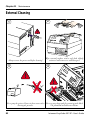
Intermec assumes no responsibility regarding the CE Directive if
the printer is handled, modified, or installed in any way other
than that described in Intermec’s manuals.
Caution
• Read this manual carefully before connecting the printer.
• Moving parts are exposed when the side door is open, so
ensure that the covers are closed before you operate the printer.
• Do not open the front/left-hand cover. Dangerous voltage!
• Do not remove the left-hand cover. Dangerous voltage!
• Do not put your fingers inside the print mechanism when
the power is on.
• Place the printer on an even surface which can support its
weight of approximately 13 kg (29 pounds) plus supplies and
possible options.
• Do not spray the printer with water. If you are using a hose
to clean the premises in an industrial environment, remove the
printer or protect it carefully from spray and moisture.
• Carefully read the warning text on the envelope before using
a cleaning card.
Product Labeling
The machine label is attached to the printer’s rear plate and
contains information on type, model, and serial number as well as
AC voltage. It also contains various signs of approval.
Intermec EasyCoder 501 XP – User’s Guide
7
Chapter 2
Installation
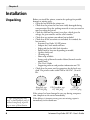
Unpacking
Before you install the printer, examine the package for possible
damage or missing parts:
• Open the box and lift the printer out.
• Check that the printer has not been visibly damaged during
transportation. Keep the packing materials in case you need to
move or reship the printer.
• Check the label on the printer’s rear plate, which gives the
voltage, the part number, and the serial number.
• Check that any options you ordered are included.
• Check that all the accessories are included. As standard, the
box contains:
- Intermec EasyCoder 501 XP printer
- Adapter for 3-inch media roll core
- Edge guide for the label slack absorber
- Power cord (at least one depending on model)
- Quality check card
- Cleaning card
- Short strip of labels1
- Starter pack of thermal transfer ribbon (thermal transfer
models only)1
- This User’s Guide
- Supporting software and product information on CD.
• Check that the power cord is appropriate for the local standard. The printer works within 100 to 240 VAC, 50 to 60
Hz.
European-type
230 VAC plug
US/Canadian-type
115 VAC plug
GB-type
230 VAC plug
If the printer has been damaged in any way during transportation, complain to the carrier immediately.
1
/. Type and quantity may
vary, or labels/ribbon may be
omitted completely, depending on area of distribution.
8
If the delivery is incorrect or any parts are missing, report it
immediately to the distributor.
Intermec EasyCoder 501 XP – User’s Guide
Chapter 2
Front View
Installation
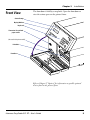
The front door is held by a snap-lock. Open the front door to
view the various parts on the printer’s front.
Control Lamps
Display Window
Keyboard
Connector for optional
paper cutter
(Not used in this printer model)
Print Unit
Front Door
Refer to Chapter 9 “Options” for information on possible optional
devices fitted on the printer’s front.
Intermec EasyCoder 501 XP – User’s Guide
9
Chapter 2
Installation
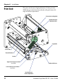
Rear View
The rear plate contains the On/Off switch, the AC power cord
receptacle, and various interface connectors and slots.
Provision for optional Interface Boards
Bar Code Wand Connector
On/Off Switch
Not used
AC Power Cord Receptacle
RS-232 Serial Interface Connector ("uart1:")
Upper External Media Intake
Centronics Parallel Interface
Memory Card Slot
Machine Label
Lower External Media Intake
10
Intermec EasyCoder 501 XP – User’s Guide
Chapter 2
Installation
Media Compartment
The media compartment becomes accessible when the right-hand
door is opened. The door is held by a magnetic lock and can be
opened 180°, or be removed completely by pushing it rearwards.
Ribbon Rewind Hub
Ribbon Supply Hub
Media Supply Hub
N
TIO
.
MatA
head
e
print
FOR
nce
validthis
portathe
ill in for
N IN
t im hed
I, w ally
BO
ific
greamatc using
UB
o offullyvise of
RIB
d byd spec
D su
re
ad
is als
pplie
care
N
ee
s
er
A ose engin
int I ha ongly
th are
is pr. UB e str .
AD
ad efor ing
in th
than
HEher rib
s
he
int
er
bons
T
lie
int
pr
th
, ot fer
supp e pr We ality
RIN
bons ns
dia of th er. h qu
TP
r rib l tra
hig
r meg lifeis print
AN
nsfe erma
th
re a
nsfe lon
RTma
l traUBI th
l traand aeds of ensu
y.
PO
er
erma s e ne lies to
y th arrant
IM
d th code
to thsupp
l an bar
of an w
-OFF
TEAR
d
ideided
ma ing
use thea
therprint d/prov
prov
Thee prin
ty ofty ofmmen ded/
th
en
quali
quali co
Ther the we re comm
fo per
I re
pa ly UB
on
Slack Absorber
Refer to Chapter 9 “Options” for information on possible optional
devices fitted inside the printer’s media compartment.
Intermec EasyCoder 501 XP – User’s Guide
11
Chapter 2
Installation
Print Unit
The print unit features a high-performance 12 dots-per-mm
(≈300 dots-per-inch) thermal printhead with quick-mount fittings to facilitate replacement.
Pressure Arm Locking Knob
Printhead Pressure
Adjustment Knob
Edge Guide
Pressure Arm
Thermal Printhead
Tear Bar
Upper Label Stop Sensor Guide
(removable)
Printhead Lift Lever
Lower Label Stop Sensor Guide
(removable)
Label Stop Sensor
Position Adjustment
12
Intermec EasyCoder 501 XP – User’s Guide
Chapter 2
Installation
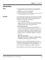
Connections
Power
1 Place the printer on a level surface near an AC outlet. You
should be able to easily access the printer to load media, to
load ribbon, and to remove the printout.
2 Check that the printer is switched off.
3 Connect the power cord to the receptacle on the rear plate and
to an electrical outlet (>90 to <264 VAC.)
Computer
The Easycoder 501 XP is fitted with one 36-pin female Centronics connector for the parallel interface port and a 25-pin D-style
subminiature (DB-25) male connector for the RS-232 serial
interface port (see Appendix 3, “Interfaces”).
• Centronics Parallel Interface
Use the parallel interface with the Intermec InterDriver (for
Windows) because it is faster than the serial interface. There is
no communication setup for the parallel interface.
• RS-232 Serial Interface
Use the serial interface with Intermec Direct Protocol or
Intermec Fingerprint programming language because you can
receive error messages from your printer (as opposed to the
parallel interface.) Before you can use the serial interface, you
may need to set up the communication parameters, such as
baud rate, parity etc. as described in Chapter 6, “Setting Up
the Printer.”
• Optional Interface Board
Several types are available (see Chapter 9, “Options.)” Refer
to Appendix 3 and the separate documentation delivered with
the boards for connection and setup instructions.
The printer can be set to scan all communication ports for
incoming data and automatically switch to that port. This facility
("auto:") can be selected in Intermec Shell (see Chapter 7)
or using the Intermec Fingerprint instruction SETSTDIO, see
Intermec Fingerprint v7.61, Programmer’s Reference Manual.
Switch off both PC and printer before connecting them together.
Intermec EasyCoder 501 XP – User’s Guide
13
Chapter 2
Installation
Controls and Indicators
The EasyCoder 501 XP has several ways of communicating
directly with its operator: three control lamps, a display window,
a membrane-switch keyboard with 23 programmable keys, and
a beeper.
Ready
Power
Error
EasyCoder
501 XP
F1
Shift
F2
F3
F4
F5
7
8
9
Pause
Setup
4
5
6
Feed
Enter
1
2
3
,
0
C
Pri nt
Control Lamps
The control lamps are colored LEDs (Light Emitting Diodes)
and are used for the following purposes:
• Power (green) indicates that the power is on.
• Ready (green) indicates that the printer is ready for use.
• Error (red) indicates that some kind of error has occurred.
If serial communication is used, an error message may be
returned to the host computer.
Display
The display window contains an LCD (Liquid Crystal Display)
with background illumination and two lines of text, each with 16
characters. It guides the operator through the setup and indicates
possible errors during printing.
The Intermec Fingerprint programming language and the
Intermec Direct Protocol allow custom-made messages to be
composed and displayed according to the requirements of the
application.
Keyboard
The keyboard is of membrane-switch type and has a self-adhesive
overlay that easily can be replaced for special applications. It
has 23 keys with hardcoded functions in the startup and setup
modes.
In application programs created using the Intermec Fingerprint
programming language, the keys can be assigned to various
functions. Since one key works as shift key, up to 44 different
key combinations are possible. An audible signal, which can be
turned off, acknowledges that a key has been pressed.
14
Intermec EasyCoder 501 XP – User’s Guide
Chapter 2
Installation
Controls and Indicators, cont.
Beeper
The beeper notifies the operator when an error has occurred
and acknowledges that a key has been pressed. The Intermec
Fingerprint programming language allows the key acknowledge
signal to be switched off. The frequency and duration of the
signal can be specified. Thus, it is possible create different signals
for different conditions or even to make the printer play simple
melodies!
Intermec EasyCoder 501 XP – User’s Guide
15
Chapter 3
Starting Up
Startup Files
When the printer is switched on, its behavior depends on the
existence of a startup file (autoexec.bat) in its memory. There
are two cases:
A The printer is only fitted with the Intermec Shell file-managing program, which allows the operator to choose between a
variety of applications and functions.
B In addition to Intermec Shell, the printer is also fitted with
a custom-made application program that is design to perform
a specific task, for example to print tickets, baggage tags, or
product labels for a certain company. Such a program may be
initiated by a startup file (autoexec.bat) stored in the printer’s
permanent memory or in a memory card.
There can be one startup file stored in each of three different
parts of the printer’s memory. If there are startup files stored in
more than one part, only one will be used with the following
priority:
1. An autoexec.bat file stored in a memory card, provided the
card was inserted in the printer before power up.
2. An autoexec.bat file stored in the read/write part of the
printer’s permanent memory (device "c:").
3. The pup.bat file (Intermec Shell) in the read-only part of the
printer’s permanent memory (device "rom:").
If you insert a memory card that contains a startup file before
you switch on the printer, this startup file will be used instead
of Intermec Shell.
16
Intermec EasyCoder 501 XP – User’s Guide
Chapter 3
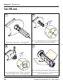
Memory Card
Starting Up
If you want to use a memory card, you must insert it into
the slot in the printer’s rear plate before you switch on the
power. The memory card can be an SRAM card complying with
the JEIDA-4 standard or a Flash Memory card from Intermec.
Maximum size in both cases is 64Mbit (8MB). There are three
types of Flash Memory cards:
• Font Cards provide additional fonts that can be used as long as
the card remains inserted in the printer.
• Font Install Cards permanently install additional fonts in
the printer, which can be used even after the card has been
removed.
• Firmware Cards automatically replace the printer’s firmware,
usually with an updated version.
Memory Card
e
Backsid
Important!
Always switch off the power before inserting or removing a memory
card! The manufacturer’s logotype should face right when viewing
the card as in the illustration above.
Intermec EasyCoder 501 XP – User’s Guide
17
Chapter 3 Starting Up
Switching On the Printer
Warning!
During startup, an optional
paper cutter will rotate to
home position. Always keep
the cutter closed when the
power is on.
Before switching on the printer, make the necessary connections,
insert any memory card you want to use, and check that the
printhead is engaged and the optional cutter is closed.
Switch on the power using the On/Off switch on the rear plate.
The “Power” control lamp on the front panel lights up when the
power is on. Wait for a few moments, while the printer loads
the program and runs some self-diagnostic tests. Then some kind
of message will appear in the display window, depending on the
startup file.
Display Messages at Startup
When the power is switched on, the printer is initialized. The
progress of the initialization is indicated by an increasing number
of colons on the lower line in the display:
Initializing
:::
The type of startup file running in the printer is indicated by
the message shown in the display window immediately after
initialization.
A. Intermec Shell Startup Program (standard printers)
ENTER=SHELL
5 sec.
v.4.8
4 sec.
v.4.8
3 sec.
v.4.8
2 sec.
v.4.8
1 sec.
v.4.8
Refer to Chapter 8 for more information on Intermec Shell. The
digits in the lower right corner of the display indicate the version
of Intermec Shell.
B. Custom-Made Application Program (non-standard printers)
Any other display messages than those illustrated above indicates
that the printer is running some custom-made, non-standard
application program, or that some error has occurred.
18
Intermec EasyCoder 501 XP – User’s Guide
Chapter 4
Media Load
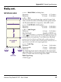
Tear-Off (Straight-through)
The EasyCoder 501 XP can print on labels, tickets, tags, and
continuous stock in various forms. This section describes the case
when the media is torn off manually against the printer’s tear bar.
This method is also known as “straight-through printing.”
Use the <Feed> key (see figure #11) when loading the same
type of media. When switching to a new type of media, or if
the printer does not feed out the media properly, simultaneously
press the <Shift> and <Feed> keys to perform a “testfeed.”
Tear-off can be used for:
• Non-adhesive continuous stock
• Self-adhesive continuous stock with liner
• Self-adhesive labels with liner
• Tickets with gaps, with or without perforations
• Tickets with black marks, with or without perforations
An optional label taken sensor can hold the printing of the next
copy in the batch until the present copy has been removed, see
Chapter 9, “Options.”
2
1
Open the front and right-hand doors.
Intermec EasyCoder 501 XP – User’s Guide
Turn the printhead lift lever to ”Open” position.
19
Chapter 4
Media Load
Tear-Off, cont.
3
4a
mm
38-40 )
(1.5"
Remove any core from the media supply hub.
4b
Fit a new roll of media on the media supply hub and
push the roll inwards as far as it will go.
5
m
76 m
)
"
(3
Route the media underneath the slack absorber and
In case of media roll with a 76 mm (3-inch) core, forward towards the print unit. The slack absorber
first fit an adapter on the media supply hub.
can be rotated for better access.
20
Intermec EasyCoder 501 XP – User’s Guide
Chapter 4
Media Load
Tear-Off, cont.
6
7
Route the media through the print unit and push it
inwards as far as it will go.
8
Turn the printhead lift lever to “Closed” position.
Intermec EasyCoder 501 XP – User’s Guide
This diagram shows the media path.
9
Adjust the position of the green edge guide so the
media is guided with a minimum of play.
21
Chapter 4
Media Load
Tear-Off, cont.
10
11
Feed
Close the front and right-hand doors.
Press the Feed key to advance the media and adjust
the media feed.
12
To tear off the media, grab the outer edge and pull
downwards.
22
Intermec EasyCoder 501 XP – User’s Guide
Chapter 4
Cut-Off
Media Load
The EasyCoder 501 XP can print on labels, tickets, tags, and
continuous stock in various forms. This chapter describes the case
when the media is automatically cut off after printing using an
optional paper cutter.
Use the <Feed> key (see figure #14) when loading the same type
of media as before. When switching to a new type of media, or if
the printer does not feed out the media properly, simultaneously
press the <Shift> and <Feed> keys to perform a “testfeed.”
Cut-off can be used for:
• Non-adhesive continuous stock
• Self-adhesive labels with liner
Note that the cutter must not cut through the labels–only the
liner–or the adhesive will stick to the blades and render the cutter
inoperable or even damage the cutter’s motor!
• Tickets with gaps without perforations
• Tickets with marks without perforations
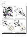
WARNING!
The rotating cutting blade can be accidently activated when the
cutter is opened. To avoid any risk of injury to fingers, always
switch off the power before loading media and/or ribbon in a
cutter-equipped printer.
1
Switch off the power using the On/Off switch on
the printer’s rear plate.
Intermec EasyCoder 501 XP – User’s Guide
2
Open the cutter unit and the right-hand door.
23
Chapter 4
Media Load
Cut-Off, cont.
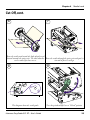
4
3
Turn the printhead lift lever to ”Open” position.
Remove any core from the media supply hub.
5b
5a
mm
38-40 )
(1.5"
m
76 m
)
"
(3
Fit a new roll of media on the media supply hub and In case of media roll with a 76 mm (3-inch) core,
push the roll inwards as far as it will go.
first fit an adapter on the media supply hub.
24
Intermec EasyCoder 501 XP – User’s Guide
Chapter 4
Media Load
Cut-Off, cont.
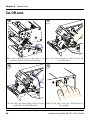
6
7
Route the media underneath the slack absorber and
forward towards the print unit. The slack absorber Route the media through the print unit and push it
can be rotated for better access.
inwards as far as it will go.
8
9
This diagram shows the media path.
Intermec EasyCoder 501 XP – User’s Guide
Turn the printhead lift lever to “Closed” position.
25
Chapter 4
Media Load
Cut-Off, cont.
10
11
TEAR
-OFF
T PR
RTAN
PO
IM
er
nsf th
I
l tra
rma . UB
the rranty
th
l and ba
of any wa
ead
rma tingpro
use
The printh
of the
nd/ d/
of prin
me
lity
the
qua quality om mende
The the we rec om
for er
I rec
pap y UB
onl
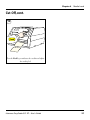
Adjust the position of the green edge guide so the Route the media through the cutter between the
media is guided with a minimum of play.
two guide plates.
12
13
TEAR
-OFF
INTH
T PR
RTAN
PO
IM
s
bontr
er rib l
nsf therma
I
l tra
lt
rma . UB
rma
the rranty
the codes
l and bar e to
of any wa
ead
rma tingprovid ided
use
The printh
of the
nd/ d/prov
of prin
me
lity
the
qua quality om mende
The the we rec om
for er
I rec
pap y UB
onl
Close the cutter unit while pulling at the end of the Switch on the power using the On/Off switch on
media. Close the right-hand door.
the rear plate.
26
Intermec EasyCoder 501 XP – User’s Guide
Chapter 4
Media Load
Cut-Off, cont.
14
Feed
Press the Feed key to advance the media and adjust
the media feed.
Intermec EasyCoder 501 XP – User’s Guide
27
Chapter 4
Media Load
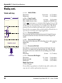
Peel-Off (Self-strip)
The EasyCoder 501 XP can print on labels, tickets, tags, and
continuous stock in various forms. This chapter describes the
case when precut labels fitted on liner (backing paper) are to be
separated from the liner immediately after printing. This requires
an optional internal liner/batch takeup unit, on which the liner
is wound up after the labels have been printed and dispensed.
This is also known as “Self-strip” operation.
Use the <Feed> key (see figure #15) when loading the same type
of media as before. When switching to a new type of media, or if
the printer does not feed out the media properly, simultaneously
press the <Shift> and <Feed> keys to perform a “testfeed.”
Peel-off can be used for:
• Self-adhesive labels fitted on liner.
An optional label taken sensor can hold the printing of next label
in a batch until the present label has been removed, see Chapter
9, “Options.”
2
1
Open the front and right-hand doors.
28
Turn the printhead lift lever to ”Open” position.
Intermec EasyCoder 501 XP – User’s Guide
Chapter 4
Media Load
Peel-Off, cont.
4
3
2.
1.
Pull out the green clip (1) on the liner takeup hub
and dispose of any wound-up liner (2.)
5a
Remove any core from the media supply hub.
5b
mm
38-40 )
(1.5"
m
76 m
(3")
Fit a new media roll on the media supply hub and In case of media roll with a 76 mm (3-inch) core,
push the roll inwards as far as it will go.
first fit an adapter on the media supply hub.
Intermec EasyCoder 501 XP – User’s Guide
29
Chapter 4
Media Load
Peel-Off, cont.
7
6
Route the media underneath the slack absorber and
forward towards the print unit. The slack absorber Route the media through the print unit and push it
can be rotated for better access.
inwards as far as it will go.
8
9
Powe
r
FF
R-O
TEA
NT
RTA
PR
e
ansf t
al tr UBI
y.
erm
y th arrant
dt
of and w
al ang b
use thea
erm tin
PO
IM
Pull out approximately 40 cm (15 inches) of labels Route the liner around the tear bar and back under
and remove the labels from the liner.
the print unit.
30
Intermec EasyCoder 501 XP – User’s Guide
Chapter 4
Media Load
Peel-Off, cont.
10
11
1.
2.
Secure the liner with the clip (1) and rotate the hub This diagram shows the paths of the labels and
the liner.
so the media becomes tight (2.)
12
Turn the printhead lift lever to “Closed” position.
Intermec EasyCoder 501 XP – User’s Guide
13
Adjust the position of the green edge guide so the
media is guided with a minimum of play.
31
Chapter 4
Media Load
Peel-Off, cont.
14
15
Feed
Close the front and right-hand doors.
32
Press the Feed key to advance the media and adjust
the media feed.
Intermec EasyCoder 501 XP – User’s Guide
Chapter 4
Media Load
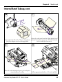
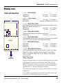
Internal Batch Takeup
The EasyCoder 501 XP can print on labels, tickets, tags, and
continuous stock in various forms. This chapter describes the
case when printed labels fitted on liner (backing paper) or preperforated tickets and tags are wound up inside the printer. The
roll of printed labels, tickets, or tags can then be removed and be
handled manually. This requires an optional internal liner/batch
takeup unit.
The takeup hub can accommodate 1/4 to 1/3 of a full-size media
roll.
Use the <Feed> key (see figure #16) when loading the same type
of media as before. When switching to a new type of media, or if
the printer does not feed out the media properly, simultaneously
press the <Shift> and <Feed> keys to perform a “testfeed.”
Internal batch takeup can be used for:
• Self-adhesive labels fitted on liner
• Preperforated tickets with gaps
• Preperforated tickets with marks
1
2
Open the front and right-hand doors.
Intermec EasyCoder 501 XP – User’s Guide
Turn the printhead lift lever to “Open” position.
33
Chapter 4
Media Load
Internal Batch Takeup, cont.
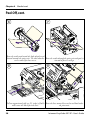
3
Remove any core from the media supply hub.
5
4
Loosen the single screw that holds the guide plate at
the rear of the media compartment.
6a
mm
38-40 )
(1.5"
Remove the tear bar from the print unit and replace Fit a new media roll on the media supply hub and
push the roll inwards as far as it will go.
it with the guide plate.
34
Intermec EasyCoder 501 XP – User’s Guide
Chapter 4
Media Load
Internal Batch Takeup, cont.
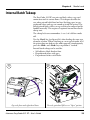
7
6b
m
76 m
(3")
Route the media underneath the slack absorber and
In case of media roll with a 76 mm (3-inch) core, forward towards the print unit. The slack absorber
first fit an adapter on the media supply hub.
can be rotated for better access.
8
9
/15"
m
c
40
Route the media through the print unit and push it
inwards as far as it will go.
Pull out approximately 40 cm (15 inches) of labels.
Intermec EasyCoder 501 XP – User’s Guide
35
Chapter 4
Media Load
Internal Batch Takeup, cont.
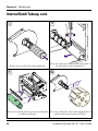
11
10
1.
2.
-OFF
TEAR
IN
PR
T
bon
r rib l
nsfe erma
l traUBI th
l
erma y.
erma
y th arrant
d th code
l an baride to
of and w
id
use thea
erma
intingprov
The prin
of thof pr end/ d/prov
IM
PO
RTA
NT
Route the labels around the guide plate and back Wind up some of the media on the takeup hub and
under the print unit to the takeup hub.
secure it with the clip.
12
13
This diagram shows the media path.
36
Turn the printhead lift lever to “Closed” position.
Intermec EasyCoder 501 XP – User’s Guide
Chapter 4
Media Load
Internal Batch Takeup, cont.
15
14
TEAR
-OFF
D AN
EA
INTH
n th
tha ons
er ribb
s, other
bontransf
dia
er rib l
er meg lif
nsf therma
th
lon
nsf
I
l tra
l traand a ds of e
rma . UB
rma
s to
the rranty
the codesthe nee
plie
l and bar e to sup
of any wa
ead
rma tingprovid ided
use
The printh
of the
nd/ d/prov
of prin
me
lity
the
qua quality om mende
The the we rec om
for er
I rec
pap y UB
onl
IM
T PR
RTAN
PO
Adjust the position of the green edge guide so the Close the right-hand door but keep the front door
media is guided with a minimum of play.
open.
16
Feed
Press the Feed key to advance the media and adjust
the media feed.
Intermec EasyCoder 501 XP – User’s Guide
37
Chapter 4
Media Load
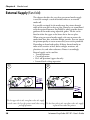
External Supply (Fan-fold)
This chapter describes the case when an external media supply
is used, for example a stack of fan-fold tickets or an external
media roll.
It is possible to simply let the media enter the printer through
either of the two slots in the rear plate. However, we recommend
to fit the optional Intermec Fan-Fold Kit, which provides better
guidance of the media using adjustable guides. The kit can be
fitted to either the upper or the lower slot in the rear plate.
When using an external media supply, take care to protect the
media from dust, dirt, and other foreign particles, that can impair
the printout quality or cause unneccessary wear to the printhead.
Depending on brand and quality, all direct thermal media are
more or less sensitive to heat, direct sunlight, moisture, oil,
plasticizers, fat, and other substances. Protect it accordingly.
External supply can be used for:
• Tear-off operation
• Cut-off operation
• Peel -off operation (upper slot only)
• Internal batch takeup operation
1
2
Use the upper slot in the rear plate when the supply
is at the same level as the printer and when using Use the lower slot in the rear plate when the supply
peel-off operation.
is placed lower than the printer.
38
Intermec EasyCoder 501 XP – User’s Guide
Chapter 4
Media Load
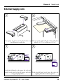
External Supply, cont.
3
4
As an option, the printer can be fitted with a set of The outer guide is adjustable for media widths from
fan-fold guides in either slot.
40 mm (1.575 in.) to 120 mm (4.7 in.).
5
6
Fit the fan fold guide in the upper slot, when the
supply is at the same level as the printer and when Fit the fan fold guide in the lower slot, when the
using peel-off operation.
supply is placed lower than the printer.
Intermec EasyCoder 501 XP – User’s Guide
39
Chapter 5
Thermal Transfer Printing
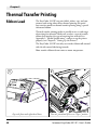
Ribbon Load
The EasyCoder 501 XP can print labels, tickets, tags, and continuous stock using either direct thermal printing on special
heat-sensitive media or thermal transfer printing using a special
ink-coated ribbon.
Thermal transfer printing makes it possible to use a wide range
of receiving face material. Make sure to select a type of transfer
ribbon that matches the type of receiving face material (see
Appendix 2, “Media Specifications”) and to set up the printer
properly (see Chapter 6, “Setting Up the Printer.”)
The EasyCoder 501 XP can only use transfer ribbon rolls wound
with the ink-coated side facing inwards.
Most transfer ribbons do not smear at room temperature.
2
1
Open the front and right-hand doors.
40
Turn the printhead lift lever to ”Open” position.
Intermec EasyCoder 501 XP – User’s Guide
Chapter 5
Thermal Transfer Printing
Ribbon Load, cont.
3
4
In case of ribbon reload, remove any used ribbon Unpack a roll of original Intermec thermal transfer
and empty ribbon core.
ribbon.
5a
5b
60 mm
(2.3")
88 – 90 mm
(3.5")
#2
#1
In case of ribbon up to 60 mm (2.3 inches) wide, In case of 88 to 90 mm (3.5 inches) ribbon width,
compress the ribbon supply bobbin and move it so it compress the ribbon supply bobbin and move it so it
snaps into the first (innermost) groove.
snaps into the 2:nd groove.
Intermec EasyCoder 501 XP – User’s Guide
41
Chapter 5
Thermal Transfer Printing
Ribbon Load, cont.
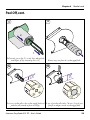
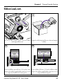
5c
6
1.
110 mm
(4.3")
2.
TEAR
-O
IM
us
The pr
the
The
fo
p
#3
In case of 110 mm (4.3 inches) ribbon width, Press the ribbon roll onto the ribbon supply bobbin
compress the ribbon supply bobbin and move it so it (1) and route the ribbon through the print unit. Pull
out 20 cm (8 inches) of ribbon (2.)
snaps into the 3:rd groove.
7
8
Press the cardboard core at the front end of the ribbon
Without releasing the ribbon, turn the printhead lift onto the rewind hub. During printing, both hubs
lever to “Closed” position to lock the ribbon.
should rotate counterclockwise.
42
Intermec EasyCoder 501 XP – User’s Guide
Chapter 5
Thermal Transfer Printing
Ribbon Load, cont.
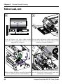
9
Turn the printhead lift lever to “Open” position.
11
Turn the printhead lift lever to “Closed” position.
Intermec EasyCoder 501 XP – User’s Guide
10
Wind up the ribbon until all of the transparent
leader has passed the printhead and the ribbon
becomes tight.
12
Close the front and right-hand doors.
43
Chapter 6
Setting Up the Printer
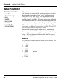
Description
The setup controls the printer in regard of serial communication,
media feed, and print speed, and specifies which type of media
and ribbon are loaded in the printer.
Check the list of the printer’s default setup parameters on the next
page to see if they match your requirements. If not, you will have
to change the setup using one of the methods described below.
The setup may also be changed, manually or automatically, by
Intermec PrintSet, InterDriver, and LabelShop, or by third-party
application programs.
• Setup Mode
- Press the <Setup> key on the printer’s built-in keyboard to
enter the Setup Mode, or
- select the Setup option in Intermec Shell to enter the Setup
Mode, or
- execute the Intermec Fingerprint SETUP instruction to
enter the Setup Mode, or
- access the Setup Mode via the printer’s home page using an
optional EasyLAN 100i interface board.
See Chapter 7, “Setup Mode” in this manual and the documentation of the EasyLAN 100i interface board.
• Intermec Fingerprint
- Use setup strings to change individual setup parameters
remotely from the host, or
- use setup files to create sets of setup parameters remotely
from the host.
See the Intermec Fingerprint v7.61 manuals.
• Intermec Direct Protocol
- Use setup strings to change individual setup parameters
remotely from the host.
See the Intermec Direct Protocol manuals.
44
Intermec EasyCoder 501 XP – User’s Guide
Chapter 6
Default Setup
Setting Up the Printer
The printer’s default setup is listed below:
Ser-Com "uart1:"
Baud rate....................................................
Character length.........................................
Parity ..........................................................
Stop bits .....................................................
RTS/CTS...................................................
ENQ/ACK ................................................
XON/XOFF, data to host..........................
XON/XOFF, data from host .....................
New line.....................................................
Receive buffer.............................................
Transmit buffer ..........................................
9600 bps
8 bits
None
1 bit
Disable
Disable
Disable
Disable
CR/LF
300 bytes
300 bytes
Feedadjust:
Startadjust ..................................................
Stopadjust...................................................
0
0
Media:
X-start.........................................................
Width.........................................................
Length........................................................
Media type .................................................
Paper type...................................................
Ribbon constant.........................................
Ribbon factor.............................................
Label offset .................................................
Low diameter .............................................
Contrast .....................................................
36
1244
1800
Label (w Gaps)
Thermal transfer
90
25
0
36
±0%
Print Defines:
Print speed..................................................
150 mm/sec.
Reading the Current Setup
The printer’s current setup values can be read from the printer’s
display window by browsing through the Setup Mode.
You can list the printer’s current setup values by printing test label
#5 in the Setup Mode or by using Intermec Shell.
The current setup values can be sent to the host via the
standard serial communication channel using a SETUP WRITE
"uart1:" statement (see Intermec Fingerprint v7.61, Programmer’s Reference Manual).
Intermec EasyCoder 501 XP – User’s Guide
45
Chapter 6
Setting Up the Printer
Setup Parameters
Serial Communication
• Baud Rate
• Character Length
• Parity
• Stop Bits
• Flow Control
• New Line
• Receive Buffer
• Transmit Buffer
The serial communication parameters control the communication between the printer and the connected computer or other
devices on the standard serial port "uart1:" and the optional
serial ports "uart2:" and "uart3:". The optional ports require
an optional interface board. The printer’s firmware detects if an
interface board is installed in the printer and presents additional
sets of communication setup menus depending on type of communication (refer to diagrams 3-5 in Chapter 7, “Setup Mode”).
The serial communication parameters have no effect on parallel communications, on Ethernet communications, or on the IN and OUT
ports on the optional Industrial Interface Board.
For the serial communication channel "uart1", the following
parameters can be set. Make sure they match the setup of the
connected device or vice versa. If the setup of the printer and the
setup of the host do not match, the response from the printer
to host will be garbled.
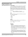
Baud Rate
The baud rate is the transmission speed in bits per second. There
are 9 options:
•
300
•
600
• 1200
• 2400
• 4800
• 9600
• 19200
• 38400
• 57600
46
(default)
Intermec EasyCoder 501 XP – User’s Guide
Chapter 6
Setting Up the Printer
Setup Parameters, cont.
Serial Communication, cont. Character Length
The character length specifies the number of bits that will define
a character. Eight bits are recommended, because that option
allows more special characters and characters specific for foreign
languages to be used. Refer to the Intermec Fingerprint v7.61,
Programmer’s Reference Manual for information on which characters are available in various combinations of character length and
character set.
• 7
• 8
Characters ASCII 000 to 127 decimal
Characters ASCII 000 to 255 decimal (default)
Parity
The parity decides how the firmware will check for transmission
errors. There are five options:
•
•
•
•
•
None (default)
Even
Odd
Mark
Space
Stop Bits
The number of stop bits specifies how many bits will define the
end of a character. There are two options:
• 1
• 2
(default)
Flow Control
• RTS/CTS
RTS/CTS is a protocol where the communication is controlled by currents through separate lines in the cable being set
either to high or low. By default, this option is disabled.
RTS high indicates that the transmitting unit is able to receive
characters. RTS low indicates that the receive buffer is filled to
75% (see XON/XOFF).
CTS high indicates that the unit transmitting the CTS signal
is ready to receive data. CTS low indicates that the receive
buffer is full (see XON/XOFF). In some computer programs,
for example MS Windows Terminal, RTS/CTS is designated
“Hardware.”
Intermec EasyCoder 501 XP – User’s Guide
47
Chapter 6
Setting Up the Printer
Setup Parameters, cont.
Serial Communication, cont. • ENQ/ACK
In this protocol, the communication is controlled by the
control characters ENQ (ASCII 05 dec.) and ACK (ASCII 06
dec.) being transmitted on the same line as the data. The sending unit transmits ENQ at regular intervals. If the response
ACK is not received, the transmission is held up awaiting
an ACK character from the receiving unit. By default, ENQ/
ACK is disabled.
• XON/XOFF
In this protocol, the communication is controlled by the
control characters XON (ASCII 17 dec.) and XOFF (ASCII
19 dec.) being transmitted on the same line as the data. XON/
XOFF can be enabled/disabled separately for data received
from the host by the printer (printer sends XON/XOFF) and
for data transmitted to the host from the printer (host sends
XON/XOFF).
XOFF is sent from the printer when its receive buffer is
filled to 75%, and the transmission from the host is held,
waiting for an XON character. When enough data have been
processed so the receive buffer is filled only to 50%, the printer
sends an XON character and the host resumes transmitting
data. The same principles apply to XON/XOFF sent by the
host, even if the percentage figure may differ.
By default, XON/XOFF is disabled for data both ways.
New Line
Selects the character(s) transmitted from the printer to specify the
switching to a new line. There are three options:
• CR/LF
• LF
• CR
ASCII 13 dec. + ASCII 10 dec. (default)
ASCII 10 dec.
ASCII 13 dec.
Receive Buffer
The receive buffer stores the input data received on the serial
channel before processing. Default size is 300 bytes.
Transmit Buffer
The transmit buffer stores the output data to be transmitted on
the serial channel before transmission. Default size is 300 bytes.
48
Intermec EasyCoder 501 XP – User’s Guide
Chapter 6
Setting Up the Printer
Setup Parameters, cont.
Feedadjust
• Startadjust
• Stopadjust
The Feedadjust part of the Setup Mode controls how much of
the media is fed out or pulled back before and/or after the actual
printing. These settings are global and will be effected regardless
of which program is run.
Note that the firmware uses the front edges of labels w. gaps, the ends
of detection slots, and the forward edges of black marks for detection,
all seen in relation to the feed direction.
Recommended Feed Adjustments
The following settings allow
printing from the top of the
label. Minor deviations from
the recommended values may
be required due to various
combinations of media types,
roll size, type of media supply
device, and individual differences between printers.
Tear-Off:
Start adjust: -175 dots
Stop adjust: 0 dots
Cut between labels:
Start adjust: -441 dots
Stop adjust: 270 dots
Cut variable length strip:
Start adjust: -441 dots
Stop adjust: 375 dots
Peel-Off:
Start adjust: -115 dots
Stop adjust: -60 dots
Start Adjust
The Start Adjust value is given as a positive or negative number
of dots (1 dot = 0.125 mm = 4.9 mils). Default value is 0, which
places the origin a certain distance back from the forward edge
of the copy.
• A positive start adjustment means that the specified length
of media will be fed out before the printing starts. Thus, the
origin is moved further back from the forward edge of the
copy.
• A negative start adjustment means that the specified length of
media will be pulled back before the printing starts. Thus, the
origin is moved towards the forward edge of the copy.
Stop Adjust
The Stop Adjust value is given as a positive or negative number
of dots (1 dot = 0.125 mm = 4.9 mils). Default value is 0,
which stops the media feed in a position suitable for tear off
operation.
• A positive stop adjustment means that the normal media
feed after the printing is completed will be increased by the
specified value.
• A negative stop adjustment means that the normal media
feed after the printing is completed will be decreased by the
specified value.
Intermec EasyCoder 501 XP – User’s Guide
49
Chapter 6
Setting Up the Printer
Setup Parameters, cont.
Media
• Media Size
• Media Type
• Paper Type
• Testfeed
• Contrast
The media parameters tell the firmware the characteristics of
the media that will be used, so the printout will be positioned
correctly and get the best quality possible.
Media Size
The size of the printable area is defined by three parameters;
X-Start, Width, and Length.
X-Start
Specifies the position of the origin along the dots on the printhead.
By default, X-start is 36 dots, which places the inner margin of the
print area 3 mm (0.118 inches) from the inner edge of the media
and gives a maximum print width of 1244 dots (103.7 mm/4.1
inches). This prevents printing outside labels when the liner is
slightly wider than the labels.
If you want to use the entire media width, reset the X-start
value to 0 which gives a maximum print width of 1280 dots
(106.6 mm/4.2 inches).
By increasing the value for the X-start parameter, the origin will
be moved outwards, away from the inner edge of the media path.
In other words, the larger X-start value, the wider inner margin
and the less available print width.
Width
Specifies the width of the printable area in number of dots from
the origin. Thus, the sum of the X-start and width values gives
the outer margin of the printable area. The width should be
set to prevent printing outside the media, which may harm the
printhead.
Length
Specifies the length of the printable area in number of dots from
the origin along the Y-coordinate and allocates memory space for
two identical image buffers in the printer’s temporary memory.
The size of each buffer can be calculated using this formula:
Buffer size (bits) = [Print length in dots] x [Printhead width in dots]
Note that the temporary memory has other functions that also require
some memory space. To obtain a longer print area, the memory can
be increased by fitting a larger DRAM SIMM on the printer’s CPU
board as described in the Service Manual.
50
Intermec EasyCoder 501 XP – User’s Guide
Chapter 6
Setting Up the Printer
Setup Parameters, cont.
Length, cont.
• The length setup also decides the amount of media feed when
using “fix length strip.”
• The length setup creates an emergency stop, which works
when the printer is set up for “Label (w gaps)”, “Ticket (w
mark)”, or “Ticket (w gaps).” If the label stop sensor (LSS) has
not detected a gap or mark within 150% of the set length,
the media feed is automatically stopped to avoid feeding out a
whole roll of media, because of an LSS malfunction.
Media, cont.
By setting up the X-start, the Width, and the Length, you
will create a print window inside which the printing can be performed. Any object or field extending outside the print window
in any direction will either be clipped or cause an error condition
(Error 1003 “Field out of label”), see Intermec Fingerprint v7.61,
Programmer’s Reference Manual.
13.4 mm (0.52 in)
max. 106.6 mm (4.2 in)
Length
Dot-line
on printhead
PRINT
WINDOW
Origin
X-start
Dot #0
Width (1-1280)
FEED
DIRECTION
Dot #127
25-120 mm (1-4.7 in)
Intermec EasyCoder 501 XP – User’s Guide
51
Chapter 6
Setting Up the Printer
Setup Parameters, cont.
Media, cont.
Media Type
The Media Type parameters control how the label stop sensor
(LSS) and the media feed work. There are five media type
options:
• Label (w gaps) is used for adhesive labels mounted on liner.
• Ticket (w mark) is used for labels, tickets, or continuous stock
provided with black marks at the back.
• Ticket (w gaps) is used for tickets and tags with detection
slits.
• Fix length strip is used for continuous stock where the length
of the print window decides the length of media to be fed out.
• Var length strip is used for continuous stock and adds 115
dots of media feed after the last printable dot (may even be a
blank space character or a “white dot” in an image or character
cell) to allow the media to be properly torn off.
It is important to select the correct media type, so the printer can
indicate possible errors. Two error conditions may occur:
• Error 1005 “Out of paper” indicates that the last ordered copy
could not be printed because of an empty media stock.
• Error 1031 “Next label not found” indicates that the last
ordered label or ticket was successfully printed, but no more
labels/tickets can be printed because of an empty media stock.
52
Intermec EasyCoder 501 XP – User’s Guide
Chapter 6
Setting Up the Printer
Setup Parameters, cont.
Media, cont.
Paper Type
The Paper Type parameters control the heat emitted from the
printhead to the direct thermal media or the transfer ribbon in
order to produce the dots that make up the printout image. Start
by choosing between two alternatives:
• Thermal Transfer printing
(default)
• Direct Thermal printing (option)
Your choice will decide which parameters to enter next:
Thermal Transfer Printing (option)
This option contains four parameters:
• Ribbon Constant
(range 50 to 115)
• Ribbon Factor
(range 10 to 50)
• Label Offset
(range -50 to 50)
Direct Thermal Printing
This option contains two parameters:
• Label Constant
(range 50 to 115)
• Label Factor
(range 10 to 50)
Intermec EasyCoder 501 XP – User’s Guide
53
Chapter 6
Setting Up the Printer
Setup Parameters, cont.
Media, cont.
Thermal Transfer Printing
Keep the Ribbon Factor for each ribbon type at the recommended value. Decrease or increase the Ribbon Constant for
lighter or darker images respectively. For a new label material,
start with an average Ribbon Constant value for the ribbon
quality in question.
Direct Thermal Printing
Intermec recommends that you use the paper type and print
speed settings listed below to produce the highest possible print
quality under normal conditions and to ensure maximum lifetime of the printhead. Label materials are available from Intermec
either in standard types and sizes, or in special materials and sizes.
When adjusting the image darkness for individual requirements
or new label materials, keep the Label Factor at the recommended
value for the type of direct thermal media. Decrease or increase
the Label Constant for lighter or darker images respectively,
depending on the requirements of the images or of the new label
material.
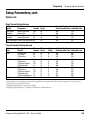
Bar Code Directions
Picket Fence
Bar Code Directions
In the tables on the pages that follow, different maximum print
speeds may be recommended depending on the direction of
possible bar codes in the printout. Generally, ladder style bar
codes are more demanding and may require a lower print speed,
especially in connection with a large media roll and/or negative
start adjust values (see “Print Speed” later in this chapter). The
illustration to the left shows how the two type of bar code
directions relate to the media feed direction.
Ladder
Feed
Direction
54
Intermec EasyCoder 501 XP – User’s Guide
Chapter 6
Setting Up the Printer
Setup Parameters, cont.
Media, cont.
Direct Thermal Printing (Europe)
DT Type/
Speed
Top Coated/
Standard
Non Top Coated/
Standard
Media
Designation
Thermal Top Board3
Thermal Top
Thermal Eco
Thermal Eco Board3
Label
Constant
100
95
85
80
Top Coated/High Thermal Top High Speed 80
Label
Factor
40
40
40
40
Max Rec. Print Speed (mm/sec)1
Picket Fence Bar Code2 Ladder Bar Code
200
150
200
200
200
200
200
150
30
250
250
Thermal Transfer Printing (Europe)
Ribbon
Type
GP02
HP07
HP66
HR03
Receiving
Material
TTR Uncoated
TTR Coated
TTR Premium
TTR Coated
TTR Premium
TTR Premium Board3
TTR Polyethylene
TTR Coated
TTR Premium
TTR Premium Board3
TTR Polyethylene
TTR Gloss Polyethylene
TTR High Gloss Polyester
Ribbon
Constant
80
80
70
100
90
105
85
100
90
105
85
90
100
Ribbon
Factor
25
25
25
25
25
25
25
25
25
25
25
25
30
Label
Offset
0
0
0
0
0
0
0
0
0
0
0
0
0
Max Rec. Print Speed (mm/sec)1
Picket Fence Bar Code2 Ladder Bar Code
200
200
200
200
250
250
225
200
300
225
100
100
200
200
250
200
300
250
250
200
225
200
200
200
250
200
1
/. Exceeding the recommended print speed may cause the printhead to wear out prematurely. If the ambient temperature is lower than +15°C
(+59°F), decrease print speed by 100 mm/sec.
2
/. Also applies to printing of text, images, lines, and boxes.
3
/. Requires high printhead pressure (see Chapter 12 “Adjustments, Printhead Pressure”).
Intermec EasyCoder 501 XP – User’s Guide
55
Chapter 6
Setting Up the Printer
Setup Parameters, cont.
Media, cont.
Direct Thermal Printing (North America)
DT Type/
Speed
Top Coated/
Standard
Top Coated/
High
Media
Designation
Duratherm II Tag3
Duratherm II
Duratherm Ltg
Duratherm IR
Label
Constant
112
110
92
82
Max Rec. Print Speed (mm/sec)1
Picket Fence Bar Code2 Ladder Bar Code
100
100
100
100
175
175
150
150
Label
Factor
40
40
40
40
Thermal Transfer Printing (North America)
Ribbon
Type
TMX 1500
TMX 2500
TMX 3200
Receiving
Material
Duratran I
Duratran VG
Duratran II
Duratran II Tag
Kimdura
Kimdura Tag
Duratran II
Duratran II Tag
Kimdura
Kimdura Tag
Polyester
Ribbon
Constant
65
65
65
65
65
65
60
60
60
60
90
Ribbon
Factor
25
25
25
25
25
25
25
25
25
25
30
Label
Offset
2
15
0
4
20
15
0
4
20
15
0
Max Rec. Print Speed (mm/sec)1
Picket Fence Bar Code2 Ladder Bar Code
200
200
250
250
250
250
250
250
250
250
250
250
300
300
225
225
300
300
300
300
150
150
1
/. Exceeding the recommended print speed may cause the printhead to wear out prematurely. If the ambient temperature is lower than +15°C (+59°F), decrease print speed by 100 mm/sec.
2
/. Also applies to printing of text, images, lines, and boxes.
3
/. Requires high printhead pressure (see Chapter 12 “Adjustments, Printhead Pressure”),
56
Intermec EasyCoder 501 XP – User’s Guide
Chapter 6
Setting Up the Printer
Setup Parameters, cont.
Media, cont.
Contrast
Use the contrast parameter to make minor adjustments of the
blackness in the printout, for example to adapt the printer to
variations in quality between different batches of the same media.
11 options are displayed in an endless loop from -10% to +10%.
Default value is 0%. The contrast is reset to the default (±0)
whenever a new paper type is specified, regardless which method
has been used.
Testfeed
The sensitivity of the label stop sensor (LSS) may need to be
adjusted when switching from one type of media to another.
This is especially the case when using adhesive labels since the
transparency of the liner (backing paper) may vary. Adjusting
the LSS entails feeding out a number of blank copies until
the firmware has decided the proper setting for the LSS. At
the same time, the front edges of the labels, tickets, etc. are
detected so the feed control can position the media according
to the Feedadjust parameter (same as the Intermec Fingerprint
statement TESTFEED). The comparator and amplifier values of
the LSS are displayed (read-only information).
Print Defines
• Head Resistance
• Testprint
• Print Speed
Head Resistance
The printhead resistance is measured automatically at startup
(read-only information).
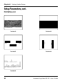
Testprint
Test label #1 to #4 check the printout quality and facilitate
adjustment of the printhead pressure, see Chapter 12, “Adjustments.” Test label #5 lists the printer’s current setup (extra labels
may be printed if the printer is fitted an optional interface
board). Test label #6 is only printed if the printer has an optional
EasyLAN 100i interface board. Test labels #1 to #5 are illustrated
on the next page. If the printer refuses to print a test label, press
the <F3> key to find out what is wrong, for example printhead
lifted or out-of paper.
Intermec EasyCoder 501 XP – User’s Guide
57
CODE39
58
CODE39
Test Label #3
CODE39
Test Label #1
CODE39
UART1
9600-8-N-1
RTS/CTS
DISABLE
ENQ/ACK
DISABLE
XON/XOFF
DATA TO HOST
DISABLE
DATA FROM HOST
DISABLE
NEW LINE
CR/LF
REC BUF
300
TRANS BUF
300
PRINT CONFIG
STARTADJ
0
STOPADJ
0
XSTART
36
WIDTH
1244
LENGTH
1800
MEDIA TYPE
LABEL (w GAPS)
PAPER TYPE
TRANSFER
LABEL CONSTANT
100
LABEL FACTOR
40
RIBBON CONSTANT
100
RIBBON FACTOR
25
LABEL OFFSET
0
CONTRAST
+0%
TESTFEED
12 3
HEAD RESIST
1164
PRINT SPEED
150
Odometer [km]
0
Model
501XP
Hardware version
1.1
Ram 4096 ( k)
Fos 0+0+2048 (k)
External 0 (k)
FIRMWARE
Fingerprint 7.40
MCS0857 xx-xxx-00 xx:xx:xx m3k
slav0738 01-Apr-97 12:3:56 [0]
slav0738 01-Apr-97 12:3:56 [1]
Chapter 6
Setting Up the Printer
Setup Parameters, cont.
Print Defines, cont.
1109 ohms/12 dots
Test Label #2
1 23 45 67 890 12 8
Test Label #4
Test Label #5
Intermec EasyCoder 501 XP – User’s Guide
Chapter 6
Setting Up the Printer
Setup Parameters, cont.
Print Defines, cont.
Print Speed
The print speed is variable between 100 and 300 mm/sec.
Generally, the lower the speed, the better the printout quality.
This is especially true when printing bar codes with the bars
running across the media path (“ladder style”), when printing
on demanding face materials, and when printing at low ambient
temperatures. Refer to the tables under “Media” earlier in this
chapter for maximum print speed values. The default setting is
150 mm/sec. (≈ 6 inches/sec.).
Intermec EasyCoder 501 XP – User’s Guide
59
Chapter 7
Setup Mode
Entering Setup Mode at Installation
The method of entering the Setup Mode depends on which startup
files are stored in the printer’s memory, a subject that was more
thoroughly discussed in Chapter 3, “Starting Up.”
EasyCoder 501 XP with Intermec Shell
• Switch on the power.
• When the display shows the message “Enter=Shell; x sec...”,
press <Enter>.
• Press <Setup> (this facility can be used anywhere within
Intermec Shell).
• Set up the printer as described in this chapter.
• Return to Intermec Shell by pressing <Setup>.
EasyCoder 501 XP with a custom-made application program
• Normally, there is no need to enter the Setup Mode for
custom-made application programs. Necessary provisions for
changing the setup, manually or automatically, should be
provided by the program.
60
Intermec EasyCoder 501 XP – User’s Guide
Chapter 7 Setup Mode
Navigating in Setup Mode
While going through the setup procedure, you are guided by texts
in the printer’s display. You can navigate between setup menus,
acknowledge displayed values, select or type new values, etc. by
using the keys on the printer’s keyboard.
Note!
An external keyboard cannot be used inside the Setup Mode.
Move one menu to the left on the same
level1.
Move one menu to the right on the same
level1.
Display error message at test label printing failure.
Move up one level or scroll back in a stack
of options1.
Move down one level or scroll forward in
a stack of options1.
-
Enter numeric values.
Specify negative values (leading position).
Clear erroneously entered values.
Acknowledge and move to next menu.
Perform testfeeds in the Testfeed menu.
Print test labels in the Test Label menu.
Exit the Setup Mode.
Can be used anywhere in Setup Mode.
1
/. “Left”, “right”, “up”, and “down” refer to the overviews later in
this chapter.
Intermec EasyCoder 501 XP – User’s Guide
61
Chapter 7 Setup Mode
Setup Mode Overview, Part 1
(Intermec Fingerprint v7.61)
SETUP:
SER-COM,UART1
SER-COM,UART1:
BAUDRATE
SETUP:
SER-COM,UART2
See Overview Part 3
SETUP:
SER-COM,UART3
See Overview Part 4
SETUP:
NET-COM,NET1
See Overview Part 5
DETECTION:
SETUP:
FEEDADJ
BAUDRATE:
9600
19200
38400
57600
115200
300
600
1200
2400
4800
LEGEND:
Boxes with thick lines indicate default setup.
Boxes with dotted lines indicate menus related to
optional interface boards.
SER-COM,UART1:
CHAR LENGTH
CHAR LENGTH:
8
7
SER-COM,UART1:
PARITY
PARITY:
NONE
EVEN
ODD
MARK
SPACE
SER-COM,UART1:
STOP BITS
STOPBITS:
1
2
SER-COM,UART1:
FLOWCONTROL
FLOWCONTROL:
RTS/CTS
RTS/CTS:
DISABLE
ENABLE
FLOWCONTROL:
ENQ/ACK
ENQ/ACK:
DISABLE
ENABLE
FLOWCONTROL:
XON/XOFF
XON/XOFF:
DATA TO HOST
DATA TO HOST:
DISABLE
ENABLE
SER-COM,UART1:
NEW LINE
NEW LINE:
CR/LF
LF
CR
XON/XOFF:
DATA FROM HOST
DATA FROM HOST:
DISABLE
ENABLE
SER-COM,UART1:
REC BUF
REC BUF:
[300]:
SER-COM,UART1:
TRANS BUF
TRANS BUF:
[300]:
FEEDADJ:
STARTADJ
STARTADJ:
[0]:
FEEDADJ:
STOPADJ
STOPADJ:
[0]:
Continued on next page!
62
Intermec EasyCoder 501 XP – User’s Guide
Chapter 7 Setup Mode
Setup Mode Overview, Part 2
(Intermec Fingerprint v7.61)
Continued from previous page!
SETUP:
MEDIA
MEDIA:
MEDIA SIZE
SETUP:
PRINT DEFS
MEDIA SIZE:
XSTART
XSTART:
[36]:
MEDIA SIZE:
WIDTH
WIDTH:
[1244]:
MEDIA SIZE:
LENGTH
LENGTH:
[1800]:
MEDIA:
MEDIA TYPE
MEDIA TYPE:
LABEL (w GAPS)
TICKET (w MARK)
TICKET (w GAPS)
FIX LENGTH STRIP
VAR LENGTH STRIP
MEDIA:
PAPER TYPE
PAPER TYPE:
TRANSFER
TRANSFER:
RIBBON CONSTANT
RIBBON CONSTANT:
[90]:
TRANSFER:
RIBBON FACTOR
RIBBON FACTOR:
[25]:
TRANSFER:
LABEL OFFSET
LABEL OFFSET:
[0]:
PAPER TYPE:
DIRECT THERMAL
DIRECT THERMAL:
LABEL CONSTANT
LABEL CONSTANT:
[85]:
MEDIA:
CONTRAST
CONTRAST:
+0%
+2%
+4%
+6%
+8%
MEDIA TYPE:
+10%
-10%
-8%
-6%
-4%
-2%
DIRECT THERMAL:
LABEL FACTOR
LABEL FACTOR:
[40]:
MEDIA:
TESTFEED
TESTFEED:
[14 1]
PRINT DEFS:
HEAD RESIST
HEAD RESIST:
[nnn]:
PRINT DEFS:
TESTPRINT
<ENTER> = PRINT:
<F5> = NEXT #1
PRINT DEFS:
PRINT SPEED
PRINT SPEED:
[100]:
• Press <Enter> to perform a Testfeed.
• Comparator and amplifier values are read-only.
Read-only value.
Printhead resistance is
automatically set at startup.
Use <F5> to select type of test label.
Press <Enter> to print it.
If no label is printed, press <F3> for error message.
SETUP:
NETWORK
See Overview Part 5
• Press <Setup> to exit the Setup Mode.
Intermec EasyCoder 501 XP – User’s Guide
63
Chapter 7 Setup Mode
Setup Mode Overview, Part 3
(Intermec Fingerprint v7.61)
If an optional Double Serial or Industrial Interface Board is installed in the printer, additional menus will be displayed
(in case of Double Serial Interface Board, also see Overview Part 4):
SETUP:
SER-COM,UART2
SER-COM,UART2:
BAUDRATE
BAUDRATE:
9600
19200
38400
57600
300
600
1200
2400
4800
SER-COM,UART2:
PROT ADDR
PROT ADDR:
DISABLE
ENABLE
These menus are only displayed if RS 485 is selected on "uart2:"
SER-COM,UART2:
CHAR LENGTH
CHAR LENGTH:
8
7
These menus are not displayed if RS 485 is selected on "uart2:"
SER-COM,UART2:
PARITY
PARITY:
NONE
EVEN
ODD
MARK
SPACE
SER-COM,UART2:
STOP BITS
STOPBITS:
1
2
SER-COM,UART2:
FLOWCONTROL
FLOWCONTROL:
RTS/CTS
RTS/CTS:
DISABLE
ENABLE
FLOWCONTROL:
ENQ/ACK
ENQ/ACK:
DISABLE
ENABLE
FLOWCONTROL:
XON/XOFF
XON/XOFF:
DATA TO HOST
DATA TO HOST:
DISABLE
ENABLE
SER-COM,UART2:
NEW LINE
NEW LINE:
CR/LF
LF
CR
XON/XOFF:
DATA FROM HOST
DATA FROM HOST:
DISABLE
ENABLE
SER-COM,UART2:
REC BUF
REC BUF:
[300]:
SER-COM,UART2:
TRANS BUF
TRANS BUF:
[300]:
SER-COM,UART2:
CONNECTED HW
CONNECTED HW:
RS232
SER-COM,UART2:
PROTOCOL ADDR.
PROTOCOL ADDR.
[1]:
SETUP:
SER-COM,UART3
64
RTS/CTS flowcontrol cannot be
selected for the following types of
hardware connection on "uart2:":
• 422 NON ISOLATED
• 422 ISOLATED
The selected type of hardware connection on "uart2:"
is displayed as one of the following alternatives (read-only):
• RS232
• 422 NON ISOLATED
• 422 ISOLATED
• RS485
These menus are only displayed if RS 485 is selected on "uart2:"
Enter printer's protocol address (0–31).
Intermec EasyCoder 501 XP – User’s Guide
Chapter 7 Setup Mode
Setup Mode Overview, Part 4
(Intermec Fingerprint v7.61)
If an optional Double Serial Interface Board is installed in the printer, additional menus will be displayed:
SETUP:
SER-COM,UART3
SER-COM,UART3:
BAUDRATE
BAUDRATE:
9600
19200
38400
57600
300
600
1200
2400
4800
SER-COM,UART3:
CHAR LENGTH
CHAR LENGTH:
8
7
SER-COM,UART3:
PARITY
PARITY:
NONE
EVEN
ODD
MARK
SPACE
SER-COM,UART3:
STOP BITS
STOPBITS:
1
2
SER-COM,UART3:
FLOWCONTROL
FLOWCONTROL:
RTS/CTS
RTS/CTS:
DISABLE
ENABLE
FLOWCONTROL:
ENQ/ACK
ENQ/ACK:
DISABLE
ENABLE
FLOWCONTROL:
XON/XOFF
XON/XOFF:
DATA TO HOST
DATA TO HOST:
DISABLE
ENABLE
SER-COM,UART3:
NEW LINE
NEW LINE:
CR/LF
LF
CR
XON/XOFF:
DATA FROM HOST
DATA FROM HOST:
DISABLE
ENABLE
SER-COM,UART3:
REC BUF
REC BUF:
[300]:
SER-COM,UART3:
TRANS BUF
TRANS BUF:
[300]:
SER-COM,UART3:
CONNECTED HW
CONNECTED HW:
RS232
Intermec EasyCoder 501 XP – User’s Guide
RTS/CTS flowcontrol cannot be
selected for the following types of
hardware connection on "uart3:":
• 422 NON ISOLATED
• 20 mA CURRENT LOOP
The selected type of hardware connection on "uart3:"
is displayed as one of the following alternatives (read-only):
• RS232
• 422 NON ISOLATED
• CURRENT LOOP
65
Chapter 7 Setup Mode
Setup Mode Overview, Part 5
(Intermec Fingerprint v7.61)
If an optional an EasyLAN 100i interface board is installed in the printer, additional menus will be displayed.
SETUP:
SER-COM, UART1
SETUP:
NET-COM, NET1
Standard Setup Mode
See Overview Part 1
NET-COM,NET1:
NEW LINE
SETUP:
FEEDADJ
Standard Setup Mode
See Overview Part 1
SETUP:
MEDIA
Standard Setup Mode
See Overview Part 2
SETUP:
PRINT DEFS
Standard Setup Mode
See Overview Part 2
Read
Set
NETWORK:
IP SELECTION
Read
SETUP:
NETWORK
NEW LINE:
CR/LF
LF
CR
IP SELECTION:
MANUAL
DHCP
BOOTP
RARP
NETWORK:
IP ADDRESS
IP ADDRESS:
192.168.1.79
NETWORK:
NETMASK
NETMASK:
255.255.255.0
NETWORK:
DEFAULT ROUTER
DEFAULT ROUTER:
192.168.1.1
Use <.> and <0> - <9>
to set IP address.
Use <C> to erase.
Use <.> and <0> - <9>
to set netmask.
Use <C> to erase
Use <.> and <0> - <9>
to set default router.
Use <C> to erase.
• Press <Setup> to exit the Setup Mode.
66
Intermec EasyCoder 501 XP – User’s Guide
Chapter 8
Intermec Shell Startup Program
Introduction
Intermec Shell is a startup program (also called “autoexec-file”),
which is a program that automatically starts running when the
printer is switched on. Intermec Shell helps the operator to
choose between a number of standard or custom-made application programs and to start certain useful facilities, as listed below.
Application Programs
• Intermec LabelShop
• Intermec Windows Driver
• Intermec Fingerprint
(WYSIWYG label design program)
(do not use)
(for creating your own programs or
to run the Intermec InterDriver)
• Intermec Direct Protocol
(easy-to-use slave protocol)
• LINE_AXP.PRG
(line analyzer program)
• Other application programs in the printer’s memory..
A prerequisite is that the program is provided with the extension
“.PRG”. However, some original Intermec utility programs are
excluded as long as they remain stored in "rom:":
- ERRHAND.PRG
- FILELIST.PRG
- LBLSHTXT.PRG
- MKAUTO.PRG
- SHELLXP.PRG
- WINXP.PRG
Other Facilities
• Setup Mode
• Print Setup
• Testfeed
• Test Label
• Default setup
• Update PC card
• Reboot
(manual setup from printer’s keyboard)
(printing setup on label)
(formfeeds + auto-adjust of the LSS)
(printing of test labels)
(resetting all setup parameters to default)
(downloading data from a host to a PC
card in the printer, or upgrading the
printer’s firmware from a PC card)
(restarting the printer)
Intermec Shell is factory-installed in the printer’s permanent
memory (device "rom:"). If you insert a memory card with another
startup file before you switch on the printer, or if there is a startup
file stored in the printer’s permanent memory (device "c:"), this
startup file will be used instead of Intermec Shell (see Chapter 3,
“Startup Files”).
Intermec EasyCoder 501 XP – User’s Guide
67
Chapter 8 Intermec Shell Startup Program
Starting with Intermec Shell
A few seconds after you have switched on the power to the printer and
the initialization is completed, the countdown menu of the Intermec
Shell program will be displayed:
ENTER=SHELL
5 sec.
v.4.8
Now you have 5 seconds to enter Intermec Shell by pressing <Enter>.
The lower line tells you how much time you have left. Should the
time run out before you have taken any action to enter Intermec
Shell, the last selected application in Intermec Shell will be opened. If
you use the same application all the time, you will only need to switch
on the power, once the application has been selected.
If no other application has yet been selected, the current version
of Intermec Fingerprint will be opened with the standard RS-232
port "uart1:" selected as std I/O channel (see Intermec Fingerprint
manuals). When the countdown is completed, you will see these lines
in the display:
FINGERPRINT
7.61
If you want to select another application, just cycle the power and
enter Intermec Shell before the countdown is completed.
When you enter the Intermec Shell from the countdown menus, the
Select Application menu will be displayed:
SHELL
SEL. APPLICATION
In this menu, you can choose between two options:
• Press <Enter> to go to menus where you can select an application
program.
• Press <F5> to go to the Facilities part of Intermec Shell.
68
Intermec EasyCoder 501 XP – User’s Guide
Chapter 8 Intermec Shell Startup Program
Starting with Intermec Shell, cont.
Select Application
In Intermec Shell, the menus present the option in infinite loops,
To see all menus and options, refer to the overview in this chapter.
The Select application lets you choose an application program
that resides in the printer’s memory:
• Current appl. starts the last selected application (by default
Intermec Fingerprint with "uart1:" selected as standard I/O
channel).
1
/.Whenanapplicationprogram
is started, it may automatically
change the communication
setup. For example, Intermec
LabelShop changes the setup
to the following values:
Baud rate:
57600
Char. length:
8
Parity:
None
Stopbits:
1
RTS/CTS:
Enable
ENQ/ACK:
Disable
XON/XOFF:
Disable
New line:
CR/LF
Receive buffer: 600
Transmit buffer: 600
Ifanotherapplicationisselected
later, this communication setup
willremainvalid,unlessthenew
application includes instructionsthatautomaticallychange
the setup. The setup could also
be changed manually in the
Setup Mode.
• LabelShop sets up the printer1 for the various Intermec
LabelShop label formatting programs for Microsoft Windows.
This option requires that you also select a standard IN/OUT
channel, which is the channel you want to use for communication between the printer and the computer. Refer to
the Intermec LabelShop manuals.
• Windows Driver selects the "centronics:" interface as standard IN channel. Use the Intermec Windows Driver to print
from most programs run under Microsoft Window. (To run
the Intermec InterDriver, use the Fingerprint option).
• Fingerprint is used to create, modify, or run programs written
in the Intermec Fingerprint programming language and to
run the Intermec InterDriver. This option requires that you
also select a standard IN/OUT channel, which is the channel
you want to use for communication between the printer and
the computer. Normally, you select "uart1:". Refer to the
Intermec Fingerprint manuals.
• Direct Protocol is an easy-to-use printer protocol for downloading label formats and variable input data to a printer from
a host computer. This option requires that you also select a
standard IN/OUT channel, that is the serial channel you want
to use for communication between the printer and the host.
Normally, you select "uart1:". Refer to the Intermec Direct
Protocol v7.xx manual.
• LINE-ALY.PRG (Line Analyzer) is a Fingerprint program
that captures characters received by the printer on a communication channel and prints them on labels. (See later in
this chapter.)
• Other Application Programs
If the printer contains any other application programs, these
will presented as additional options.
Intermec EasyCoder 501 XP – User’s Guide
69
Chapter 8 Intermec Shell Startup Program
Starting with Intermec Shell, cont.
Select Other Facilities
As an alternative to selecting an application, you can step through
a number of other useful facilities:
• Setup allows you to enter the Setup Mode where you can set
up the printer by means of its built-in keyboard, see Chapter
7, “Setup Mode.”
• Print Setup allows you to produce a printout of the printer’s
current setup values (test label #5).
• Testfeed allows you to feed out a number of label, ticket,
tag, or portions of continuous stock while the printer autoadjusts its media feed and label stop/black mark sensor. It is
recommended to perform a Testfeed each time you load a roll
of labels from a new batch or a different brand.
• Test Label allows you to print a series of four test labels (test
labels #1 to #4) in order to test the printout quality and
printhead alignment. The labels are presented in an infinite
loop, so you can print the series over and over again. Press
<Enter> for each new label.
• Default Setup allows you to reset all setup parameters to
their default values, as listed in Chapter 6, “Setting Up the
Printer.”
• Software Update is used for two purposes:
- Update PC card allows the printer to be used as a Flash
PC card programming device. Using the Zmodem communication tool, files can be downloaded from a PC to
a Flash PC card1 inserted in the memory card slot in the
printer’s rear plate.
Caution! If the Flash PC card contains an earlier firmware
version than the one in the printer, the printer’s firmware will
be downgraded without warning.
- Update firmware is used to upgrade the printer’s firmware
from a new firmware version stored as a file in a PC.
• Reboot has the same effect as cycling the power to the printer.
To exit Intermec Shell without having selected any application, select Reboot. Then wait for the 5 seconds countdown to
finish, and the last selected application will be opened.
1
/. Only Flash PC cards approved
by Intermec can be used.
70
Intermec EasyCoder 501 XP – User’s Guide
Chapter 8 Intermec Shell Startup Program
Intermec Shell v4.8 Diagram
ENTER=SHELL
SHELL
SEL. APPLICATION
5 sec.
SEL. APPLICATION
CURRENT APPL.
v.4.8
ENTER=SHELL
SEL. APPLICATION
4 sec.
LABELSHOP
v.4.8
Last selected application is started
Note: Dotted channels are only shown if
the corresponding optional interface pcb
is fitted.
ENTER=SHELL
SEL. APPLICATION
STD I/O CHANNEL
3 sec.
WINDOWS DRIVER
auto
ENTER=SHELL
SEL. APPLICATION
STD I/O CHANNEL
2 sec.
Fingerprint 7.61
UART1
ENTER=SHELL
SEL. APPLICATION
STD I/O CHANNEL
1 sec.
Direct Protocol
UART2
v.4.8
v.4.8
v.4.8
Last selected
application is started
Default:
Fingerprint 7.61 w. std I/O = "uart1:"
STD I/O CHANNEL
UART3
STD I/O CHANNEL
CENTRONICS
Legend:
The selected application is started
POWER ON
STD I/O CHANNEL
net1:
Return to previous menu.
Proceed to next menu.
SEL.APPL rom:
Accept displayed option
and proceed, or
execute displayed option.
Perform a Testfeed
anywhere in Intermec Shell.
LINE_AXP.PRG
SHELL
SETUP:
SETUP
SER-COM,UART1
SHELL
Prints a list of current setup values (test label #5).
PRINT SETUP
Enter the Setup Mode
from anywhere
in Intermec Shell.
See the chapter “Setup Mode”
SHELL
TESTFEED
Performs a Testfeed (feeds out a number of blank copies
while autoadjusting the label stop sensor.)
SHELL
Prints test labels #1-4 in a loop.
Press Enter for each new label.
TEST LABEL
SHELL
ARE YOU SURE ?
DEFAULT SETUP
DEFAULT SETUP
Y=ENTER/ N=F5
PERFORMED
SHELL
UPDATE:
PC-CARD ERASE
SOFTWARE UPDATE
PC-CARD?
TRANSFER FILE
USING ZMODEM
PROGRAMMING
PC-CARD
PROGRAMMING
COMPLETED
SHELL
UPDATE:
TRANSFER FILE
REBOOT
FIRMWARE
USING ZMODEM
Restarts the printer (same as power off/on)
Intermec EasyCoder 501 XP – User’s Guide
Printer rebooted
automatically.
71
Chapter 8 Intermec Shell Startup Program
Line Analyzer
The Line Analyzer (LINE_AXP.PRG) is a program written in
the Intermec Fingerprint programming language and is intended
to help solving possible communication problems. As the name
implies, the Line Analyzer captures all incoming characters on
a specified communication channel and prints them on one or
more labels.
Printable characters are printed in black-on-white, whereas control characters and space characters (ASCII 000–032 dec) are
printed in white-on-black.
While the printer is receiving data, the “Ready” control lamp
blinks. There is a 0.5 second timeout. That is, if no more
characters have been received after 0.5 second, the program
considers the transmission terminated and prints out a label.
As long as a continuous string of characters is being received, the
program wraps the lines until the label is full and then starts to
print another label. At the bottom of each label, the following
information is printed:
• Page number
• Number of characters printed on the label
• Total number of characters received so far
The Line Analyzer is displayed as the option “LINE_ALY.PRG"
under the “SEL. APPLICATION” menu. After the Line Analyzer has been selected and the printer has started up again, the
printer feeds out two labels and the following menu is displayed:
Line Analyzer
Sel.port(1-5) 1
Enter the desired communication port using the numeric keys on
the printer’s keyboard:
1 = "uart1:"
2 = "uart2:"
3 = "uart3:"
4 = "centronics:"
5 = "net1:"
If the printer is not fitted with the specified port, an error message
appears in the display and you can select another port:
Line Analyzer
Error:56
72
Intermec EasyCoder 501 XP – User’s Guide
Chapter 8 Intermec Shell Startup Program
you have sent as string to the printer, you can either return
Line Analyzer, cont. Once
it on any communication channel or save it in the printer’s
memory ("temp:").
Returning the string
Select the port on which you want to return the string as
described on the previous page. Then simultaneously press
<Shift> and <F5> on the printer’s front panel.
Saving the string
Simultaneously press <Shift> and <F4> on the printer’s
front panel. The data will be saved on device "temp:" as
"linedump.txt". Any existing file with the same name will be
overwritten. Max. file size is 64K.
To reach the file, break the program using <Shift> and <Pause>.
Then send the instruction FILES "tmp:" to check that the
file has been stored in "temp:" with the file name "linedump.txt".
The file can be sent to the host or be copied to "c:" for later
analyzing.
Intermec EasyCoder 501 XP – User’s Guide
73
Chapter 9
Options
The EasyCoder 501 XP is designed to provide a high degree of
flexibility because it has a modular design. By adding options
to the basic printer, the EasyCoder 501 XP can be adapted for
a variety of applications. Most options can easily be installed
by the operator, however a few should be installed by an authorized service technician or are only available as factory-installed
options.
Introduction
Below is a description of some of the many options available for
EasyCoder 501 XP.
Fan Fold Guides
3-inch Adapter
(included)
Ribbon Low Sensor
Media Roll
Retainer
Label Taken
Sensor
TEAR
-OFF
H
INT
PR
N
TIO
.
MA
head
te
print
FORalida
nce
this
portathe
ll invfor
N IN
t im ed ing
I, wi ally
BO
us
greamatch
UBecific
by
ly
e of
o of
RIB
vis
als reful
lied red sp
ND
s ca gly ad
er is
supp ee
se engin
I hastron
print
DA
s
tho
e
UB
A
e
. for
.
E than ns ar
ing
in thi ad
re
bo
er
liesprinthe
the print
, othfer rib
We ality
supp
qu
bons ns
dia of the er.
rib al tra
meg life s print high
rm
nsfer
thi
re a
nsfer lon
tra
I the
tra d a s of ensu
an
ed to
rmal . UB
rmal
desthe ne lies
the
y the rranty
and bar co
supp
e to
of an wa
ed
vid
rmal ing
use head
the print d/pro rovid
The print
ty ofty ofmmen ded/p
the
en
quali
quali co
The the we re comm
for per
I re
pa ly UB
on
PO
IM
RTA
NT
Paper Cutter
Edge Guide
(included)
74
Liner/Batch Takeup
Intermec EasyCoder 501 XP – User’s Guide
Chapter 9 Options
Liner/Batch Takeup Kit
This is a factory-installed option only and is used to separate
labels from the liner and wind up the spent liner inside the
printer’s media compartment. Labels, tickets, tags etc. can be
wound up inside the media compartment after printing by fitting
a special guide to the front of the print unit.
The kit consists of a stepper motor that drives the liner drive
roller in the print unit (fitted as standard) and a takeup hub in the
media compartment. A guide shaft is fitted to the center section
immediately behind the slack absorber. A guide plate is fitted at
the rear of the media compartment and can be used to replace the
standard tear bar on the print unit.
Operation and media load are described in the sections “PeelOff” and “Internal Batch Takeup” of Chapter 4, “Media Load.”
Paper Cutter
The EasyCoder 501 XP can easily be fitted with an optional
paper cutter, provided the printer is not also equipped with a
label taken sensor (LTS.) The cutter unit is fitted on the same
hinges as the front door, which it replaces. It is connected by
a single cable to the DIN-connector on the printer’s front. The
paper cutter is available both as a factory-installed option and as
a field-installable kit.
The paper cutter is intended to cut through continuous nonadhesive paper-based media or through the liner between labels.
It must not cut through any adhesive, which would stick to the
cutting parts and rapidly render the cutter inoperable–possibly
also causing damage to the electric motor. Maximum thickness
for normal paper-based materials is 175 µm (≈175 grammes/m2).
The paper cutter increases the printer’s total weight by approx.
1.0 kgs (2.2 pounds) and its length by 28 mm (1.1 inches.)
Warnings!
The cutting edge will rotate
when the power is switched
on and when the printer is
re-booted. Always keep the
cutter in closed position
during operation.
Switch off the power or
disconnect the cutter before
cleaning. Keep your fingers
away from cutting parts!
The paper cutter can be tilted forward in order to facilitate
cleaning and media load. For media load instructions, see section
“Cut-Off” in Chapter 4, “Media Load.”
The cutter is activated by CUT or CUT ON instructions, see
the Intermec Fingerprint v7.xx manuals. The rotating edge will cut
through the media approx. 37 mm (1.5 inches) in front of the
printer’s dot line. The media feed should be adjusted accordingly,
see Chapter 7, “Setting Up the Printer.”
Should you inadvertently have cut through self-adhesive labels,
you will have to clean the cutting parts. Tilt down the cutter and
clean using a piece of tissue moistened with isopropyl alcohol.
Intermec EasyCoder 501 XP – User’s Guide
75
Chapter 9 Options
Fan Fold Guides
The fan fold guides are useful for providing a more exact guiding
of the media, when the supply is placed outside the media
compartment, for example a stack of fan-folded tickets. The
guides come as a field-installable kit with installation instructions.
The guides can be fitted in the upper or lower slot in the rear
plate.
Instructions for loading the media is included in the section
“External Supply” in Chapter 4, “Media Load.”
Media Roll Retainer
The media roll retainer is intended for applications where the
media may become misaligned on the media supply hub. The
plastic wing-shaped retainer is simply pressed onto the media
supply hub outside the media roll. No tools are required.
Edge Guide
For demanding applications, the edge guide at the rear part of the
print unit can be supplemented with a second edge guide fitted
on the slack absorber. This guide is included in the package.
3-inch Adapter
The 3-inch/76 mm adapter is included in the package and makes
it possible to use media rolls with 3 inch/76 mm inner diameter
cardboard cores.
The adapter is pressed onto the media supply hub and is held
in place by a screw. When fitting the adapters, make sure that
the screw hits a rounded plastic surface, not a metal leaf spring.
Illustrations of how to load the media using the adapter can be
found in Chapter 4, “Media Load.”
Label Taken Sensor
The Label Taken Sensor (LTS) is a photoelectric sensor fitted to
the center section inside the front door. It allows the printer’s
firmware to detect if the latest printed label, ticket, tag etc. has
been removed before printing another copy.
The label taken sensor is usually factory-fitted, but is also available as a kit for installation by an authorized service technician. It
cannot be fitted in combination with a paper cutter.
The LTS can be enabled or disabled by means of the instructions LTS& ON and LTS& OFF respectively in Intermec
Fingerprint and the Intermec Direct Protocol.
76
Intermec EasyCoder 501 XP – User’s Guide
Chapter 9 Options
Ribbon Low Sensor
The ribbon low sensor is used to detect when the ribbon supply
starts getting low (as opposed to the standard ribbon end detector.)
It is available a factory-installed option or a kit for installation by
an authorized service technician.
The ribbon low sensor requires a dedicated Intermec Fingerprint
program to work.
Interface Boards
A number of optional interface boards are available for use
with the EasyCoder 501 XP. The interface boards are either
factory-fitted or can easily be installed by an authorized service
technician.
The EasyCoder 501 XP can usually accommodate one interface
board.
The interface boards for EasyCoder 501 XP are:
• Double Serial Interface Board
• Industrial/Serial Interface Board
• EasyLAN 100i Interface Board
• Industrial Interface Board (for combination with EasyLAN 100i
interface board)
Refer to Appendix 3, “Interfaces” for more information on interface boards.
Intermec EasyCoder 501 XP – User’s Guide
77
Chapter 10
Troubleshooting
Symptom
Overall weak printout
Possible Cause
Wrong Paper Type parameter
Contrast value too low
Printhead pressure too low
Worn printhead
Wrong printhead voltage
Printout weaker on one side
Uneven printhead pressure
Weak spots
Foreign particles on media
Media/ribbon don’t match
Poor media or ribbon quality
Worn printhead
Worn platen roller
Overall dark printout
Wrong Paper Type parameter
Contrast value too high
Printhead pressure too high
Wrong printhead voltage
Excessive bleeding
Wrong Paper Type
Contrast value too high
Printhead pressure too high
Faulty energy control
Dark lines along media path
Foreign objects on printhead
White lines along media path
Printhead dirty
Missing dots on printhead
Large part of dot line missing
Wrong X-start or Width parameter
Failing printhead
Failing strobe signal
Printout missing along inner edge Bad media alignment
X-start parameter value too low
Transfer ribbon breaks
Ribbon not fitted correctly
Wrong paper type parameter (too much
energy)
Ribbon supply hub stuck
Bad energy control
Transfer ribbon wrinkles
Faulty ribbon break shaft adjustment
Incorrect edge guide adjustment
Too strong printhead pressure
No thermal transfer printout
Ink-coated side does not face media
White parts at transfer printing
Transfer ribbon wrinkled
Transfer ribbon wrinkles
Incorrect edge guide adjustment
Ribbon obstructed by printhead cable
Too strong printhead pressure
Ribbon supply hub not centered
Faulty ribbon assist roller adjustment
78
Remedy
Change parameter
Change parameter
Adjust
Replace printhead
Replace CPU board
Adjust arm alignment
Clean or replace
Change to matching media
Use Intermec media/ribbon
Replace printhead
Check/replace
Change parameter
Change parameter
Adjust
Replace CPU board
Change parameter
Change parameter
Adjust
Replace CPU board
Clean printhead
Clean printhead
Replace printhead
Change parameter
Replace printhead
Check CPU-board
Adjust
Increase
Reload ribbon
Change parameter,
then clean printhead
Adjust
Check CPU board
Adjust
Adjust
Adjust
Reload ribbon
Adjust
Adjust
Clear
Adjust
Adjust
Adjust
Refer to
Chapter 6
Chapter 6
Chapter 12
Chapter 11
☎ Call Service
Chapter 12
Chapters 4 & 5
Chapter 6
Appendix 2
Chapter 11
☎ Call Service
Chapter 6
Chapter 6
Chapter 12
☎ Call Service
Chapter 6
Chapter 6
Chapter 12
☎ Call Service
Chapter 11
Chapter 11
Chapter 11
Chapter 6
Chapter 11
☎ Call Service
Chapter 4
Chapter 6
Chapter 5
Chapter 6
Chapter 12
☎ Call Service
☎ Call Service
Chapter 12
Chapter 4
Chapter 12
Chapter 5
See below
Chapter 4
n.a.
Chapter 12
Chapter 5
☎ Call Service
Intermec EasyCoder 501 XP – User’s Guide
Chapter 11
Maintenance
Printhead Cleaning
Cleaning the printhead on a regular basis is important for the
life of the printhead and for the printout quality. You should
clean the printhead each time you replace the media. This section
describes how to clean the printhead using cleaning cards. If
additional cleaning is required, for example removing adhesive
residue from the platen roller or tear bar, use a cotton swab
moistened with isopropyl alcohol.
Warning!
Isopropyl alcohol [(CH3)2CHOH; CAS 67-63-0] is a highly flammable, moderately toxic, and mildly irritating substance.
1
1
Open the front and right-hand doors.
Intermec EasyCoder 501 XP – User’s Guide
Turn the printhead lift lever to “Open” position.
79
Chapter 11
Maintenance
Printhead Cleaning, cont.
4
3
N
FF
TIO
MA
Remove any media and transfer ribbon.
5
d
Open the cleaning card envelope and pull out the
cleaning card. Read the warning text.
6
1.
2.
2.5 cm
(1")
2.
2.5 cm
(1")
1.
Insert most of the cleaning card under the printhead Pull out the cleaning card (1) and raise the printhead
(1). Close the printhead (2).
(2).
80
Intermec EasyCoder 501 XP – User’s Guide
Chapter 11
Maintenance
Printhead Cleaning, cont.
7
8
1.
2.
2.5 cm
(1")
Wait for approx. 30 seconds to allow the cleaning Insert most of the cleaning card under the printhead
fluid to dissolve the residue.
(1) again. Close the printhead (2).
9
10
2.5 cm
(1")
Pull out the cleaning card. If necessary, repeat the Allow the cleaned parts to dry before loading any
process with a fresh cleaning card.
media (and ribbon).
Intermec EasyCoder 501 XP – User’s Guide
81
Chapter 11
Maintenance
External Cleaning
1
Always remove the power cord before cleaning!
3
2
Wipe external surfaces with a soft cloth slightly
moistened with water or a mild detergent.
4
Never spray the printer. Protect it from water when Never use any sharp tools for removing stuck labels.
cleaning the premises.
The printhead and rollers are delicate.
82
Intermec EasyCoder 501 XP – User’s Guide
Chapter 11
Maintenance
Cleaning the Media Guides
The label stop sensor, which controls the media feed, is partially
enclosed by two black plastic guides. The guides are provided
with transparent windows, through which the light between the
two parts of the label stop sensor is transmitted. These windows
must be kept clean from dust, stuck labels, and adhesive residue.
If the printer starts to feed out labels in an unexpected way,
remove these two guides as described below and check for anything that may block the beam of light. If necessary, clean them
using a cleaning card or a soft cloth soaked with isopropyl
alcohol. Do not use any other type of chemicals. Be careful not
to scratch the windows.
Warning!
Isopropyl alcohol [(CH3)2CHOH; CAS 67-63-0] is a highly flammable, moderately toxic, and mildly irritating substance.
1
2
Pull the upper guide straight out.
Intermec EasyCoder 501 XP – User’s Guide
Press the snap-lock, lift the outer end of the lower
guide and pull it out. After cleaning, reassemble
in reverse order.
83
Chapter 11
Maintenance
Printhead Replacement
The printhead is subject to wear both from the thermal transfer
ribbon or the direct thermal media and from the rapid heating
and cooling process during printing. Thus, the printhead will
require periodic replacement.
Time between printhead replacements depends on the print
images, the type of direct thermal media or thermal transfer
ribbon in use, the amount of energy to the printhead, the print
speed, the ambient temperature, and several other factors.
Caution!
While replacing the printhead, the power should be off.
1
2
Open the front and right-hand doors.
84
Turn the printhead lift lever to “Open” position.
Intermec EasyCoder 501 XP – User’s Guide
Chapter 11
Maintenance
Printhead Replacement, cont.
4
3
N
TIO
.
MatA
head
e
print
FOR
nce
validthis
portathe
ill in for
N IN
t im hed
I, w ally
BO
greamatc using
UBecific
by
o offullyvise of
RIB
lied red sp
is als
care ad
NDe supp
ee
interI has ongly
engin
D Athos
is pr. UB e str .
are
EAr than
ad efor ing
in th
ns
H
s
he
T
lie
he ribbo
int
ther print
-OFF
TEAR
RTA
r
IN ns, ot
supp e pr We ality
nsfe
PR
bo
dia of th er. h qu
r rib al tra
r me life print hig
NTnsfehe
rm
sfe ong this e a
Remove the media and transfer ribbon.
5
Pull the printhead bracket away from the magnet
in the pressure arm.
6
Disconnect the hooked printhead bracket fingers Disconnect the two cables from the printhead. Note
from the shaft and pull out the printhead as far the snap-lock on the outer connector. Pull at the
as the cables allow.
connectors–not at the cables!
Intermec EasyCoder 501 XP – User’s Guide
85
Chapter 11
Maintenance
Printhead Replacement, cont.
7
8
Connect the two cables to the replacement print- Fit the hooks of the printhead bracket fingers onto
head.
the headlift shaft.
9
10
Close the printhead so the magnet engages the Load a new supply of media and ribbon, as described
printhead bracket.
earlier in this manual.
86
Intermec EasyCoder 501 XP – User’s Guide
Chapter 12
Adjustments
Narrow Media
The printer is factory-adjusted for full size media width. When
using media less than full width, it is recommended that you
adjust the pressure arm so it becomes centered on the media.
Thereby, an even pressure across the media is obtained.
A poorly adjusted pressure arm may be detected by a weaker
printout on either side of the media path.
To adjust the pressure arm, proceed as follows:
• Remove the ribbon, if any.
• Loosen the knob that holds the pressure arm. Move the arm
inwards or outwards until the arrow on the tip of the arm
becomes centered with the media stock.
While moving the arm, push at the part where the knob is
situated, not at the tip. If the arm is hard to move, lift the
printhead and pull the printhead bracket free from the magnet
in the arm.
• After having centered the arm, lock it by tightening the knob.
• Reload the ribbon, if any.
Knob
Pressure Arm
Center of Media
Intermec EasyCoder 501 XP – User’s Guide
87
Chapter 12 Adjustments
Printhead Pressure
The pressure of the thermal printhead against the ribbon or direct
thermal media is factory adjusted. However, the use of thicker or
thinner media than normal could require the printhead pressure
to be readjusted.
Turn the adjustment knob clockwise for increased pressure, or
counterclockwise for less pressure. Print a few labels, preferably
test labels (see Chapter 6, “Setting Up the Printer”), and check
the printout. Increased pressure generally gives a darker printout
and vice versa. Repeat until the desired result is obtained.
To find the basic setting, turn the knob counterclockwise until
there is no pressure left. Test with a piece of media under the
printhead. You should be able to pull it out without more than
just a little resistance. Then turn the knob three to four full turns
clockwise. Fine-adjust using the trial-and-error method.
Caution!
Do not use a higher printhead pressure than necessary, because it
may increase the wear of the printhead and shorten its life.
Knob
88
Intermec EasyCoder 501 XP – User’s Guide
Chapter 12 Adjustments
Label Stop Sensor
The label stop sensor (LSS) is a photoelectric sensor that controls
the printer’s media feed by detecting gaps between labels or slots
or black marks in continuous stock, depending on the printer’s
setup in regard of media type (see Chapter 6, “Setting Up the
Printer”). The LSS should be aligned with the gaps, slots, or black
marks. If using irregularly shaped labels, align the LSS with the
front tips of the labels.
The label stop/black mark sensor (LSS) can be moved laterally
within a range of 0 to 50 mm (0 to 1.96 inches) from the inner
edge of the media path. There is a screw running through the
outer lower gable. Turning the screw clockwise will move the
LSS inwards and vice versa. The position of the LSS in relation
to the media is best checked by looking head on into the print
unit when the printhead is raised. Align the centerpoint of the
V-shaped upper sensor with the center of the slots or marks to
be detected.
The linear markings on the lower guide plate can also be used
for positioning of the LSS because they are spaced with an
interval of exactly 1 cm (0.39 inches.) This method is especially
useful for black marks (measure the lateral position of the black
marks with a ruler before loading the media.)
Upper part of LSS
Detection Slots
OUT
IN
Adjustment Screw
Upper part of print unit removed to improve visibility.
Intermec EasyCoder 501 XP – User’s Guide
89
Appendix 1
Technical Data
Printing
Print Technique
Printhead Resolution
Print Speed (variable)
Print Width (max)
Media Width (min/max)
Print Length (max)
Media Roll Diameter (max)
Media Roll Core Diameter
Ribbon Width
Ribbon Length (max)
Print Directions
Modes of Operation
Tear-Off (Straight-through)
Peel-Off (Self-strip)
Internal Batch Takeup
Cut-Off
Firmware
Operating System
Smooth Fonts
Built-in scalable fonts (std)
Built-in bar code symbologies (std)
Startup Program (std)
Physical Measures
Dimensions (W x L x H)
Weight (excluding media and options)
Ambient Operating Temperature
Humidity
Electronics
Microprocessor
On-board Flash SIMMs
On-board DRAM SIMM
Real-Time Clock
Power Supply
AC Voltage
PFC Regulation
Maximum Power Consumption
90
Thermal Transfer and Direct Thermal
12 dots/mm (304.8 dpi)
100 to 300 mm/sec. (≈ 4 to 12 inches/sec.)
106.6 mm (4.20 inches)
25 to 120 mm (1 to 4.72 inches)
32767 dots = 2,730 mm(107.5 inches)1
205 mm (8 inches)
38 to 40 mm (1.5 inches) or 76 mm (3 inches)
25 to 110 mm (1 to 4.33 inches)
450 metres (1,475 ft)
4
Yes
Optional
Optional
Optional
With liner takeup unit
With liner takeup unit
With paper cutter
Intermec Fingerprint v7.61
TrueDoc and TrueType fonts
15
38
Intermec Shell v4.8
Incl. Direct Protocol
Unicode fonts2
275 x 480 x 238 mm (10.8 x 18.9 x 9.4 inches)
13 kg (28.7 pounds)
+5°C to +40°C (+41°F to +104°F)
20 to 80% non-condensing
32 bit RISC
3 sockets for 2 or 4MB each
2 sockets for 4 – 32 MB
Yes
Std. 1 x 2MB
Std. 1 x 4MB
10+ years life
>90 to <264 VAC, 45 to 65 Hz
IEC 61000-3-2
Continuous 175W; Peek ≈ 400W
Intermec EasyCoder 501 XP – User’s Guide
Appendix 1 Technical Data
Technical Data, cont.
Sensors
Label Gap/Black Mark/Out of Media
Yes
Out of ribbon
Yes
Printhead Lifted
Yes
Ribbon Low
Option
Label Taken
Option
Controls
Control Lamps
3
Display
2 x 16 character LCD with background light
Keyboard
23 keys membrane-switch type
Beeper
Yes
Data Interfaces
Serial
1 x RS-232
Parallel
1 x Centronics
Bar Code Wand
Yes
Electronic Keys
2
Connection for Optional Interface Boards 1–2
Memory Card Adapter
1
Accessories and Options
Automatic Paper Cutter
Option
Liner/Batch Takeup Unit
Option
Label Roll Retainer
Option
Fan-Fold Guides
Option
RS-232 Cable
Option
Parallel Interface Cable
Option
Parallel Interface Board
Option
Double Serial Interface Board
Option
Industrial/Serial Interface Board
Option
EasyLAN 100i Interface Board
Option
Industrial Interface Board
Option
External Alphanumeric Keyboard
Option
MobileLAN®access 2102 Mounting Kit Option
Flash Memory Cards
Option
1
/.The max.print length is also restricted by the amount of free DRAM memory.
2
/.Latin,Greek,and Cyrillic fonts according to Unicode standard are included.
Intermec EasyCoder 501 XP – User’s Guide
Not used
Flash or SRAM cards
Factory-installed only
For external supplies
IEEE 1284
Ethernet
≤ 64Mbit (8MB)
91
Appendix 2
Media Specifications
Direct Thermal Media
Intermec offers two quality grades of direct thermal media for
the EasyCoder printers:
• Premium Quality: Top-coated media with high demands on
printout quality and resistance against moisture, plasticisers,
and vegetable oils. Examples:
- Thermal Top Board
- Duratherm II,
- Thermal Top
- Duratherm II Tag
- Thermal Top High Speed
- Duratherm Ltg.
- Duratherm IR
• Economy Quality: Non top-coated media with less resistance
to moisture, plasticisers, and vegetable oils. In all other
respects, it is equal to Premium Quality. Examples:
- Thermal Eco
- Thermal Eco Board
92
Intermec EasyCoder 501 XP – User’s Guide
Appendix 2 Media Specifications
Thermal Transfer Media
Intermec offers stock labels for thermal transfer printing in a
wide range of quality grades.
• Uncoated papers for economical high-volume printing to be
used with GP/TMX 1500 ribbons. Examples:
- TTR Uncoated
• Coated papers with various coat-weight, smoothness, and
gloss to be used with HP/TMX 2500 and GP/TMX 1500
ribbons. Examples:
- TTR Coated
- Duratran II
- TTR Premium
- Duratran II Tag
- TTR Premium Board
• Polyethylene plastics with better resistance to water and many
common chemicals than uncoated and coated papers. They
can be use outdoors and offer good tear resistance. Most often
used with HP/TMX 2500 ribbons. Examples:
- TTR Polyethylene
- Kimdura
- TTR Gloss Polyethylene
- Kimdura Tag
- Syntran
• Polyesters give high resistance to chemicals, heat, and
mechanical abrasion with HR/TMX 3200 ribbons. Examples:
- TTR High Gloss Polyester
- Polyester
Intermec EasyCoder 501 XP – User’s Guide
93
Appendix 2 Media Specifications
Media Roll Size
Roll Diameter:
205 mm (8 in.)
Media Wid
25.4 mm (1.0 th:
in.)
to
120.0 mm (4.7
in.)
Printab
Core Diameter:
38-40 mm (1.5 in
or 76.2 mm (3 in )
.)
le side
Labels
Core
Diameters:
Width:
38-40 mm (1.5 inches) or 76.2 mm (3 inches)
Must not protrude outside the media.
The media must be wound up on the core in such a way
that the printer can pull the end free.
Roll
Max. diameter:
Max. width:
Min. width:
205 mm
120 mm
25 mm
(8.07 inches)
(4.72 inches)
(1.00 inches)
The maximum recommended media thickness is 175µm (0.007
inches). Thicker media may be used, but print quality will be
reduced. The stiffness is also important and must be balanced
against thickness to maintain print quality.
Media rolls to be loaded inside the printer should be wound with
the printable side facing outwards.
The media supply must not be exposed to dust, sand, grit, etc.
Any hard particles, however small, can damage the printhead.
94
Intermec EasyCoder 501 XP – User’s Guide
Appendix 2 Media Specifications
Media
Non-Adhesive Strip
⇐ a ⇒ Media Width:
Maximum:
Minimum:
120.0 mm
25.4 mm
(4.72 inches)
(1.00 inches)
Media Type Setup:
• Fix length strip
• Var length strip
NON-ADHESIVE
STRIP
Intermec EasyCoder 501 XP – User’s Guide
95
Appendix 2 Media Specifications
Media, cont.
Self-Adhesive Strip
⇐ a ⇒ Media Width (including liner):
Maximum:
120.0 mm
Minimum:
25.4 mm
(4.72 inches)
(1.00 inches)
⇐ b ⇒ Liner
The liner must not extend more than a total of 1.6 mm (0.06
inches) outside the media and should protrude equally on both
sides.
⇐ c ⇒ Media Width (excluding liner):
Maximum:
118.4 mm
Minimum:
23.8 mm
SELF-ADHESIVE
STRIP
(4.66 inches)
(0.94 inches)
Media Type Setup:
• Fix length strip
• Var length strip
Caution!
This type of media is not suitable for use with a paper cutter.
96
Intermec EasyCoder 501 XP – User’s Guide
Appendix 2 Media Specifications
Media, cont.
⇐ a ⇒ Media Width (including liner):
Maximum:
120.0 mm
Minimum:
25.4 mm
Self-Adhesive Labels
a
⇐ b ⇒ Liner
The liner must not extend more than a total of 1.6 mm (0.06
inches) outside the media and should protrude equally on both
side. Recommended min. transparency: 40% (DIN 53147.)
c
⇐ c ⇒ Label Width (excluding liner):
Maximum:
118.4 mm
Minimum:
23.8 mm
SELF-ADHESIVE
LABELS
b
FEED
DIRECTION
(4.66 inches)
(0.94 inches)
⇐ d ⇒ Label Length:
Minimum:
8.0 mm (0.32 inches)
Max label length:
depends on DRAM size
Under ideal circumstances, a minimum label length of 4 mm (0.16
inches) could be used. It requires the sum of the label length (d) and
e the label gap (e) to be larger than 7 mm (0.28 inches), that batch
printing is used, and that no pull back of the media is performed.
Intermec does not guarantee that such short labels will work, but it is
up to the user to test this in his unique application.
d
b
(4.72 inches)
(1.00 inches)
⇐ e ⇒ Label Gap:
Maximum:
Recommended:
Minimum:
21.3 mm
1.6 mm
1.2 mm
(0.83 inches)
(0.06 inches)
(0.05 inches)
The Label Stop Sensor must be able to detect the extreme front
edges of the labels. It can be moved within a range of 0 to 50 mm
(0 to 1.97 inches) from the inner edge of the media.
Media Type Setup:
• Label (w gaps)
Intermec EasyCoder 501 XP – User’s Guide
97
Appendix 2 Media Specifications
Media, cont.
Tickets with Gap
a
b
c
e
d
f
TICKETS & TAGS
FEED
DIRECTION
⇐ a ⇒ Media Width:
Maximum:
Minimum:
120.0 mm
25.4 mm
(4.72 inches)
(1.00 inches)
⇐ b ⇒ Copy Length:
Min. length between slots:
8.0 mm (0.32 inches)
Max. length between slots:
depends on DRAM size
Under ideal circumstances, a minimum label length of 4 mm (0.16
inches) could be used. It requires the sum of the label length (d) and
the label gap (e) to be larger than 7 mm (0.28 inches), that batch
printing is used, and that no pull back of the media is performed.
Intermec does not guarantee that such short labels will work, but it is
up to the user to test this in his unique application.
⇐ c ⇒ Detection Slit Start:
The restriction of the minimum detection slit length (d) must
be observed and the slit must not break the inner edge of the
media.
⇐ d ⇒ Detection Slit Length:
The length of the detection slit (excluding corner radii) must be:
Minimum:
5 mm
(0.20
inches)
⇐ e ⇒ Detection Slit End:
Provided the restrictions of the minimum slit length (d) and
slit start (c) are observed, the distance from the inner edge of
the media to the outer end of the slit (excluding corner radii)
may be:
Maximum:
50 mm (1.97 inches)
⇐ f ⇒ Detection Slit Height:
Maximum:
Recommended:
Minimum:
21.3 mm
1.6 mm
1.2 mm
(0.83 inches)
(0.06 inches)
(0.05 inches)
Media Type Setup:
• Ticket (w gaps)
Do not allow any perforation to break the edge of the media as this
may cause the media to split and jam the printer.
98
Intermec EasyCoder 501 XP – User’s Guide
Appendix 2 Media Specifications
Media, cont.
Tickets with Black Mark
⇐ b ⇒ Copy Length:
Minimum:
Maximum:
a
b
e
c d
f
g
TICKETS
⇐ a ⇒ Media Width:
Maximum:
Minimum:
120.0 mm
25.4 mm
(4.72 inches)
(1.00 inches)
20.0 mm (0.8 inches)
depends on DRAM memory size
⇐ c ⇒ Black Mark Offset:
The distance between the inner edge of the media and the inner
edge of the black mark must be:
Maximum:
40.0 mm (1.57 inches)
Minimum:
0.0 mm (0.0 inches)
⇐ d ⇒ Black Mark Width:
The detectable width of the black mark must be:
Minimum:
10.0 mm (0.4 inches)
⇐ e ⇒ Black Mark End:
No restriction, but the LSS cannot detect the mark more than 50
mm (1.97 inches) from the inner edge of the media.
⇐ f ⇒ Black Mark Height:
Maximum:
Common:
Minimum:
21.3 mm
12.5 mm
5.0 mm
(0.83 inches)
(0.5 inches)
(0.2 inches)
⇐ g ⇒ Black Mark Y-Position:
It is recommended to place the black mark as close to the front
edge of the ticket as possible and use a negative Stop Adjust
value to control the media feed, so the tickets can be properly
torn or cut off.
FEED
DIRECTION
Media Type Setup:
• Ticket (w mark)
Important! Preprint that may interfere with the detection of the black
mark should be avoided on the back of the media. However, the
LBLCOND statement allows the sensor to be temporarily disabled
during a specified amount of media feed in order to avoid unintentional detection, see Intermec Fingerprint manuals.
The black mark should be non-reflective carbon black on a whitish
background.
Do not allow any perforations to break the edge of the media, as this
may cause the media to split and jam the printer.
Intermec EasyCoder 501 XP – User’s Guide
99
Appendix 2 Media Specifications
Transfer Ribbons
Important!
Intermec thermal transfer
ribbons are engineered specifically for the EasyCoder
printheads.
Intermec offer three ranges of thermal transfer ribbons optimized
for different purposes:
• General Purpose (GP/TMX 1500) transfer ribbons allow
high speed printing and give a good printout, but are somewhat sensitive to smearing. They may be the best choice for
uncoated and coated papers.
• High Performance (HP/TMX 2500) transfer ribbons allow
high speed printing and give a highly readable and defined
printout on most face materials with smooth surfaces. They
have good “smear resistance” and are most suitable for
intricate logotypes and images on matte-coated papers and
synthetic face materials.
• High Resistance (HR/TMX 3200) transfer ribbons give an
extremely durable printout, which is resistant to most chemical agents and high temperatures. However, such transfer
ribbons set high demands on the receiving face material,
which must be very smooth, such as polyesters.
The use of HR/TMX 3200 ribbons requires the print speed
and the energy supplied by the printhead to be controlled
with great accuracy according to the receiving face material.
Custom-made setup options adapted for special applications
can also be created. Consult your Intermec distributor.
100
Intermec EasyCoder 501 XP – User’s Guide
Appendix 3
Interfaces
RS-232 Interface
The EasyCoder 501 XP has, as standard, three communication
interfaces: RS-232, Centronics, and Bar Code Wand.
Protocol
Default setup:
Baud rate:
Char. length
Parity:
Stop bits:
RTS/CTS
ENQ/ACK:
XON/XOFF:
New Line:
9600
8 bits
None
1
Disabled
Disabled
Disabled (both ways)
CR/LF
To change the RS-232 interface settings, see Chapter 6, “Setting
Up the Printer.”
Interface Cable
Computer end:
Printer end:
Signal
"uart1:"
Host
DB-9
RXD
TXD
CTS
RTS
1
2
3
8
7
GND
5
DSR
6
DB-9pin or DB-25pin female connector
(PC)
DB-25pin male connector
DB-25
Printer
Signal
DB-25
1
2
3
4
5
6
7
16
20
22
TXD
RXD
RTS
CTS
DSR
Signal GND
+5V*
DTR
RI
1
2
3
4
5
6
7
16
20
22
Host
DB-25 Signal
1
3
2
5
4
20
7
Shield
RXD
TXD
CTS
RTS
DTR
GND
6
DSR
*
/. The external +5V is limited to 200 mA and is automatically
switched off at overload. It is intended to drive for example an
external alphanumeric keyboard connected to the RS-232 port.
Intermec EasyCoder 501 XP – User’s Guide
101
Appendix 3 Interfaces
Parallel Interface
The EasyCoder 501 XP has, as standard, one parallel Centronics
communication port. Three different types of Centronics devices
can be selected for this port in the compatible mode1 using
the Intermec Fingerprint instruction SYSVAR(25), see Intermec
Fingerprint v7.61, Programmer’s Reference Manual:
Standard type Centronics (default)
Predefined timing for the ACK and BUSY signals when responding to host data is:
500 ns ACK, BUSY inactivated after ACK finishes.
IBM/Epson type Centronics
Predefined timing for the ACK and BUSY signals when responding to host data is:
2500 ns ACK, BUSY inactivated as soon as ACK pulse starts.
Classic type Centronics
Predefined timing for the ACK and BUSY signals when responding to host data is:
BUSY deactivated, wait 2500 ns, then give 2500 ns pulse on ACK.
"centronics:"
Select the desired device as standard IN channel by means of a
SETSTDIO statement2. By default, "uart1:" is STD I/O.
Interface Cable Connectors
Computer end:
Depends on type of host computer.
Printer end:
36-pin female IEEE 1284B Centronics.
1
/. Nibble, byte, ECP, and EPP
are presently not supported.
2
/. Intermec Shell automatically sets the correct STD I/O
when an application is selected,
for example a Windows driver,
or prompts you to select one, see
Chapter 8.
102
Pin
1
2–9
10
11
12
13
14
15
16–17
18
19–30
31
32
33-35
36
Signal
DStrobe
Data 0–7
Ack
Busy
PE
Select
AF
GND
GND
Init
Error
GND
Selectin
Intermec EasyCoder 501 XP – User’s Guide
Appendix 3 Interfaces
Bar Code Wand Interface
The printer was originally designed for connection of a bar code
wand or scanner via a connector on the CPU board accessible
through a slot in the printer’s rear plate.
If the Code 128 bar code contains FNC3, the data will be treated
as a setup string and will change the printer’s setup accordingly. A
setup bar code may contain a single parameter or a combination
of up to 3 or 4 setup parameters. Refer to the EasySet Bar Code
Wand Setup manual for more information on how to produce
setup bar codes.
The printer will acknowledge that a bar code has been successfully read by emitting a short beep signal.
If no FNC3 character is found in the bar code, the data will be
stored in a buffer which could be read by specifying the "wand:"
device. The buffer is small, so it is recommended to use short
bar code data (max. 16 characters) and read the buffer regularly
to avoid overflow.
Bar Code Wand
Interface
For more demanding applications or for reading bar codes other
than Code 128, choose a regular bar code scanner from Intermec’s wide product range and connect it to the serial port.
Intermec EasyCoder 501 XP – User’s Guide
103
Appendix 3 Interfaces
Double Serial Interface Board
The EasyCoder 501 XP can optionally be fitted with a double
serial interface board, which provides the printer with two
more serial ports: "uart2:" and "uart3:". These ports can be
configured for various types of serial communication according to
the customer’s request. Use the Intermec Fingerprint instruction
SETSTDIO to select standard IN and OUT ports (by default
"uart1:" is both standard IN and OUT port)1.
"uart2:"
RS-232
RS-422 Non-isolated
RS-422 Isolated
RS-485
"uart3:"
RS-232
RS-422 Non-isolated
20 mA Current Loop
"uart2:"
"uart2:" Serial Port
Communication port "uart2:" uses a DB-25pin female connector.
1
/. Intermec Shell either
automatically sets the correct
standard IN and OUT
port when an application is
selected or prompts you to
select one, see Chapter 8.
104
Pin
1
2
3
4
5
6
7
8–14
15
16
17
18
19
20
21
22
23
24–25
Signal Name
Description
Not connected
TxD
RS-232 Transmitter
RxD
RS-232 Receiver
RTS
RS-232 Request To Send
CTS
RS-232 Clear To Send
DSR
RS-232 Data Set Ready
GND
Ground
Not connected
+RS422I
+RS-422 Recieve
+5V
5 Volt for external use (max. 200 mA)1
-RS422I
-RS-422 Receive
Not connected
+RS422O/+RS485 +RS-422 Transmit/+RS 485
DTR
RS-232 Data Terminal Ready
-RS422O/-RS485 -RS-422 Transmit/-RS 485
RI
RS-232 Ring Indicator
Shield
Optional shield for RS-422 and RS 485
Not connected
1
/. The external 5V is automatically switched off at overload.
Intermec EasyCoder 501 XP – User’s Guide
Appendix 3 Interfaces
Double Serial Interface Board, cont.
"uart3:" Serial Port
Communication port "uart3:" uses a DB-25pin male connector.
"uart3:"
Pin
1
2
3
4
5
6
7
8
9
10
11
12
13
14
15
16
17
18
19
20
21
22
23
24
25
Signal Name
TxD
RxD
RTS
CTS
DSR
GND
+20M1
-20M1
+TXD
-TXD
+20M2
-20M2
+RS422I
+5V
-RS422I
+RxD
+RS422O
DTR
-RS422O
RI
Shield
-RxD
Description
Not connected
RS-232 Transmitter
RS-232 Receiver
RS-232 Request To Send
RS-232 Clear To Send
RS-232 Data Set Ready
Ground
Not connected
+20 mA current loop
-20 mA current loop
+TXD 20 mA current loop
-TXD 20 mA current loop
+20 mA current loop (printer active receiver)
-20 mA current loop (printer active receiver)
+RS-422 Receive
5 Volt for external use (max. 200 mA)1
-RS-422 Receive
+TXD 20 mA current loop
+RS -422 Transmit
RS-232 Data Terminal Ready
-RS-422 Transmit
RS-232 Ring Indicator
Optional shield for RS-422
Not connected
-TXD 20 mA current loop
1
/. The external 5V is automatically switched off at overload.
Intermec EasyCoder 501 XP – User’s Guide
105
Appendix 3 Interfaces
Industrial/Serial Interface Board
Industrial Interface
The EasyCoder 501 XP can optionally be fitted with an
Industrial/Serial Interface Board, which provides the printer with
one extra serial communication port ("uart2:"). This port can be
configured for one of these options:
RS-232
RS-422 Non-isolated
RS-422 Isolated
RS-485
This port is identical to "uart2:" on the double serial interface
board, see earlier in Appendix 3.
"uart2:"
The Industrial Interface Board also has a DB-44pin female connector with:
8 digital IN ports with optocouplers
8 digital OUT ports with optocouplers
4 OUT ports with relays
Refer to the installation instructions for the Industrial Interface
Board for further information.
106
Intermec EasyCoder 501 XP – User’s Guide
Appendix 3 Interfaces
EasyLAN 100i Interface Board
The Intermec EasyLAN 100i Ethernet interface board provides
the printer with a 10BaseT Ethernet or 100BaseTX Fast Ethernet
network connection. You can communicate with the printer via
a LAN (Local Area Network) or provide the printer with its own
home page, so you can reach the printer using a Web browser.
RJ-45
socket
EasyLAN 100i supports most major computer systems and environments. You can assign passwords to restrict both login and
printer access. The internal EasyLAN 100i Web pages allow you
to continuously monitor printer status and to upgrade the flash
memory of the printer when new firmware becomes available.
EasyLAN 100i supports SNMP for remote monitoring.
When an EasyLAN 100i interface board is installed in the
printer, some extra menus will be added to the Setup Mode (see
Chapter 7, “Setup Mode”). The Ethernet port is addressed as
device "net1:" (communication channel 5).
Intermec EasyCoder 501 XP – User’s Guide
107
Appendix 3 Interfaces
Industrial Interface Board
Industrial
Interface
The Industrial Interface Board is an optional interface board that
makes it possible to install an EasyLAN 100i interface board
while still having an industrial interface. (This is essentially an
Industrial/Serial interface board, where the serial interface has
been omitted in favor of the ability to connect an EasyLAN 100i
interface board.)
This is presently the only case when two interface boards can be
installed in the same EasyCoder 501 XP.
EasyLAN 100i
interface
108
Intermec EasyCoder 501 XP – User’s Guide
Intermec Printer AB
Idrottsvägen 10, P.O. Box 123
S-431 22 Mölndal, Sweden
tel +46 31 869500
fax +46 31 869595
www.intermec.com
EasyCoder 501 XP User’s Guide
*1-960567-00*
*1-960567-00*