1
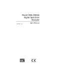
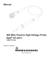
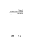
Model 2022
Spectroscopy
Amplifier
9231208C
User’s Manual
Copyright 2010, Canberra Industries, Inc. All rights reserved.
The material in this document, including all information, pictures,
graphics and text, is the property of Canberra Industries, Inc. and
is protected by U.S. copyright laws and international copyright
conventions.
Canberra expressly grants the purchaser of this product the right
to copy any material in this document for the purchaser’s own use,
including as part of a submission to regulatory or legal authorities
pursuant to the purchaser’s legitimate business needs.
No material in this document may be copied by any third party, or
used for any commercial purpose, or for any use other than that
granted to the purchaser, without the written permission of
Canberra Industries, Inc.
Canberra Industries, 800 Research Parkway, Meriden, CT 06450
Tel: 203-238-2351 FAX: 203-235-1347 http://www.canberra.com
Canberra is an AREVA company.
The information in this document describes the product as
accurately as possible, but is subject to change without notice.
Printed in the United States of America.
For technical assistance, call our Customer Service Hotline at
1-800-255-6370 or email [email protected].
Table of Contents
1. Introduction . . . . . . . . . . . . . . . . . . . . . . . . . . . . . 1
2. Controls and Connectors . . . . . . . . . . . . . . . . . . . . . . 2
Front Panel . . . . . . . . . . . . . . . . . . . . . . . . . . . . . . . . . . . . . . . . . . . . . 2
Rear Panel . . . . . . . . . . . . . . . . . . . . . . . . . . . . . . . . . . . . . . . . . . . . . . 3
Internal Controls. . . . . . . . . . . . . . . . . . . . . . . . . . . . . . . . . . . . . . . . . . . 4
3. Operations . . . . . . . . . . . . . . . . . . . . . . . . . . . . . . 5
Installation . . . . . . . . . . . . . . . . . . . . . . . . . . . . . . . . . . . . . . . . . . . . . . 5
Spectroscopy System Operation. . . . . . . . . . . . . . . . . . . . . . . . . . . . . . . . . . . 5
System Setup . . . . . . . . . . . . . . . . . . . . . . . . . . . . . . . . . . . . . . . . . . 6
Performance Adjustments . . . . . . . . . . . . . . . . . . . . . . . . . . . . . . . . . . . . 7
Resolution Versus Count Rate and Shaping . . . . . . . . . . . . . . . . . . . . . . . . . . 11
Resolution Destroying Interferences. . . . . . . . . . . . . . . . . . . . . . . . . . . . . . 11
A. Specifications . . . . . . . . . . . . . . . . . . . . . . . . . . . 13
Inputs . . . . . . . . . . . . . . . . . . . . . . . . . . . . . . . . . . . . . . . . . . . . . . . . 13
Outputs . . . . . . . . . . . . . . . . . . . . . . . . . . . . . . . . . . . . . . . . . . . . . . . 13
Front Panel Controls . . . . . . . . . . . . . . . . . . . . . . . . . . . . . . . . . . . . . . . . 13
Internal Controls . . . . . . . . . . . . . . . . . . . . . . . . . . . . . . . . . . . . . . . . . . 14
Performance . . . . . . . . . . . . . . . . . . . . . . . . . . . . . . . . . . . . . . . . . . . . 14
Connectors . . . . . . . . . . . . . . . . . . . . . . . . . . . . . . . . . . . . . . . . . . . . . 15
Power Requirements . . . . . . . . . . . . . . . . . . . . . . . . . . . . . . . . . . . . . . . . 15
Physical . . . . . . . . . . . . . . . . . . . . . . . . . . . . . . . . . . . . . . . . . . . . . . 15
Environmental . . . . . . . . . . . . . . . . . . . . . . . . . . . . . . . . . . . . . . . . . . . 16
B. Environmental Considerations . . . . . . . . . . . . . . . . . . 17
i
Important Safety Considerations
Read Carefully
Indicates warning of mains or high voltage present at output labeled HV.
Risk of electrical shock if covers are removed.
Caution - risk of danger. Refer to documentation for detailed explanation of caution
symbol wherever marked.
Product complies with appropriate current EU directives.
Example of "Cue" mark. Product complies with appropriate current
FCC (UL)/CSA 61010-1 directives.
Manufacturer’s Address
Canberra Industries, Inc.
800 Research Parkway
Meriden, CT 06450
ii
Model 2022 Spectroscopy Amplifier
1. Introduction
The Model 2022 Spectroscopy Amplifier provides excellent pulse symmetry, minimum sensitivity of output amplitude to variations in detector rise time, and maximum
signal to noise ratio. Unipolar shaping is achieved with one differentiator and two active filter integrators. The differentiator is placed early in the amplifier to insure good
overload recovery. The integrators are placed late to minimize noise contribution from
the gain stages. The amplifier offers six front panel selectable pulse shaping time constants: 0.5, 1, 2, 4, 8 and 12 μs.
The Model 2022 employs Canberra’s unique baseline restorer for optimum performance with high resolution detector systems. The gated baseline restorer automatically
adjusts the restoration rate and threshold optimizing performance to the incoming
count rate and system noise level.
Simultaneous unipolar and bipolar outputs are available at both front and rear panel
BNC connectors. The bipolar output can be used for counting, timing, or gating.
The Model 2022 borrows the Model 2020’s dc stability and low noise to provide a
high performance spectroscopy amplifier in a single width NIM module.
Figure 1 Position Sensitive Detector System
User’s Manual - ICN 9231208C
1
Chapter 2 - Controls and Connectors
2. Controls and Connectors
Front Panel
This is a brief description of the 2023’s front panel controls, indicators, and connectors. For more detailed information, refer to Appendix A, Specifications.
Figure 2 Front Panel Controls and Connectors
2
Model 2022 Spectroscopy Amplifier
Rear Panel
Rear Panel
This is a brief description of the 2022’s rear panel connectors. For more detailed information, refer to Appendix A, Specifications.
Figure 3 Rear Panel Connectors
User’s Manual - ICN 9231208C
3
Chapter 2 - Controls and Connectors
Internal Controls
For proper operation of the Model 2022, jumpers J1 and J2 must be placed in the OUT
position.
Figure 4 Internal Controls (Right Side Cover Removed)
4
Model 2022 Spectroscopy Amplifier
Installation
3. Operations
The purpose of this section is to familiarize the user with the operation of the Model
2022 Amplifier and to check that the unit is functioning correctly. If the following procedures are carried out, the user will gain sufficient familiarity with this instrument to
permit its proper use in the system at hand.
Installation
The Canberra Model 2000 bin and power supply, or other bin and power supply sys tems conforming to DOE/ER-0457T will accommodate the Model 2022. The right
side cover of the two-width NIM module acts as a guide for insertion of the instrument. The module is secured in place by turning the two front-panel captive screws
clockwise until finger tight. It is recommended that the NIM bin power switch be OFF
whenever the module is installed or removed.
The Model 2022 can be operated where the ambient air temperature is between 0 °C
and +50 °C (+120 °F maximum). Perforations in the top and bottom sides permit cooling air to circulate through the module. When relay rack mounted along with other
heat generating equipment, adequate clearance should be provided to allow sufficient
air flow through both the perforated top and bottom covers of the NIM bin.
Spectroscopy System Operation
A block diagram of a typical Canberra gamma spectroscopy system is shown in Figure
5.
Figure 5 Typical Gamma Spectroscopy System
User’s Manual - ICN 9231208C
5
Chapter 3 - Operations
System Setup
Internal Controls
1. Prior to installation, the internal controls should be set to their desired
positions. See Figure 4 for the locations of the controls.
There are two jumper plugs (J1 and J2) that set the UNIPOLAR output to the
prompt (OUT) mode, these jumper should be left in the OUT position.
There are two jumper plugs which select the output impedance of the front
panel (only) UNIPOLAR (J4) and BIPOLAR (J3) outputs. The output
impedances can be changed from 0 ohms to approximately 93 ohms. The
Model 2022 is shipped with the output impedance set for 0 ohms. The rear
panel outputs have a fixed impedance of 93 ohms, series connected.
When using the front panel low impedance output, short lengths of
interconnecting coaxial cable need not be terminated. To prevent possible
oscillations, longer cable lengths should be terminated at the receiving end in
a resistive load equal to the cable impedance (93 ohms for type RG-62
cable).
The 93 ohm output may be safely used with RG-62 cable up to a few
hundred meters. However, the 93 ohm impedance is in series with the load
impedance, and a decrease in the total signal range may occur. For example,
a 50% loss will result if the load impedance is 93 ohms.
Another jumper plug (J7) is provided to select a linear or an exponential
restorer response. The linear response is optimum for the faster shaping-time
constants and their associated noise spectra. The slower shaping-time
constants produce noise spectra having proportionately lower frequency
components, requiring a different restorer response. The exponential
response is better suited to these shapings.
The Model 2022 is shipped with the restorer response jumper plug in the
linear (L) response position, which will give the best restorer response for
shaping-time constants of 0.5, 1, 2, and 4 μs. These are the time constants
generally used with Ge, proportional counter, surface barrier, and
scintillation photomultiplier detectors.
The exponential (E) response position yields optimum restorer performance
with shaping-time constants of 8 and 12 μs. These time constants are most
often used with Planar Ge and Si(Li) detectors. The exponential response
may also be used with the other shaping time constants without loss of
resolution performance, provided that the input count-rate remains below 20
kcps.
6
Model 2022 Spectroscopy Amplifier
Spectroscopy System Operation
2. Insert the Model 2022 into a standard NIM bin. Preamp power is provided by
means of a connector located on the rear panel of the Model 2022 amplifier.
Allow the entire system to warm up and stabilize.
3. Set the Model 2022 controls as follows:
Shaping:
Coarse Gain:
Fine Gain:
2 μs
100
7.2
4. Set the INPUT POLARITY switch to match the output polarity of the
preamp (positive, +, for a Canberra Model 2001 Preamp). This will give
approximately a 9V output when using a preamp gain of 100 mV/MeV and a
60
Co source.
5. Install a “Tee” connector on the Model 2022 UNI POLAR output. Connect
one end to the ADC’s INPUT. The ADC must be direct coupled for linear
input signals to fully exploit the rate capabilities of the Model 2022. All
Canberra ADCs are dc coupled.
6. Connect the other end of the “Tee” connector to an oscilloscope to monitor
the UNIPOLAR output.
Performance Adjustments
The pole/zero trim, which is extremely critical for good high count-rate resolution performance, can be adjusted in either of two ways. The first used a detector and a standard source or radiation. The other used a square wave generator. Each of these is
described in the following paragraphs.
Pole/Zero Using a Ge Detector and 60Co
Adjust the source’s count to between 2 kcps and 25 kcps. While observing
UNIPOLAR output on the scope, adjust the pole/zero so that the trailing edge of the
unipolar pulse returns to the baseline with no over- or undershoots. Figure 6 shows the
correct setting of the P/Z control, with Figures 7 and 8 showing under- and overcompensation for the preamplifier decay time-constant. Notice some small amplitude
signals with long decay times in Figure 6. These are due to charge trapping in the detector and cannot be corrected by the P/Z control.
User’s Manual - ICN 9231208C
7
Chapter 3 - Operations
Figure 6 Correct Pole/Zero Compensation
Figure 7 Undercompensated Pole/Zero
Oscilloscope
Vert: 50 mV/div
Horiz: 10 μs/div
Source 60Co
1.33 MeV peak: 7 V amplifier
Count Rate: ≈ 2 kcps
Shaping: 2μs
Figure 8 Overcompensated
Pole/Zero
8
Model 2022 Spectroscopy Amplifier
Spectroscopy System Operation
Pole/Zero Adjustment Using a Square Wave and Preamp Test Input
1. Driving the preamp test input with a square will allow a more precise
adjustment of the amplifier P/Z.
2. The amplifier’s controls should basically be set for its intended application:
COARSE GAIN. SHAPING, INPUT POLARITY.
3. Adjust the square wave generator for a frequency of approximately 1 kHz.
4. Connect the square wave generator’s output to Preamp’s TEST INPUT.
5. Remove all radioactive sources from the vicinity of the detector
6. Set the scope’s channel 1 vertical sensitivity to 5 V/div and adjust the main
time base to 0.2 ms/div. Monitor the Model 2022 UNIPOLAR output and
adjust the square wave generator’s amplitude control (attenuator) for output
signals of ±8 V.
Note: Both positive and negative unipolar pulses will be observed at the output.
7. Reduce the scope vertical sensitivity to 50 mV/div. See the note below.
Note: At high count rates, the Pole/Zero adjustment is extremely critical for maintaining good resolution and low peak-shift. For a precise and optimum setting
for the Pole/Zero, a scope vertical sensitivity of 50 mV/div should be used.
Higher scope sensitivities can also be used. but result in a less precise
Pole/Zero adjustment. However, most scopes will over load for a 10 V input
signal when vertical sensitivity is set for 50 mV/div. Overloading the scope input will distort the signals’ recovery to the baseline. Thus the Pole/Zero will be
incorrectly adjusted, thereby resulting in a loss of resolution at high
count-rates. To prevent overloading the scope, a clamping circuit, such as Canberra Model LB1502 Schottky Clamp Box, should be used.
Figure 9 shows the correct setting of the Pole Zero control. Figures 10 and 11 show
under- and over-compensation for the preamplifier decay-time constant. As illustrated
in Figure 9, the UNIPOLAR output signal should have a clean return to the baseline
with no bumps, overshoots or undershoots.
Note: When adjusting the P/Z using the square wave technique, the calibration
square wave generated by the oscilloscope can be used. Most scopes generate a
1 kHz square wave used to calibrate vertical gain and probe compensation.
Connect the scope CALIBRATION Output through an attenuator to the
preamp input and repeat steps one through six in “Performance Adjustments”
on page 7.
User’s Manual - ICN 9231208C
9
Chapter 3 - Operations
Figure 9 Correct Pole/Zero Compensation
Figure 10 Undercompensated Pole/Zero
Figure 11 Overcompensated Pole/Zero
10
Model 2022 Spectroscopy Amplifier
Spectroscopy System Operation
Restorer Response
Faster shaping-time constants (0.5 through 4 μs) give rise to output noise spectra having different frequency components than the slower shaping-time constants (5 through
12 μs). The Model 2022 provides a restorer response for each of the two conditions:
linear (L) response for the faster time constants and an exponential (E) response for
the slower time constants. Jumper plug J7 (see figure 4) selects the required response.
Shipped in the linear (L) position. See “System Setup, Internal Controls” on page 6 for
more information.
MCA Controls
To obtain optimum resolution, the Lower Level Discriminator (LLD) on the
MCA/ADC should be set just above the noise so that the effects of pileup a minimized.
Resolution Versus Count Rate and Shaping
The 2 μs shaping-time constant is near-optimum for Ge detector systems over a wide
range of incoming count rates. For high resolution, larger shaping-time constants offer
a better signal-to-noise (S/N) ratio, resulting in better resolution. However, as the
count rate increases, the effects of pileup will degrade the resolution much sooner. The
optimum shaping-time constant depends on the detector characteristics (such as its
size, configuration, and collection characteristics), preamplifier, and incoming count
rate.
Below is a list of the optimum shaping-time constant ranges for other common detectors:
Scintillation Photomultiplier
Gas Proportional Counters .
Silicon Charged Particle . .
Coaxial Germanium . . . . .
Planar Germanium . . . . .
Cooled Silicon. . . . . . . .
.
.
.
.
.
.
.
.
.
.
.
.
.
.
.
.
.
.
.
.
.
.
.
.
.
.
.
.
.
.
0.5
0.5 through 2
0.5 through 2
2 through 4
4 through 12
8 through 12
Resolution Destroying Interferences
Vibration Transmitted to Detector and Cryostat
This can be through the floor or mounting, as well as direct audio coupling through the
air. Vibration isolators in the mounting and sound absorbing covers around the detector can reduce this problem.
Close Proximity of a Radio Station Picked Up by the Cryostat’s “Dipstick”
Good contact between the dipstick and the cryostat can often help solve this problem.
Beware of grounding the cryostat and dipstick because this may increase power line
frequency (50 or 60 Hz) ground loops.
User’s Manual - ICN 9231208C
11
Chapter 3 - Operations
Ground Loops and Power Line Frequency Interference Caused by Long
Cable Connections Between Detector, Preamplitier and Shaping Amplifier
There is no general solution for this problem. As a first step, the preamp should use the
power supplied by the main shaping amplifier. Second, the system should have a single point house ground. For example, on a general system connect the NIM bin to
house ground via the ac line cord. Isolate all other equipment requiring ac voltage
from the house ground. Connect all the chassis in the system to the grounded NIM bin
using heavy braided wire.
High Voltage Power Supplies (HVPS)
Generally, an ac line powered HVPS should float from power line ground with the
only ground being made at the preamplifier through the high voltage connecting cable.
Analyzer EMI
If the detector is located within three to five meters (10 to 15 feet) of a multichannel
analyzer containing ferrite CORE memory, it can receive EMI (electromagnetic interference). This is due to high memory-core-currents during the memory cycle of the analyzer. The only practical cure for this problem is to operate the analyzer in the “Live”
Mode of accumulation. That way, the memory cycle operates only while no signal is
being analyzed.
Amplifier Parasitic Oscillations
If the cable connecting the front panel outputs of the amplifier to the ADC exceed
three to six meters (10 to 15 feet) in length, oscillations can occur. The cure is to use
RG-62 cable (93 ohm impedance) and terminate the ADC end of the cable with a 93
ohm metal film resistor. Alternatively, the 93 ohm output impedance of the amplifier
can be used with no terminator.
Trouble Isolated to Ground Loops and or RF EMI
If trouble is isolated to ground loops and or RF EMI, detector-system loop-buster accessories are available to help minimize these effects. An application note entitled
“System Considerations with High Resolution Detectors” is available from the factory.
12
Model 2022 Spectroscopy Amplifier
Inputs
A. Specifications
Inputs
INPUT – Accepts positive or negative pulses from an associated preamplifier; amplitude: ±10 V divided by the selected gain for linear response; ±12 V maximum; rise
time: less than SHAPING time constant; decay time constant; 40 μs to ∞ for 0.5, 1, 2,
4 and 8 μs shaping time constants, 100 μs to ∞ for 12 μs shaping time constant; Zin ≈ 1
kΩ; front and rear panel BNC connectors.
Outputs
UNIPOLAR OUTPUT – Provides positive linear active-filtered near-Gaussian shaped
pulses; amplitude linear to +10 V, 12 V max.; dc restored; output dc level factory calibrated to 0±5 mV, front panel Zout <1 Ω or ≈ 93 Ω, internally selectable; rear panel Zout
≈ 93 Ω; short circuit protected; front and rear panel BNC connectors.
BIPOLAR OUTPUT – Provides prompt positive lobe leading linear active-filtered bipolar-shaped pulses; amplitude linear to +10 V, 12 V max., negative lobe is approximately 70% of positive lobe; dc coupled; output dc level ±25 mV; front panel Z out <1
Ω or ≈ 93 Ω, internally selectable; rear panel Zout ≈ 93 Ω; short circuit protected; front
and rear panel BNC connectors.
Front Panel Controls
COARSE GAIN – Rotary switch selects gain factors of X10, X30, X100, X300,
X1000 and X3000.
FINE GAIN – Ten-turn locking-dial precision potentiometer selects variable gain factor of X0.3 to X1.3; resetability ≤0.03%.
INPUT POLARITY – Toggle switch selects the polarity of the incoming preamplifier
signal.
P/Z – Multi-turn screwdriver adjustable pole/zero potentiometer optimizes amplifier
baseline recovery and overload performance for the preamplifier fall time constant and
the 2022’s pulse shaping chosen; 40 μs to ∞ for 0.5, 1, 2, 4 and 8 μs SHAPING time
constants, 100 μs to ∞ for 12 μs SHAPING time constant.
User’s Manual - ICN 9231208C
13
Appendix A - Specifications
SHAPING TIME – Rotary switch provides 0.5, 1, 2, 4, 8 and 12 μs basic shaping time
constants.
Internal Controls
UNIPOLAR Zout – Jumper plug provides Zout ≤1 Ω or ≈ 93 Ω for the front panel
UNIPOLAR output. Shipped in the ≤1 Ω position.
BIPOLAR Zout – Jumper plug provides Zout ≤1 Ω or ≈ 93 Ω for the front panel
BIPOLAR output. Shipped in the ≤1 Ω position.
L/E – Jumper plug selects a linear or exponential restorer response. Shipped in the L
(linear) position.
Performance
GAIN RANGE – Continuously variable from X3 to X3900, product of COARSE and
FINE GAIN controls.
GAIN DRIFT – ≤±0.0075%/°C.
DC LEVEL DRIFT – UNIPOLAR output: ≤±10 μV/°C; BIPOLAR OUTPUT: ≤±50
μV/°C.
INTEGRAL NON-LINEARITY – ≤±0.05%, over total output range for 2 μs shaping.
CROSSOVER WALK – BIPOLAR output: ≤±3 ns for 50:1 dynamic range and 2 μs
shaping when used with Canberra Model 2037A Edge/Crossover Timing Single Channel Analyzer.
OVERLOAD RECOVERY – UNIPOLAR (BIPOLAR) output recovery to within
±2% (1%) of full scale output from X1000 overload in 2.5 (2.0) non-overloaded pulse
widths, at full gain, any shaping time constant and pole/zero cancellation properly set.
NOISE CONTRIBUTION – ≤4.0 μV true RMS UNIPOLAR (7.1 μV BIPOLAR) output referred to input, 2 μs shaping and amplifier gain ≥100.
14
Model 2022 Spectroscopy Amplifier
Connectors
PULSE SHAPING – Near-Gaussian shape; one differentiator (two for bipolar), two
active filter integrators; UNIPOLAR time to peak: 2.35X shaping time; pulse width:
7.3X shaping time BIPOLAR time to crossover: 2.8X shaping time, time to peak,
pulse width and crossover times measured at 0.1% of full scale output; 1 μs SHAPING
center frequency: 150 kHz; band width: 180 kHz; f c and BW for other shaping are
multiples of that given for 1 μs.
RESTORER – Active gated.
SPECTRUM BROADENING – The FWHM of a 60Co 1.33 MeV gamma peak for an
incoming rate of 2 kcps to 100 kcps and a 9 V pulse height will typically change <14%
for 2 μs shaping. These results may not be reproducible if associated detector exhibits
an inordinate amount of long rise time signals.
COUNT RATE STABILITY – The peak position of a 60Co 1.33 MeV gamma peak for
an incoming count rate of 2 kcps to 100 kcps and a 9 V pulse height will typically shift
<0.024% for 2 μs shaping.
Connectors
All signal connectors are BNC type.
PREAMP POWER – Rear panel, Amphenol type 17-10070.
Power Requirements
+24 V dc – 125 mA +12 V dc – 75 mA
–24 V dc – 150 mA –12 V dc – 65 mA
Physical
SIZE – Standard single-width NIM module 3.43 x 22.12 cm (1.35 x 8.71 in.) per
DOE/ER-0457T.
NET WEIGHT – 0.9 kg (2.0 lb).
SHIPPING WEIGHT – 1.9 kg (4.1 lb).
User’s Manual - ICN 9231208C
15
Appendix A - Specifications
Environmental
OPERATING TEMPERATURE RANGE - 0 to 50 °C (32 to 122 °F).
OPERATING HUMIDITY – 0 to 80% relative, non-condensing.
Meets the environmental conditions specified by EN 61010, Installation Category I,
Pollution Degree 2.
16
Model 2022 Spectroscopy Amplifier
B. Environmental Considerations
This unit complies with all applicable European Union requirements.
Compliance testing was performed with application configurations commonly used for
this module; i.e. a CE compliant NIM Bin and Power Supply with additional CE compliant application-specific NIM were racked in a floor cabinet to support the module
under test.
During the design and assembly of the module, reasonable precautions were taken by
the manufacturer to minimize the effects of RFI and EMC on the system. However,
care should be taken to maintain full compliance. These considerations include:
• A rack or tabletop enclosure fully closed on all sides with rear door access
• Single point external cable access
• Blank panels to cover open front panel Bin area
• Compliant grounding and safety precautions for any internal power distribution
• The use of CE compliant accessories such as fans, UPS, etc.
Preventive Maintenance
This unit does not require any periodic cleaning maintenance.
Any maintenance should be performed by a qualified Canberra service representative.
Operating Protection Impairment
Canberra is not liable for any operational malfunctions or personal injuries due to mishandling or unauthorized repair and maintenance not detailed in this manual.
Cleaning/Decontamination
When needed, the unit may be cleaned. Remove power from the unit before cleaning.
Use only a soft cloth dampened with warm water and do not allow water to enter the
unit. Make sure unit is fully dry before restoring power. Because of excess holes in the
NIM wrap, do not use any liquids to clean the wrap, side, or rear panels.
User’s Manual - ICN 9231208C
17
Notes
18
Request for Circuit Information
The Schematics, Block Diagrams and/or Circuit Description may be available for this
unit directly from CANBERRA. Request can be made by calling, faxing, or emailing:
Training and Technical Services Department
Canberra Industries
800 Research Parkway, Meriden, CT 06450
Telephone: (800) 255-6370
FAX: (203) 639-2067
Email: [email protected]
If you would like schematics and/or a circuit description, if available, for this unit,
please provide us with the following information.
Your Name
_______________________________________
Your Address
_______________________________________
_______________________________________
_______________________________________
_______________________________________
_______________________________________
Unit’s model number
_________________________
Unit’s serial number
_________________________
Note: Schematics, block diagrams, and circuit descriptions are provided for information only; if you service or repair or try to service or repair this unit without
Canberra’s written permission you may void your warranty.
Notes
Warranty
Canberra (we, us, our) warrants to the customer (you, your) that for a period of ninety (90) days from the date of
shipment, software provided by us in connection with equipment manufactured by us shall operate in accordance
with applicable specifications when used with equipment manufactured by us and that the media on which the
software is provided shall be free from defects. We also warrant that (A) equipment manufactured by us shall be
free from defects in materials and workmanship for a period of one (1) year from the date of shipment of such
equipment, and (B) services performed by us in connection with such equipment, such as site supervision and
installation services relating to the equipment, shall be free from defects for a period of one (1) year from the date of
performance of such services.
If defects in materials or workmanship are discovered within the applicable warranty period as set forth above, we
shall, at our option and cost, (A) in the case of defective software or equipment, either repair or replace the
software or equipment, or (B) in the case of defective services, reperform such services.
LIMITATIONS
EXCEPT AS SET FORTH HEREIN, NO OTHER WARRANTIES OR REMEDIES, WHETHER STATUTORY,
WRITTEN, ORAL, EXPRESSED, IMPLIED (INCLUDING WITHOUT LIMITATION, THE WARRANTIES OF
MERCHANTABILITY OR FITNESS FOR A PARTICULAR PURPOSE) OR OTHERWISE, SHALL APPLY. IN NO
EVENT SHALL CANBERRA HAVE ANY LIABILITY FOR ANY SPECIAL, EXEMPLARY, PUNITIVE, INDIRECT
OR CONSEQUENTIAL LOSSES OR DAMAGES OF ANY NATURE WHATSOEVER, WHETHER AS A RESULT
OF BREACH OF CONTRACT, TORT LIABILITY (INCLUDING NEGLIGENCE), STRICT LIABILITY OR
OTHERWISE. REPAIR OR REPLACEMENT OF THE SOFTWARE OR EQUIPMENT DURING THE
APPLICABLE WARRANTY PERIOD AT CANBERRA'S COST, OR, IN THE CASE OF DEFECTIVE SERVICES,
REPERFORMANCE AT CANBERRA'S COST, IS YOUR SOLE AND EXCLUSIVE REMEDY UNDER THIS
WARRANTY.
EXCLUSIONS
Our warranty does not cover damage to equipment which has been altered or modified without our written
permission or damage which has been caused by abuse, misuse, accident, neglect or unusual physical or
electrical stress, as determined by our Service Personnel.
We are under no obligation to provide warranty service if adjustment or repair is required because of damage
caused by other than ordinary use or if the equipment is serviced or repaired, or if an attempt is made to service or
repair the equipment, by other than our Service Personnel without our prior approval.
Our warranty does not cover detector damage due to neutrons or heavy charged particles. Failure of beryllium,
carbon composite, or polymer windows, or of windowless detectors caused by physical or chemical damage from
the environment is not covered by warranty.
We are not responsible for damage sustained in transit. You should examine shipments upon receipt for evidence
of damage caused in transit. If damage is found, notify us and the carrier immediately. Keep all packages,
materials and documents, including the freight bill, invoice and packing list.
Software License
When purchasing our software, you have purchased a license to use the software, not the software itself. Because
title to the software remains with us, you may not sell, distribute or otherwise transfer the software. This license
allows you to use the software on only one computer at a time. You must get our written permission for any
exception to this limited license.
BACKUP COPIES
Our software is protected by United States Copyright Law and by International Copyright Treaties. You have our
express permission to make one archival copy of the software for backup protection. You may not copy our
software or any part of it for any other purpose.
Revised 1 Apr 03